publication MiG-19 Day Interceptor & Two-seat variants MiG-19, S, SV, S-105, Shenyang J-6/F-6, JZ-6, JJ-6/FT-6 J-6I, II & III [ MiG-19 Day Interceptor...
166 downloads
136 Views
40MB Size
publication
MiG-19 Day Interceptor & Two-seat variants MiG-19, S, SV, S-105, Shenyang J-6/F-6, JZ-6, JJ-6/FT-6 J-6I, II & III
ACKNOWLEDGEMENTS The publishers gratefully acknowledge the co-operation of: Eddy de Kruijff, Josef Faul and Zdenek Prochazka A sincere word of thanks is also extended to: Jozef Andal, Miroslav Balous, Miroslav Bily, Radko Bohdalek, Stephan Boshniakov, Thomas Bufimann, Piotr Butowski, Jaroslav Farkas,Yefim Gordon, Martin Janousek, Michael Janousek, Miroslav Khol, Jr., Bohumir Kudlicka, David Nicolle, Jaroslav Matoulek, Ivo Pavlovsky, Sergei Popsuyevich, Stanislav Skala, Vaclav Sorel, Petr Soukop, Hans-Heiri Stapfer, Eduard Stehlik, Stanislav Stepanek +, Andy Sun, Pavel Tyc, Jiri Vlach, Mirostaw Wasielewski, Leon Wong, Andrei Zinchuk. A special thanks is also expressed to: Air Commodore Shahid Nisar Khan, Samungli Base Commander, and Wing Commander A. Nawaz Khan, Pakistan Air Force HQ.
SOURCES
[
MiG-19 Day Interceptor & Two-seat varian MiC-19, S,SV, S-105, Shenyang J-6/F-6, JZ-6, JJ-S/FT-6 J-6I. II & III
Yefim Gordon collection, Prague-Kbely Aviation Museum, China Aviation Museum Changping (Beijing), Samungli AB, Flugplatzmuseum Cottbus archive, Aviation Museum at Khodynka airfield (Moscow), MARK I archive
Front cover photo:
COPYRIGHT © 2003 by 4+ Publishing Co.
An unidentified Czechoslovak S-105 (MiG-19S) Farmer C, of the Sth Fighter Regiment, lands at its home base at Line, southwest of Pilsen. Red formation keeping/aligning stripes painted on the wing fences and below the cockpit canopy, and the lack of wing-mounted cannons suggest it was taking part in one of the military air parades organized in the mid-sixties.
All rights reserved. No part of this publication may be reproduced nor copied in any form electronic, electrical, chemical, mechanical, optical, photocopying or otherwise, without prior written permission of the publishers. It is forbidden to use any part of this publication on websites.
Photo Zdenek Prochazka collection via Petr Soukop
Rear cover photo: An unusually Yellow-coded MiG-19S Farmer C converted into a weapons test-bed for the K-13 (AA-2 Atoll) airto-air missile. Designated the SM-9/3T, it was thoroughly tested and flown between 11 February and 3 March 1959. Photo Yefim Gordon collection
THE AUTHORS' WORD Dear reader, Thank you for your buying another publication with the 4+ trademark. This publication is devoted to the first Soviet production fighter capable of attaining supersonic speed in level flight. It quickly became the true Cold War warrior, equipping a number of the air forces of former Warsaw Pact countries. It was also licence-built in Czechoslovakia and China, with the latter's product still flying at the turn of this century. The first volume, now in your hands, deals with the day fighter models only while the second, due to be published soon, will describe the radar-equipped versions. We hope this publication will satisfy your interest in this type of aeroplane.
4+ publications already published: 4+001 MiG-21 Fishbed (out of print) 4+002 Su-22 Fitter (out of print) 4+003 Mi-24 Hind (out of print) 4+004 MiG-23 Flogger Fighter variants (out of print) 4+005 MiG-29 Fulcrum 4+006 Su-25 Frogfoot (out of print) 4+007 MiG-15 Fagot 4+008 Westland Wessex (out of print) 4+009 Westland Lysander 4+010 Hawker Tempest 4+011 Hawker Sea Hawk 4+012 Miles Magister 4+013 Fairey Fulmar 4+014 Westland Whirlwind Fighter/Fighter-Bomber 4+015 Vickers-Armstrongs Wellington Medium Bomber variants 4+016 Westland Wyvern
MiG-19 Farmer Day Interceptor & Two-seat variants publication, 4+017 Authors of the text - the history and summary, technical description, armament and equipment, colours and markings - Ivo Pavlovsky, Michal Ovcacik, Karel Susa Photo captions - Michal Ovcacik, Karel Susa Photos (unless otherwise stated) - Michal Ovcacik, Karel Susa, MARK I archive Plans and drawings - Michal Ovcacik, Karel Susa, MARK I archive Camouflage drawings - © MARK I Litho - Art-D, Graficky atelier Cerny Ltd., Prague 10, Czech Republic Printed by TRICO Ltd., Prague 7, Czech Republic 4+ is a ® registered trademark
If not available in your area and/or for more information on 4+ publications, write to:
MARK I Ltd. POBoxlO 100 31 Prague 10 - Strasnice CZECH REPUBLIC You can also e-mail us at:
marki (fficmail.cz Published by 4+ Publishing Co., PO Box 10, 100 31 Prague 10 - Strasnice, Czech Republic © 4+ v.o.s., 1st edition, Prague 2003 ISBN 80-900708-8-4
A nice shot of the Czechoslovak-built S-105 Farmer C, seen on 15 October 1963 at Brno-Turany AB. The aeroplane is from the fifth production batch and sports a large fin fillet. Note the ground crew member (seen lying behind the port underwing tank) closing the parachute bay doors.
MiG-19 Day Interceptor & Two-seat variants, the history and summary In July 1950 the Supreme Council in Moscow conceived the requirements for a new fighter whose performance would substantially surpass those of the MiG-15 Fagot and MiG-17 Fresco fighters. One of the design offices charged to develop such an aeroplane was the famous Mikoyan Gurevich Design Bureau, headed by Artyom I. Mikoyan. The result of the development, which in general followed the lines of its predecessors, appeared as the MiG-19. The aircraft started to leave the production lines of the State Aircraft Factory at Gorkiy (GAZ No.21) in 1954 under the factory in-house designation "product 59" and a year later production was also launched at Novosibirsk (GAZ No.153, as product 25). In March 1955, the first unit of the WS (Soviet Air Force) at Kubinka AB received their MiG-19s and on 3 July, a formation of 48 aeroplanes made a spectacular fly-past over Tushino, enabling Western intelligence to spot the modern fighter for the first time. Soon afterwards the MiG-19 received the NATO code name Farmer A. The MiG-19 was the first Soviet combat aircraft capable of reaching and maintaining supersonic speed in level flight. The definitive clear weather variant, the MiG-19S, meant a true leap forward in comparison to any other jet fighter of the time. In combat the MiG-19S proved to be an excellent dog fighter, with exceptional manoeuvrability, high thrust-to-weight ratio, plus very good handling capabilities and speed. Production of the MiG-19 in the Soviet Union was rather short-lived and had ceased by the late 1950s in favour of the more advanced MiG-21 Fishbed. Although not well received by Russian pilots and groundcrew, a new lease of life began in China, where a remarkable quantity would be built during the following decades. Later, during its operational career and despite lacking the sophistication of more modern fighters, the day fighter variant of the MiG-19 appeared to be a forceful warplane.Yet today, almost 50 years after the first airframe left the production line, the Chinese models remain in operational service in China, Albania and Bangladesh.
Development and Soviet production 1-340 (SM-1) was the first MiG-19 predecessor built in 1951 on the basis of the MiG-17F, with two Mikulin AM-5 axial-flow turbojets mounted side-by-side in a new rear fuselage. 1-360 (SM-2/1, SM-2/2) followed in 1952 as a new mid-wing escort fighter design. The fuselage, mounting two AM-5A engines, was extended by 1.6 m (5'3") while new wings, with a high-speed airfoil section, anhedral and boundary layer fences were optimised for supersonic flight. The 1-360 had a swept-back fin and T-shaped tail. A more spacious cockpit, with a reinforced bubble canopy, was fitted with an ejection seat and face shield ejection actuator. The armament was changed from the MiG-17-style cannon pack to two separate 37mm N-37D guns in the wing roots. Two aeroplanes were built and used for flight tests in the Zhukovskiy-based Flight Research Institute while the third airframe was used for static tests. The SM-2/1 did not break the sound barrier in level flight and reached a speed of M= 1.19 only in shallow dive. The SM-2/2 differed in having larger air brakes and enlarged cannon muzzle brakes. MiG-19 (SM-9/1, SM-9/2, products 59 and 25) was a new design with modified engines. The Mikulin OKB fitted their AM-9F turbojet (later re-designated the AM-9B) with an afterburner proportionally identical to the AM-5 unit. Its dry thrust was 25.5 kN (5,730 lb st) rising to 31.87 kN (7,165 lb st) in full afterburner. The main difference, compared to the SM-2, was an enlarged and reshaped fin and widened rear fuselage. The wings, with deep-chord fences, and fixed tailplanes were identical. The first flight of the SM-9/1 took place on 5 January 1954, closely followed by the second prototype. The SM-9/2 introduced a slab tailplane, mounted higher up on the fuselage, and featured a longer fuselage nose section, with reduced air intake diameter, larger nose wheel, ventral air brake, wing interceptors, cooling air scoops on the rear fuselage and a smaller rudder. No Pitot tubes were fitted and no armament was installed in the wing, although later three NR-23 cannons were added. During test flights the aircraft performed well, but it was sensitive to stick inputs during low speed pitch. The problem was resolved with an ARU-2A automatic flight control unit controlling the stick forces and stabilator deflection according to speed and altitude. Well before the end of acceptance trials, on 17 February 1954, the Council of Ministers ordered mass production of the MiG-19.The production aircraft differed from the SM-9/1 in armament, which comprised three 23mm NR-23 cannons instead of the former installation of one N-37D and two NR-23 guns. The MiG-19s were also fitted with two underwing pylons for bombs or drop tanks, and a pair of removable pylons for unguided rockets aft of the
main undercarriage wells. Other visible differences included a lack of gun muzzle blast shields, absence of Pitot tubes on the wing tips and a canopy without supporting frames. The MiG-19s possessed several drawbacks, especially a tendency to blow up in mid-air, causing a fair degree of unpopularity amongst pilots. The MiG OKB identified the problem as insufficient heat insulation of the rear fuselage fuel cells leading to overheating and ensuing fuel explosion. Other improvements comprised redesigned air brakes, which produced turbulence around the tailplane, and reshaping of the tail fairing behind the jet nozzles. The MiG-19 Farmer A entered service in large numbers during 1956, pending the introduction of the definitive slab-tailed MiG-19S model. MiG-19S (SM-9/3, products 61 and 26). The prototype first flew on 27 November 1955 piloted by K. Kokkinaki. It had a short nose, with large intake similar to that on the SM-9/1, an all-movable tailplane, shorter rudder with trim tab, shallow fuselage spine and a long fin fillet. Three NR-30 cannons were installed, with two guns in the wing roots and the third on the starboard side of the nose. The fuselage skin around the cannon muzzles was protected by blast guards. Although both the SM-9/2 and SM-9/3 were lost during tests, the latter demonstrated an excellent performance reaching the speed of M=1.46. The SM-9/3 was in fact a pattern for MiG-19S production superseding the original"sans suffix" version. The armament of most MiG-19S fighters comprised NR-30 cannons with muzzle brakes, although early production machines had unbraked NR-23 guns with small blast shields. Additionally, modifications to the RD-9B engines, wheel brakes, braking chute and control system were incorporated. Unlike the MiG-19, the 'S' variant was equipped with a third ventral air brake and spoilers below the wings; early MiG-19S's also had a short dorsal fin fillet. The KK-2 ejection seat was completed with a face curtain incorporated into the headrest. During serial production the two pylons for ORO-57K pods were repositioned to the wing leading edge. On some aircraft the short fin leading edge fillet received a small blister over an improved ARU-3V automatic flight control unit, which was enclosed by a longer fin fillet on later machines. The MiG-19S Farmer C was the most numerous version of the family, becoming the mainstay of Soviet fighter aviation of the fifties. MiG-19 (SM-2A) was modified in 1955 to carry four RO-70-5 pods each with five 70mm (2.75") ARS-70 unguided rockets. The aeroplane could carry either four pods or a combination of two pods and drop tanks. The trials proved satisfactory. MiG-19 (SM-2B, SM-2V, SM-21). The SM-2B was a MiG-19 modification fitted with ORO-190K launchers for two or four TRS-190 unguided rockets. The aircraft was later modified to carry two ARS-212M (S-21) rockets in APU-5 launchers. Re-designated the SM-2V it successfully passed state acceptance trials in 1957. The APU-5 launchers were also experimentally installed outboard the fuel tank hardpoints and as such the aeroplane was known as the SM-21. MiG-19 (SM-2G). A single aircraft was used in 1955-56 for flight tests with coupled launch tubes for ARS-160 unguided rockets. MiG-19 (SM-2D) was the modification, made in 1957, of the SM-2A enabling carriage of four 408/3 three-tube rocket pods for nine 85mm (3.34") TRS-85 FFARs. MiG-19 (SM-2M) was a MiG-19S fitted with two APU-5M missile rails on Type 369-Sh pylons for test launches of K-5M (RS-2US) radar-guided missiles. Such an arrangement was later utilised on the MiG-19P Farmer B interceptors. MiG-19 (SM-21), with the wing cannons retained, was modified as a weapons test-bed for the K-6 (AA-1 Alkali) radar-guided missiles. Live missile tests were conducted during May - December 1956. MiG-19S (SM-9/3T). In February 1959 a MiG-19S was upgraded with outboard wing pylons and APU-26 rails for K-13 IR AAMs. Firing data recorders were installed in place of the wing cannons. The programme was carried out successfully, with the missiles having no adverse effect on handling. MiG-19S (SM-9/9) was a special variant tested in 1959. A BDZ-55T weapons pylon for carrying a 244-N nuclear bomb was installed under the starboard wing near its root. Both the starboard wing and nose cannons were removed and an aerodynamic fairing was added to the wing/fuselage joint and around the pylon itself. Dummy bombs were successfully dropped both from level flight and during the toss-bombing manoeuvres. MiG-19SF (the 'F' denoting high-performance). A certain number of MiG-19S fighters were stripped of redundant on-board equipment to reduce weight and had the improved RD-9BF-1 or RD-9BF-2 engines fitted. These aircraft were later upgraded with outboard wing pylons for two R-3S (AA-2a Atoll) IR-guided AAMs. MiG-19SV (SM-9V) was a high-altitude interceptor developed to counteract highflying spy planes and reconnaissance balloons intruding on Soviet territory. The MiG OKB decided to improve the climb and service ceiling of the basic MiG-19 by the
installation of an upgraded RD-9BF engine (with raised turbine inlet temperature to 730° C), removing the wing cannons, dismantling the armour plating and increasing the wing area by 2 m2 (21.5 sq ft). A 12° flap setting for use at heights above 15,000 m (49,212 ft) was proposed to improve the wing lift and manoeuvring at speeds below Mach 0.9. At first two MiG-19s were modified as prototypes in 1956, soon followed by similar conversion of another two MiG-19S. To save weight the RV-2 altimeter and brake chute were also removed and KT-61 wheels with disc brakes were fitted to shorten landing runs. High-altitude missions also required more complex life support equipment in the form of a KKO-1 oxygen dispenser and a VSS-04A pressure suit. However, the suit proved to be cumbersome and poorly ventilated and therefore a new VKK-2 suit was introduced, soon supplemented by a GSh pressurised helmet. This combination allowed pilots to attain safe operational altitudes of 24,000 m (78,740 ft). Production MiG-19SV fighters did not have the larger-area wings and had its flaps setting reduced to 8°. RD-9BF-1 engines were fitted to several 'SV aircraft whereas some other received an improved RD-9BF-2s, with thrust increased to 32.36 kN (7,277 lb st) in full afterburner. A record altitude of 20,740 m (68,044 ft) was set on 6 December 1956 by the Nil WS pilot N. Korovushkin flying an SM-9V prototype, while a maximum speed of 1,572 km h V 977 mph (or Mach 1.48) at 10,000 m (32,810 ft) was also reached during another flight. The MiG-19SVs were produced anew at the GAZ No.21 factory, with an unknown number of MiG-19S fighters also converted to the 'SV standard. MiG-19R (SM-9R, the 'R' for reconnaissance) was a modification of the MiG-19SV. A special mount with AFA-39 cameras was installed in the compartment substituting the nose-mounted cannon. The aeroplane was successfully tested at Nil WS and reportedly produced only in limited numbers by the GAZ No.21 factory. MiG-19M (M-19) was a supersonic remote-controlled target drone based on both the MiG-19 and MiG-19S fighters, which had been retired from the front-line service. The modification comprised the removal of all superfluous equipment and installation of radio guidance system antennae on the nose, fin top and below the wings. MiG-19SU (SM-50, the 'IT standing for booster) was a high-altitude interceptor fitted with upgraded RD-9BM engines, delivering 31.58 kN (7,100 lb st), and a U-19 liquid fuel booster, with an SZ-20M rocket motor in a jettisonable underbelly fairing. Although the SM-50 did not pass the state acceptance trials, a small batch of five aircraft was produced in 1957 for training purposes including the GCI and high-altitude intercept methods. MiG-19S (SM-K/1, SM-K/2). Two series-built fighters were converted by the OKB-155 in 1957 to serve as test-beds for the guidance system of the K-10S (AS-2 Kipper) cruise missile. The YeS guidance system was fitted and subordinated to the YeN target illumination radar of the Tu-16K-10 missile carrier. YeS units and data recorder were installed in the fuselage, wing roots and in special underwing pods. MiG-19S (SM-9K, SM-30/1, SM-30/2, SM-30M, also designated the MiG-19P). In 1956 two fighters were converted for zero-length launches (ZELL) from a trailer, a system to be used to defend remote areas of the Soviet Union. Structural modifications were incorporated to the SM-30/1, and PRD-22R solid-fuel boosters were utilised. The second prototype had a further reinforced fuselage to withstand the high G-forces in force during take-off. In July 1957 the state acceptance trials began at the Nil WS and continued until November that year. Reportedly five aircraft and six launchers were produced, but due to the complex system and problems in finding suitable landing strips in remote areas, the SM-30 programme was shelved. Within the SM-30 project an unusual MiG-19SV, fitted with an arrester hook, was used for short landing trials. MiG-19 (SM-9D, SM-10/1, SM-10/2). To extend the operational range of the MiG-19, in-flight refuelling was considered, with three aircraft converted in 1954 and 1955 by adding refuelling receptacles to the port wing tip. Flight tests using the Tu-16 as a tanker were conducted in March 1957, but the modification was not accepted. MiG-19 (SM-20/1, SM-20/2 also known as the SM-20 and SM-20P). In 1956 two aircraft were used as test-beds for the Kh-20 (AS-3 Kangaroo) missile guidance system as part of Tu-95K-20 weapons system development. The SM-20/1 acted as a remote-controlled simulator while the SM-20/2 could be controlled either by the pilot or autopilot. After the completion of more than 150 test flights, the Kh-20 guidance system was accepted. Other various flying laboratories and test-beds were based on the MiG-19, but it is out of the scope of this publication to deal with all these minor alternative models. The MiG-19S Farmer Cs were supplied by the USSR only to three WarPac countries, Bulgaria (24 a/c), East Germany (12) and Czechoslovakia (13). Outside Europe the Soviet Union delivered a number MiG-19S to Afghanistan (18 a/c), the League of Arab Nations (at least 80 a/c to Egypt and 40 to Syria), Indonesia (at least 35), Iraq (15), North Korea (15) and North Vietnam (around 40) while other air forces around the world were supplied by the Chinese.
Czechoslovak production and service In 1953 the Czechoslovak Air Force was in need of supersonic fighters capable of intercepting high-flying intruders. The MiG-19S was chosen as the most suitable aeroplane and an agreement on delivery of Farmers from the USSR and on licenced production was signed in July 1956. The first "pattern" aeroplane was delivered in May 1957, followed by 13 aircraft, in the form of CKD kits. Another batch of 12 MiG-19S's arrived in crates at the end of 1957.The first aircraft, the '1006', flew on 6 February 1958. Due to discrepancies between the documentation and pattern aircraft, licenced production was temporarily halted, but was resumed in 1959, when the first series of 6 aircraft, designated the S-105 ('S' standing for fighter), was completed. A total of 104 MiG-19S,
in 5 production batches, had been built at the Aero Vodochody plant by November 1961; all of them were destined for the Czechoslovak AF. The engines, known as the M-09, were locally manufactured by Zavody J. Svermy, while overhauls were later carried out by Aero and the Aircraft Repair Works at Prague-Kbely. The MiG-19S fighters subsequently equipped eight fighter regiments, with the first aeroplanes going to the 1st FR (1. sip) at Ceske Budejovice and the 1 lth FR at Zatec.The last Farmer C was removed from service in June 1972. MiG-19SF (the 'F' denoting the photo reconnaissance, or MiG-19R). A single MiG19S (c/n 850012) was modified for reconnaissance by the removal of the fuselage cannon, No.2 fuel tank and other equipment. Two camera bays were provided, enabling three different installations for vertical and oblique photography: either 3x AFP-21KT or AFPN-21B cameras, or 2x ShFP-21B, one AFP-12.5 and one AK-16 (or AFP-12.5), or two AFPN-21B units. The aircraft was tested beginning from May 1959, but the project was cancelled in 1960.
Chinese production and export The MiG-19 licence programme in China was assigned to the Shenyang Aircraft Factory, by an agreement signed early in 1958. Initially MiG-19P Farmer Bs were to be manufactured under the designation J-6, but following unacceptable results, in terms of quality, production was halted and revived only in 1961 using original Soviet documentation and tooling. The day fighter model was now used as the basis, without any designation change. Shenyang J-6 was based on the MiG-19SF, with deliveries beginning in December 1961. During production the aircraft were upgraded with the installation of a braking parachute in a bullet-shape fairing at the base of the fin, thus becoming the J-6C. The export aeroplanes, designated the F-6C, were fitted with a Martin-Baker ejection seat and Westernised avionics (aircraft for Pakistan and Egypt). Shenyang J-6I was a high-altitude, day interceptor employing more powerful WP-6A turbojets of 29.42 kN (6,610 lb) dry thrust and 36.77 kN (8,270 lb) in full afterburner, and featuring a larger wing. All surplus on-board equipment was removed, including the two wing cannons. The nose section was fitted with a sharp-tipped, fixed nose cone on a splitter plate. Shenyang J-6II was an improved variant of the J-6I, with a 30mm cannon on the starboard side and 23mm gun on port. It featured a MiG-19S-style nose mounted Pitot tube and ventral placed braking parachute. Shenyang J-6III was based on the J-6II, with upgraded gun armament of three 30mm Type 30-1 cannons and relocated brake chute to the base of the rudder. Two upgraded Wopen WP-6A turbojets were mounted. Shenyang JJ-6 was a locally designed two-seat trainer, first flown in November 1970. Its forward-lengthened fuselage (by 0.33 m/l'l") accommodated a second (rear) seat for the instructor, with the cockpit covered by a widened windshield and two separate canopies, hinged to the starboard. The armament consisted of a single 30mm cannon. The aircraft differed from the J-6C in having its internal fuel capacity reduced to 2,000 litres (440 gal). Production amounted to 634 aircraft, with some machines exported under the designation FT-6. Shenyang JZ-6 was a reconnaissance modification, incorporating a camera compartment in the fuselage aft of the nose wheel bay. First flown on 2 July 1971, the JZ-6 has been the only dedicated reconnaissance aircraft in the PLAAF's inventory (until the arrival of the JZ-8), with around 100 aeroplanes still in service. The Chinese Farmer Cs and their optional models were produced by three state factories at Shenyang, Nanchang and Tianjin (Tientsin), reaching more than 4,500 examples; the majority of them were built as the J-6/F-6 (3,300 a/c) and JJ-6/FT-6 (637 a/c). Although Pakistan has never produced any F-6 fighters, it can be regarded as the biggest foreign user of the Chinese derivatives. Early-model aircraft supplied to the PAF were locally retrofitted with a chute container and additional outboard wing pylons for AIM-9B/J/P AAMs. Most late F-6s were upgraded through the installation of MB Mk.10 PKD ejection seats and the Rockwell Collins navigation system. A provision was made to carry a locally-designed 1,140 1 (251gal) underbelly semi-conformal fuel tank. The Pakistani aeroplanes were also modified to carry French FFARs instead of the Chinese rocket pods. Aircraft overhauls were carried out in the Aeronautical Complex at Kamra, while engine maintenance took place at the PAF Air Logistics Depot at Sharea Faisal. Pakistan took delivery of a total of 253 Shenyang-built Farmers, with a certain number of aircraft purchased from other countries. The original Chinese supply consisted of 4 batches: 74 F-6s (during 1965-66), 2x 60 F-6Cs (in 1972 and 1977) and an unknown quantity of FT-6s in 1980. Other operators of the Shenyang J-6 clear-weather fighter variants were Albania, Bangladesh, Congo, Egypt, Indonesia, Iran, Iraq, Cambodia (Kampuchea), North Korea, North Vietnam, Somalia, Sudan, Syria, Tanzania, Yemen and Zambia. • MiG-19 and MiG-19S production in the Soviet Union Designation MiG-19 MiG-19S, SV* MiG-19 MiG-19S, SV * SUBTOTAL TOTAL
Factory
1957 f959 7956 1958 1 118 1 59 No. 153 Novosibirsk 143 145 283 175 20 139 285 20 465 175 * MiG-19S and SV had the same product number 1,084 " all export MiG-19S a/c manufactured by GAZ No.21 No.21 Gorkiy "
1955 139
Pilots of the last two Pakistani F-6C squadrons, No. 17 "Tigers' and No.23 'Talons'proudly pose in front of their well maintained aeroplanes at SamungliAB. The recognisable identities of the aircraft are (right to left): 7839, 7635,8923, 7722 and 8913.
List of abbreviations AAM CKD kit FFAR GCI GvIAP HSI IFF ILS Nil WS
Air-to-air missile C o m p o n e n t Knocked-Down kit Folding-fin aircraft rocket G r o u n d - C o n t r o l l e d Intercept G u a r d s Fighter R e g i m e n t Horizontal Situation Indicator Identification F r i e n d or Foe Instrument Landing System Scientific Research Institute of theWS
OKB PLAAF
Experimental Design Bureau People's Liberation Army Air Force (Chinese Air Force) PTB jettisonable fuel tank PVO Anti-aircraft defence RHAWS Radar Homing And Warning System SHORAN Short Range Navigation (system) TACAN Tactical Air Navigation
WS
Army Air Forces of the USSR
Technical description of MiG-19S Farmer C The MiG-19S was a single-seat, supersonic twin-jet fighter designed for interception, close air support and limited fighter-bomber roles. It was a mid-wing, all-metal monoplane, with a back swept wing and all-movable horizontal tailplanes. The fuselage is of a stressed-skin aluminium construction, with the cross section being circular over the nose and gradually changing to oval over the engines. The fuselage, with a max. diameter of 1.45 m (4'9"), is divided into two main portions comprising 35 bulkheads. The front section consists of an intake splitter dividing the duct into two channels surrounding the cockpit and the nose wheel well. The upper intake lip incorporates a gun camera while a Pitot boom, which can be swung upwards, is fitted centrally below the nose. The upper nose section houses radio equipment and an accumulator and is enclosed by a detachable cover. The lower starboard side is occupied by the cannon, while the radio installation is in the lower centre. A retractable landing light is on the port side. The fuselage centre section carries the wing attachments (at bulkheads Nos.9 and 15) and engine mounts. The rear section, attached by four quick-release locks at bulkhead No.20, can be quickly detached for engine and systems maintenance. The aft fuselage houses engine jet pipes, control system linkage and hydraulics. A dorsal spine on the top of the centre fuselage covers the linkage of the ARU automatic flight control unit. Below the rear fuselage a liquid-sprung bumper is fitted to prevent damage during take-off and landing. Two lateral air brakes, of an area of 1.48 m2 (16 sq ft) in total, and a ventral perforated air brake, with a braking area of 0.45 m3 (4.85 sq ft), are incorporated in the rear part and below the centre fuselage. A TP-19 braking parachute, of an area of 15 m2 (161.46 sq ft), is carried in a ventral bay between the engine pipes, with two-piece doors offset to port. The fuselage skin thickness varies between 0.6 and 1.2 mm (0.024 and 0.047"). The endmost fuselage part, in the form of a forked fairing, is made of steel. Several air scoops around the rear fuselage are fitted to cool the engines and associated systems.
A Pilsen - Line-based S-105 Farmer Q 0218, shows its TP-19 brake chute.
The cockpit, situated between bulkheads Nos.4 and 9, is enclosed by a three-piece windscreen, with the front panel made of 64mm bullet-proof glass, and an aft sliding Perspex canopy. The windscreen can be de-iced using pneumatically-sprayed alcohol. The cockpit tub is surrounded by a 10mm (0.39") thick armour plate at the front, a 16mm (0.63") plate at the rear and a 25mm (0.98") sheet behind the pilot's head. It is pressurized by the engine bleed air and is equipped with an automatic temperature control system. The pilot's emergency rescue system comprises canopy jettisoning and air brake deployment. The procedure can be initiated by pulling down a protective face shield out of the seat headrest. The Mikoyan-designed KK-2 ejection seat also mounts a canopy glass penetrator in case of hood jettison failure. The tail surfaces consist of cantilever all-metal stressed-skin construction. A slab tailplane (or stabilator) is fitted, with a TsAGI-M aerofoil section, 55° sweep at quarter chord and 7 % thickness/chord ratio. The stabilators rotate around a beam axis attached to the rear fuselage above the afterburner. An anti-flutter mass balance weight is fitted to each tailplane tip. The vertical tail unit, of a conventional design, utilises a TsAGI-S-1 IS section and its T/C ratio is 8 %. Early MiG-19S fighters were fitted with a short fin leading edge extension while on later aircraft a long fin fillet is installed to cover the ARU-2V control unit. Some early aircraft (with a short fin fillet) were upgraded with an ARU-3V recognisable by a small blister at the fin/fin fillet junction. An ID induction transmitter (of the GIK-1 set) and Sirena-2 RHAWS sensor are mounted in the fin and fin tip respectively. An additional long ventral fin, of an area of 0.54 m2 (5.81 sq ft), is installed to improve stability at high AoA. The wings are of a cantilever construction and back-swept design, using D-16-T Electron magnesium alloy castings and V95 aluminium alloy panels. The airfoil section is TsAGI S-12 at the root and SR-7 at the wing tip, with root thickness 8.74 per cent decreasing to 8 % at the tip. The wing aspect ratio is 3.24 and taper ratio 3.04. Each wing consists of a main, front and rear, and an auxiliary spar implementing a total of 30 ribs and a detachable wing tip. A single boundary layer fence (320mm high) is fitted to the upper wing's surface. The trailing edge inboard of the fence is occupied by a single-section Fowler flap which can be set at -12° for combat manoeuvring at speeds of up to 797 km h1 (495 mph), while outboard of the fence is a two-piece aileron; the trim tab is fitted to the port side only. The interceptors, interconnected with the ailerons, are installed on the lower wing's surface forward of the flaps, thus improving flight characteristics at high Mach speeds. The wing leading edge also incorporates an ammunition magazine for the wing root cannons. The landing gear consists of a tricycle-type retractable undercarriage with lever suspension. The nose gear, incorporating a shock absorber and anti-shimmy damper, retracts forward. A free castoring KT-38 wheel, with a 500 x 180mm (19.7" x 7.1") tyre, is fitted. On late-model aircraft a taxiing lamp is mounted on the leg. The main legs and wheels retract inward into the undercarriage wells formed by the front and main wing spar. Both undercarriage legs comprise a hollow cylinder, with a 4.3 litre (0.95 gal) pressure air bottle, and a telescopic hydraulic shock absorber. Standard KT-37 wheels (660 x 200 mm/23.6" x 7.9") with drum brakes are employed, and two wheel doors and
a leg cover are fitted. Gear retraction and extension is actuated hydraulically, with an emergency pneumatic back-up. The powerplant. Two Mikulin RD-9B single-shaft axial-flow afterburning turbojets are installed side-by-side in the centre fuselage, attached to bulkheads Nos.15 and 20. Each engine has a two-stage turbine driving a nine-stage compressor via a single shaft. The afterburner has 10 adjustable nozzle flaps that can be secured in three positions. The nozzle diameter is 498 mm in full afterburner, 442 mm at max. thrust and 465 mm in other modes (19.6", 17.4" and 18.3"). The engines and their accessories are accessible via hinged panels in the upper centre fuselage. For engine starting an external power source is used; the first engine to be lit is chosen depending on wind direction. The fuel system consists of four fuselage tanks, piping, valves, fuel pumps, filters, sensors and signalling system. Two rubber-bag type main tanks (Nos.l and 2) are situated behind the cockpit and under the engines respectively (No. 1 between bulkhead Nos.9 and 15, No.2 between Nos. 15 and 20) while two smaller aluminium integraltype tanks are positioned under the front end of the jet pipes. Their capacities are as follows:No.l 1,485 l,No.2 330 l,No.3 (front tank) 1801andNo.4 1751, making 2,170 litres in total (327, 73, 39 and 38 gal, 477 gal in total). Tank No. 1 acts as a collector, with 3 fuel pumps securing fuel delivery. For engine starting a separate 6 litre (1.3-gal) tank, placed inside fuselage tank No. 1, is used. Two different types of underwing drop tanks could be carried - either small MiG-17-type 400 litre tanks or larger tanks of 760 litre capacity (88 or 167 gal). The hydraulic system, of a double redundant type, operates at 13.246 MPa (1,920 psi) and employs two Type 435VM engine-driven hydraulic pumps. The starboard engine supplies the main system, which operates the landing gear, flaps, air brakes and exhaust nozzles, and also provides standby power for the flight control system. The port engine provides primary power for the flight control system (servo-installation). In the event of failure of one of the two engines, the other unit automatically takes over its functions. AMG-10 oil is used in the system; the total capacity of the installation is 40 litres (8.8 gal). The pneumatic system operates both the main and emergency wheel brakes, emergency extension of the undercarriage and flaps, cannon loading, parachute release and unlocking, emergency hood jettison and windshield de-icing. The main pressure source consists of three air bottles (10 litre/2.2 gal capacity in total), with a pressure of 10.793 12.756 MPa (1,565 - 1,850 psi), while the emergency system utilises two 4.3 litre (0.95-gal) bottles in the undercarriage legs and a 2 litre (0.45-gal) bottle for flap extension. The air conditioning system maintains overpressure and optimises the temperature in the cockpit (15-26 °C) using air from the engine compressor. The pressure is maintained at the outer space level up to 2,000 metres (6,560 ft). Up to 10,000 m (32,810 ft) it is evenly increased by an RD-2IA regulator to 29.435 kPa (4.3 psi), while above this level the overpressure is constant. An auxiliary ventilation system is also provided. The oxygen system. A KKO-1 set comprises the KP-30D oxygen distribution unit and six pressure cylinders with a total volume of 12 litres (2.65 gal), stowed in the nosewheel well and behind the pilot's seat. Oxygen is supplied to the KM-30 pilot's mask, PPK-1 anti-G suit, VSS-04A or VKK-2 suits and to the KP-27M parachute oxygen apparatus. The electrical system consists of DC and AC circuits, supplied by two engine-driven GSR-ST-6000A starter-generators and backed up by a 12SAM-28 accumulator. The system caters for starting the engines, and the functioning of controls and other on-board equipment. The DC voltage is 28.5±1.5 V maintained by R-27 regulators, while for AC supply (115 V 400 Hz) PO-750, PT-125 and PAG-1F converters are used. An RU-11AM DC converter supplies 220 Volts to operate the radio altimeter. The flight controls are of a conventional mechanical type, with rudder pedals and control column, push-pull rods, cranks and levers assisted by irreversible hydraulic boosters. A BU-13M hydraulic booster is incorporated in the aileron control system while a BU-14MS powers the rudder. An ARU-2A automatic flight control unit, later replaced by the ARU-2V or ARU-3V units, adjusts the gear ratio between the stick control and stabilator movement according to the speed and flight altitude. A load adjuster and a MP-100M actuator were used in the system. For trim tab adjustment, two UT-6D electric motors are installed. In case of hydraulic system failure an APS-4 electromechanical emergency system is provided. •
MiG-19S Farmer C technical data Length, overall/without Pitot tube Length, fuselage Wing span/tailplane span Height Wheel track/base Wing/fin leading edge sweep angle Wing anhedral/incidence Aileron deflection angle Landing flaps angle, take-off/landing Max. interceptor extension Elevator/rudder deflection angle Ventral/side air brake deflection angle Wing/stabilator area Fin/rudder area Weight, empty take-off, no external stores max. take-off (2x PTB-760 + 2x rocket pods) Max. speed, at 9,000 m (29,530 ft) Unstick speed Take-off distance (full afterburner) Landing run, with/without braking chute Max. G-load (no external stores) Rate of climb, initial Climb to 9,000 m (29,530 ft) Service ceiling (full afterburner) Range, at 14,000 m (45,930 ft) no external stores 2x drop tank
14,840/12,540 mm (48'8.3'74ri.7") 10,428 mm (34'2.6") 9,000/4,490 mm (29'6.3"/14'8.8") 3,880 mm (12'8.8") 4,156/4,398 mm (13'7.6"/14'5.1") 57o44'/57°30' -4°30'/0° ±20° -15°/-25° 57±5mm(2.2"±0.2") + ir30'-26°307±25° 45°/25° 25.16/4.40 m2 (270.82/47.36 sq m) 4.17/0.93 ma (44.89/10.01 sq m) 5,455 kg (12,0261b) 7,560 kg (16,6671b) 8,832 kg (19,4711b) 1,452 km h "(902 mph), i.e. M=1.348 280 - 305 km h '(174 - 189 mph) 515 m (563 yd) 610/890 m (667/973 yd) 6.5 g 115ms l (22,640ft/min) 0.9 min 17,900 m (58,730 ft) 1,400 km (870 miles) 2,200 km (1,367 miles)
Mikulin RD-9B turbojet engine Dry weight Max. diameter Max. static thrust/with afterburner Nominal static thrust Jet pipe temperature Power rating Fuel
695 kg (1,5321b) 665 mm (26.2") 25.50/31.87 kN (5,732/7,165 lb st) 21.08 kN (4,740 lb st) 550 - 650 °C 11,150 rpm T-1, TS-1 or JP 4 (Pakistan a/c)
The Russian "quest" to break the sound barrier in level flight began with the Mikoyan SM-1 aeroplane, also known as the 1-340 experimental fighter. It was a modified MiG-17F accommodating two Mikulin AM-5 single-shaft turbojets (later exchanged forAM-SAs). It rolled out of the Moscow OKB-155 factory at the end of 1951 (left).
Built specifically around the AM-5A engines, the SM-2 became a flying laboratory. Although outwardly similar to previous MiC OKB fighters, it was actually a new design, with a longer fuselage and a 55° swept-back thin wing. The second of the two prototypes built, the SM-212, demonstrates its original T-tail configuration during state acceptance trials early in 1953 (below left). 7b rectify instability at high speeds and spin problems, the tailplane was repositioned to the base of the fin. This SM-2/1 also displays the early "framed"hood, shallow wing fences and newly added gun blast panel at the wing root (below).
9
The SM-9, whose first prototype is pictured above, was a new aeroplane designed to overcome the SM-2's shortcomings. By the time it appeared in December 1953, the service designation MiG-19 had already been alloted to it. The machine was powered by two new AM-9B afterburning turbojet engines (later renamed the RD-9B), each rated at 25.5 kN dry and 31.87 in reheat. The on-board armament consisted of three 23mm NR-23 cannons, two in each wing root and one on the starboard lower side of the fuselage. It first flew on 5 February 1954, with factory Chief Test Pilot G. Sedov in the cockpit and broke the sound barrier during the next test flight.
SM-1 (1-340), SM-2 (1-360), SM-9/1 (MiG-19)
An overall view of the first MiG-19 prototype, the SM-9/1, showing to good effect its conventional fixed tailplanes and elevators, spineless upper fuselage, reshaped fin with a large rudder, short tail fairing and deep-chord wing fences. The two wing tip Pitot tubes were removed from the production MiG-19 aircraft. The biggest problem associated with this version was the elevator inefficiency at supersonic speeds.
The SM-9/2 featured a lengthened fuselage nose, allmovable tailplanes (stabilators), a long fin fillet, smaller rudder, ventral airbrake and canopy framing, but carried no guns. On the other hand, it shared some characteristic marks with the early MiG-19s, including the position of its IFF aerials and RHAWS and gun ranging radar antennae (below).
The secondary fighter-bomber role of the MiG-19 is demonstrated by an early-model Farmer A, the 'Red 405', carrying two FAB-2S0M-46 bombs on its universal wing pylon (right).
The first MiG-19 fighters (given the NATO reporting name Farmer A) were delivered to the WS squadrons in mid-1955, becoming operational soon after. They were the first Soviet supersonic fighters capable of reaching a top speed of 1,452 km per hour (902 mph) and possessing an excellent climb rate for the day. A line-up of Red-numbered MiG-19 Farmer As can be seen refuelling prior to another mission. The aircraft are fitted with SOD-57 transponders, recognisable by a blister on the starboard side of the fin and only visible on the MiG-19 carrying the nose number '22'.
SM-9/1 (MiG-19), SM-9/2, MiG-19
MiG-19 Farmer A, Red 25 PVO Guards Unit, WS USSR (Voyenno-Vozdushnye Sily SSSR), 1956 Natural Metal overall finish with Grey painted fuselage gun blast area and highly polished fuselage air brakes. Soviet stars applied to the fin and upper and lower surfaces of the ings.
M1G-19S Farmer C, Blue 36 WS USSR, East Germany, 1960 Overall Natural Metal finish with Black outlined nose tactical code number. Fuselage air brakes are highly polished Metal while gun blast panels are painted in Grey. Stars in six positions. Soviet star is Red with Red and White outline
In Socialist Care emblem comprises Red star, Green leaves and Black inscription
D1D3
Czechoslovak national insignia is Blue, Red and White with Blue outline
Presentation of unusual numeral shape MiG-19S (S-105) Farmer C, Black 0103 (c/n 950103) 1st Sq. 9th Fighter Regiment, Czechoslovak AF (vojenske letectvo CSLA) Bechyne AB, June 1961 Finish is entirely Natural Metal with highly polished fuselage air brakes. Fin tip is painted in Blue, Pitot tube stripes are Red. Wing walkways are Dark Grey while gun blast areas are painted in Grey. Czechoslovak insignia in six positions, note that the Red segment always faces inward on the wings.
~1 Natural Metal
jj; j Grey
iRed
mm Green
I Blue I White
Yellow 1 Burnt Metal
MiG-19S Farmer C, Red 11 19th IAP, Bulgarian AF (Bolgarski Voyenno Vozdushni Sily) Graf IgnatievoAB, 1958 Overall Natural Metal finish with highly polished fuselage air brakes. Smal gun blast panel riveted on both fuselage sides, with a bigger area painted in Aluminium. Red aligning/position keeping stripes on the wing fence and fuselage. National insignia carried on rear fuselage, high up on the fin and only below the wings.
Bulgarian star is Red with Red and White outline, central circles are White (centre), Green and Red outlined in White MiG-19S Farmer C, Red 495 (c/n 61211225) 1/JG-3 (1. Staffel Jagdfliegergeschwader 3) 'Wladimir Komarow', East German AF (LSK/LV DDR - Luftstreitkrafte und Luftverteidigung der DDR) Preschen AB, Brandenburg, 1967 Natural Metal finish overall with stencilled nose code number. Fuselage air brakes have highly polished surface. National insignia in six positions, with Black segment always on the left hand side.
East German insignia is Black, Red and Yellow
©AAMV-
The MiG-19S Farmer C began leaving the production lines in Gorkiy and Novosibirsk in mid-1956. The two photos above depict an early production machine, with a shallow fuselage spine and a short fin fillet, a smaller rudder and a new higher-set slab tailplane (thence the suffix'S' in the aircraft designation). Note also the small riveted-on gun blast panel, the position of the gun ranging radar in front of the windscreen and the early mount of the IFF blade antenna on the port side of the nose.
f'k#- „;>"-'./
Above left, a MiG-19S, Red 03, parked at the PVO Aviation Museum at Sevastleika, carries additional wing leading edge pylons for the ORO-57K rocket pods and a flight control unit under the blister on the fin extension. Above, displayed as an air force memorial, this MiG-19S, Red 01, formerly with the 146th GvIAP of the WS, reveals its underbelly details and the wing star location. Aprototype of the MiG-19SV highaltitude interceptor, the 'Red 14', was designed and built in 1956. It was powered by upgraded RD-9BF engines, whose increased turbine temperature necessitated additional cooling air scoops in the rear fuselage. Only a limited quantity as such were produced while most MiG-19SVs were converted from the 'S'fighters (above).
m^ Another attempt to increase the service ceiling of the Farmer was the MiG-19SU, fitted with a liquidfuel rocket motor under the fuselage. The first prototype, undergoing a test programme in December 1957, introduced an experimental 'Kaskad' guidance system. 7b reduce the weight the aircraft was stripped of all superfluous equipment and ammunition, only retaining the wing root guns. A handful ofMiG-19S aircraft were converted to 'SU' standard.
MiG-19S, SV, SU
The Czechoslovak Air Force was the biggest WarPac user of the MiG-19S fighter. In addition to 13 aircraft delivered from the USSR in the latter half of 1957, a total of 104 machines, designated the S-1 (the 'S'stood for fighter) had been built by the Aero Vodochody plant, north of Prague, by November 196 LA well-worn 'Black 0312', of the 5th Fighter Regiment from Line AB is seen during flight in 1967. After overhaul it continued to serve with No.4 FR at Pardubice and was finally withdrawn in the early 1970s. A colour shot of this aeroplane appears on p. 17.
The brand new early-series S-105 on the ramp at Vodochody A short dorsal fillet is fitted with a small blister over theARU-2A stabilator control unit. Note the square gun blast panels and gun smoke stains on the fuselage nose (above left). Taxiing on the wet runway during wintry flight training is this S-105, 0208, of the Bechyne-based 9th Fighter Regiment. The aircraft was first flown on 23 June 196O.Asmall badge is painted on the nose; for details see p. 6 (above).
During the early sixties, the MiG19S aircraft were the most modern and sophisticated piece of equipment in the Eastern Bloc air forces' inventory and thus closelyguarded objects. Unofficial photography was strictly forbidden, with serious consequences if the ban was breached. Thankfully, the indiscipline of some personnel and pilots made it possible to preserve glimpses of the MiG- 19's heyday for posterity. An S-105, 0420, from the fourth production batch, is pushed to its place on the ramp at Line AB in 1967. Note the long fin fillet and Dark Grey or Black wing walkway.
8
M1G-19S/S-105
"Sentry of Peace and Socialism". A propaganda caption of the sixties is intentionally used to describe this atmospheric picture of the Czechoslovak S-105s, lined up at Pilsen-Line Air Base. These Farmer Cs belonged to the 5th Fighter Regiment, which was equipped with this type from 1959 up to the early 1970s, when the unit finally gave up their aircraft in favour of a new generation of MiC-21 Fishbedjets.
A maintenance site scene on a grassy ramp shows an unidentified Czechoslovak Farmer C being checked by its ground crew. The engine bay doors are open while the cockpit canopy and seat are removed exposing the seat guide rails (left). The "Box" aerobatic team, formed in 1963 under J. Patrik's leadership, also took part in an air display over Prague on occasion of the 3rd Spartakiad, a national gymnastics festival, in June 1965. Special smoke-producing pods were installed below the wings, here seen fitted to the '0428'. Note the aircraft is painted with a Red nose, fin leading edge and two fin stripes (right).
A second-series S-105 Farmer C, 0208 (c/n 050208), taxies to the ramp after landing, with its parachute bay doors still open. For a time in 1961 the aircraft had been assigned to the 9th Fighter Regiment at Bechyne AB, but this photo may have been taken later, during an exercise while operating from a detached reserve airfield. Worthy of note are the two MiG-15bisR Fagot photoreconnaissance aircraft fitted with 600 litre underwing tanks and an UTI MiG-15 Midget hidden behind the M1G-19S.
MiG-19S/S-105
An S-105, c/n 950103, of the 1st Sq. 9th Fighter Regiment, Czechoslovak Air Force, taxies along the runway prior to take-off from the unit's home base near Bechyne in June 1961. The '0103'was the third machine (the second flying) from the small first batch of six Farmer Cs produced by the Aero factory at Vodochody in late 1959. This aircraft is the subject of a colour profile on p. 6 (above). One of the original Soviet-built MiG-19S, 0872, supplied to the CzAF in crates late in 1957. The aircraft flew for the first time on 18 February 1958 with Test Pilot J. Zvara at the controls. The first units to be equipped with these fighters were Nos. 1 and 11 Fighter Regiments at Ceske Budejovice and Zatec respectively (below left).
The 'Red872'(c/n 211226) was one of two MiC-19S aircraft that wore a special paint scheme for the opening ceremony of the 5th World Aerobatic Championship held at Magdeburg in August 1968. In the event no demonstration flight was performed due to a hydraulic system failure of the '872'and the fatal crash of the other aeroplane. The aircraft in the photo above, seen at Stendal AB, was painted in Blue/Yellow "anti-camouflage" colours, with Red and White rudder stripes and Red/Blue (upper/lower part respectively). White outlined, fuselage lightning; the canopy framing was left unpainted.
The Air Force of the former German Democratic Republic (East Germany), the LSK/LV DDR. purchased a total of 12 MiG-19S Farmer C day fighters in August 1959. All of them were ex-Soviet inventory and included the aeroplanes both with short and long fin fillets. The 'Red 495', c/n 211225, had been on the strength of the lstStaffelJG-3 'Wladimir Komarow', at Preschen AB, until it crashed in January 1968 following engine fire. Note the small blister in the fin "bend"covering an improved ARU-3V automatic flight control unit.
10
MiG-19S, S-105
An export variant of the Shenyang]-6, fitted with a tail-based brake chute, was called the F-6C, and was widely used by other air forces, represented here by Pakistan (above) and Egypt (below right). The PAF aircraft (7635, 7701, 7719 and 7839) belong to No.23 AS (Air Superiority) Squadron based at Samungli, while the EAF machine, s/n 3860, on the strength of one of two Farmerequipped Brigades, is displayed at Almaza in 1980; it sports Black-edged Orange identification panels on the tail, fuselage spine and outer wings.
After initial problems with licenced production of the radar-equipped MiG-19P Farmer B, China switched to manufacturing the 'S' day fighter. In late 1961 its copy emerged as theJ-6 (the 'J' denoting fighter), with the initial production programme assigned to the Shenyang state factory. Similar in appearance to their Soviet counterparts, the Chinese later improved the aircraft by adding a new weapons pylon to the wing leading edge and relocated the parachute to a bullet container at the base of the rudder. An early production example, the Red 2207, is seen in the photo above left.
A J-6III, Red 11323, shows its striking camouflage of Light Green /Dark Green /Sand over Light Grey. The type features aerodynamic modifications made to the nose and wings, and is equipped with three 30mm cannons (left). Albania took delivery of a total of70F-6 and F-6C fighters between 1965 and 1978. The 'Red 8-03', a late-model aircraft, wears the new Red-Black-Red roundels introduced in 1993. This F-6C was with Aviation Regiment 4010 based at Lezha-Zadrima in the late 1990s (right).
Shenyang J-6, F-6C, J-6III
11
12
starboard main undercarriage fairing (inner side)
starboard main undercarriage (inner side)
M1G-19S&SV
13
Shenyang J-6/F-6
14
Shenyang JJ-6/FT-6
15
Shenyang J-6 Farmer C, Red 10309 Chinese AF (PLAAF - Chung-kuo Shen Min Taie-Fang-Tsun Pu-tai), 1978 Overall Light Grey finish with stencilled serial number. National insignia carried on both wing surfaces and on rear fuselage. Chinese insignia is Red with Yellow outline and inscription
Shenyang JZ-6. Red 3171 Chinese AF, 1977 Natural Metal overall finish with rear portion of gun blast panel painted in Light Grey. National markings in standard six positions.
Shenyang J-6III, Red 31694 Chinese AF, 1985 Overall Natural Metal finish. Light Grey painted blast area below cockpit. Nose codes are stencilled.
Yellow Burnt Metal Polished Metal Black
Egyptian flag is Red (top), White and Black with Gold and Black eagle
Shenyang F-6C Farmer C, Black VA-V (3803) No.241 Air Brigade, Egyptian AF (Al Quwwat al Jawwiya al Misriya) AlmazaAB, 1980 Overall Light Grey finish with irregular Dark Grey patches on fuselage, and wing and stabilator upper surfaces. Upper part of the vertical tail, fuselage spine and outer wing sections painted in Orange with Black outline. Roundels applied on the fuselage, above and below the wings while a flag representation is carried on the fin. Ejection triangles below the cockpit on both sides.
16
Period colour photographs of Soviet AF Farmers are extremely rare, if virtually non-existent. This shot (above) was extracted from a propaganda documentary showing a MiG-19S, 42, of the WS display team from Kubinka AB. Smoke generators were carried under the wings to attract spectators' attention during the show. Right, the third prototype, the SM-9/3, 03, acted as a "pattern " for the MiG-19S production. Note the short gun barrel of the NR-23 cannon and redesigned hood without framing.
Two Czechoslovak licence-built S-105s ready for take-off for another border patrol sortie. The '0106' and '0506' are depicted in the photo on the right while a third-series S-105, the '0312', flies for the camera over the Czech countryside (above). Note the Grey-coloured dorsal fillet and gun blast panel. An early-production Farmer C, 030, currently displayed at the Plovdiv Aviation Museum at Krumovo AB, was one of a batch of two-dozen MiG-19S fighters delivered to the Bulgarian AF during 1957. Bulgaria was among the first three Warsaw Pact members to receive this type of aircraft (top).
The MiG-l9SVwas a lightweight high-altitude fighter developed from the basic 'S' version, aimed at countering aerial espionage by Western reconnaissance aircraft. Its armament was reduced by fuselage cannon disposal and also other on-board equipment was removed in order to save weight. The type is represented here by the '171 '(c/n 0615337) preserved in the aviation museum on Khodynka Airfield in Moscow.
SM-9/3 (MiG-19S), MiG-19S, SV, S-105
17
A quartet ofF-6Cs, 7719, 7701, 7839 and 7635 (left to right), of the 23rd AS Squadron, flies high over the Suleiman mountain range. This squadron was the first Farmer-equipped unit of the Pakistani Air Force and with other two F-6 squadrons, Nos. 11 and 25. it took an active part in the war with India in 1971. At the turn of the century theF-6Cs were in the twilight of their career, havingserved with the PAF for more than 36years; the last single-seaters were retired from service on 27 March 2002.
The Shenyang J-6C is a slightly improved basic J-6 version, production of which started at the beginning of the 1970s. It is fitted with an early type of the parachute container below the rudder. This aircraft, the '40307', defected to Taiwan, where this shot was recently taken (below). For training J-6 pilots, the Chinese designed a two-seat derivative, theJJ-6. This machine, the '41483', one of nearly 900 built, is displayed at the PLAAF Museum, An extension plug in the fuselage near the wing root is clearly visible (below left).
An improved J-6II, 40403, in the PLA Navy colours, on display in a museum outside Beijing (above) One of forty F-6Cs donated by the Chinese to Egypt in 1979. The '3878'is seen during the joint US/Egyptian 'Exercise Bright Star'in 1983 (right) while another F-6C, 8923, of the 'Talons' Squadron, PAF, is parked on the flightline at Samungli (below).
18
Shenyang J-6, F-6C, JJ-6, J-6II
The front fuselage of the Shenyang F-6C. A number of details, typical for Chinese production, can be observed in this view (compare with a similar shot on p. 21): wing root cannon without muzzle brake and gun blast panel, UHF blade antenna on the port nose, repositioned auxiliary Pitot head, new wing pylon for Matra FFARs and an M-B ejection seat. Note also the camouflage colours, with gloss finish, and the different style of the access ladder.
The J-6 day fighters were further developed to increase their performance. A J-6II, depicted in the photo below, has its nose section aerodynamically redesigned implementing a fixed cone in the air intake. The aircraft, seen at the Chinese Aviation Museum, Changping, is fitted with a 30mm cannon on the starboard side of the fuselage while a 23mm gun is mounted on the port side.
The M1G-19S cockpit was enclosed by a three-panel windscreen and a single-piece aft sliding hood. The front armoured glass is 64 mm thick and the Perspex canopy incorporates an omnidirectional aerial for the radio compass. Offset to the starboard side of the canopy is a UHF communications radio antenna (right). Centre fuselage and inner wing section (below). The large panel on the fuselage provided access to the electrical system equipment while the wing panel, with four vents, led to the cannon breech. Note the wing root fairing and skin reinforcement rib. Below right, starboard wing tip, with an inverted T-shaped RV-2 radio altimeter aerial and SRO-2 fFF antennae.
M1G-19/S-105, Shenyang F-6C, J-6II
19
The Czechoslovak and Chinese-built MiC- 19S Farmer Cs differed from each other only in minor details, such as the air scoop location. Both aeroplanes feature a long dorsal fin fillet covering the improved ARU-2V slab tailplane control system units and linkage. The aircraft serving with the CzAF used a four-digit identification system (numbers were always painted in Black), while the PLAAF personnel placed the individual Red four or five-digit numbers on the nose.
Left, spring-loaded tail bumper and brake chute ripcord eye at the fairing end. The core of the Farmer's supersonic capability - the Mikulin RD-9B single-shaft afterburning turbojet (below left). The main production MiG-19S aircraft were equipped with NR-30 cannons with distinctive muzzle brakes (below).
20
M1G-19S/S-105, Shenyang J-6
MiC-19SV (left) and S-105 front fuselage (above). Different NR-30 cannon muzzles and gun blast panels are fitted; note the removed fuselage gun from the former aircraft. In the photo above, the SRD- 1M ranging radar antenna is mounted just above the nosewheel door. The pilot wears a VKK-2 pressure suit. Fuselage starboard side, with open canopy details, of the late production S-105. Note the Black painted wing walkway and upper nose access cover (below left).
^^^^^K>
HBHlB
J
7
A
1
1
Transport joint at the bulkhead No.20, with aft wing root fairing and an auxiliary cooling air scoop, starboard view (above). The centre fuselage section shows the shallow spine introduced on the 'P' and'S' versions of the MiC-19 (Farmer B and C respectively). The prominent aerodynamic fairing at the wing root covers the rear wing attachment while in the upper part of the fuselage is the port engine bay access door with a cooling air scoop (top right and right).
MiG-19S/S-105, MiG-19SV
21
Shenyang F-6C Farmer C, Black 10435 No.26 'Black Spider' Sq., Pakistani AF (Pakistan Fiza'ya) Peshawar AB, North West Frontier Province, 1980 Overall Light Grey finish with Black and Yellow checkerboard motif on nose and rudder. Stencilled serials on rear fuselage with last three digits repeated on the nose. Roundels in six positions, flag insignia and squadron badge on the fin. Twin stripes around rear fuselage, wing flap edge and 'NO STEP' on ailerons and flaps are Red. Ejection seat triangle below cockpit canopy on both sides.
Warning triangle is Red on White or Yellow background
No.26 Squadron badge consists of a Black spider on the White background and Yellow scrolls, all outlines are Red
Pakistan national flag is Green with White half-moon and star No.19 'Phoenix' Squadron badge is Black and Yellow, outline is Black
Pakistan roundel is Green and White
Shenyang F-6 Farmer C, Black 1911 No.19 'Phoenix' Air Superiority Sq., Pakistani AF MasroorAB, 1984 Disruptive camouflage pattern of Mid Grey and Dark Grey with Light Grey undersides. Stencilled serials on rear fuselage and nose. Stripes on rear fuselage and flap outline on wing upper surfaces are Red. Roundels carried in six positions and national flag on the fin. Squadron badge placed on the fin below the flag and repeated in small form on the nose below the windscreen (the bird's head always facing forward). Ejection triangles on both sides.
I Natural Metal Light Grey ~~| Middle Grey
I Green I Burnt Metal 1 Polished Metal
Shenyang F-6 Farmer C, Red 3-77 Aviation Regiment 4020, Albanian AF (Aviacione Ushtarak Shquipetare) Tirana-Rinas AB, 1993 Natural Metal overall finish with highly polished fuselage air brakes. Gun blast panels painted in Aluminium. Roundels {introduced in 1993) applied below the wings and on the fin.
Albanian roundel is Red and Black
Shenyang F-6 Farmer C, Red 6023 925th Fighter Regiment, North Vietnamese AF (VPAF - Vietnamese People's Air Force) Yen BaiAB, 1969 Overall Natural Metal finish with national markings in six positions. Stencilled codes on the nose.
North Vietnamese insignia is Red and Yellow
22
FRONT FUSELAGE SECTION
Front fuselage structure: 1) Gun camera location 2) Ejection seat rails 3) De-icing installation filling neck cover 4) Nosewheel leg actuatmg jack 5) Front wing attachment fitting 6) Air duct sidewall 7) Rear wing attachment lugs.
The upper decking under the rear part of the cockpit canopy mounts the cockpit pressurisation equipment, including the air cylinder, with a pressure gauge and relief valve, and the perforated heating air spill tubes (left). Centre fuselage portion, with the port wing removed, clearly shows the wing attachment lugs at the bulkhead No. 15 and their aerodynamic fairing. Note the disconnected hydraulic piping and electrical cables (right).
PORT WING
-'
Port wing structure:
I) Front gun mounting 2) Rear gun mounting 3) Main spar 4) Rear spar 5) Landing flap 6) Transversal spar 7) Front spar 8) Main undercarriage leg hinge fitting 9) Drop tank carrier.
MiG-19S/S-105
23
An overall view of the port wing showing the deep-chord wing fence. Fowler flap and its hinges, and bulge with skin reinforcement over the main undercarriage wheel well. The position of the wing main spar can also be traced in this view (above). Outer wing section with a two-piece aileron. Note the trim tab and various inspection covers (right).
The hydraulically-operated landing flap, seen partially extended (above left), was hinged on two steel rails. Its hinge detail and the fuselage-wing joint fairing are depicted in the photo below right. A 1,350mm-long interceptor, installed on each wing lower surface forward of the flap, was mechanically interconnected with the appropriate aileron and thus enhanced the aircraft's longitudinal control at higher Mach speeds (above centre). The wing release unit, with BD3-56(369) lock mechanism, was used for attaching the universal pylon for the bomb or rocket pod or for the drop tank (above right).
Only the port aileron was fitted with a trim tab. The light-coloured rectangular cover near the wing leading edge was used for wing cannon ammunition loading. Note the position of the wing star insignia extending onto the aileron (left).
24
MiG-19S, S-105
Left and below, the lower section of the centre fuselage showing access panels to the navigation and communication system equipment (at the front) and hydraulic pipe couplings (at the rear), and position of the ventral air brake. The bulge, visible in the centre of the photo below, covers the used chain link case of the wing cannon. Wing root cannon installation and removable access covers of the fuselage-mounted gun, with cartridge case outlet (above).
An overall view of the rear fuselage, with prominent stabilator root fillet and tail fairing, and numerous access and inspection covers (left).
A group of air scoops was provided in the rear fuselage to cool the jet pipes; their number was reduced on the Chinese ]-6s. The keel was fitted with a ventral fin which implemented a tail bumper (above, top right and right).
M1G-19S, S-105
25
e /m and rudder of the Czech-built S-105, with Sirena-2 RHAWS antenna and rear position light mounted on the endmost tip, and ClK-1 gyro compass transmitter cover just above the national insignia. Note the trim tab at the base of the rudder (left and above).
A large fin fillet was introduced to later Farmer C models; of note is the stabilator root fillet and EKSR-46 four-round signal flare launcher (above). The one-piece slab tailplane, with a balance weight on the tip, could swing down 17° and up 7° (right).
The MiG-19 Farmer As were equipped with only two side-mounted airbrakes that produced turbulence affecting the tailplane; to improve the aircraft's handling a third (ventral) air brake, with an area of 0.45 sq m, was installed on the next version, the NHG-19S (photos above and right).
26
M1G-19S/S-105
A redesigned fuselage nose of the ]-GUI features a sharp-tipped nose cone and eight auxiliary air intakes on the circumference of the nose ring.
The nose of the S-105 shows the vertically-splitted air intake, gun camera window and Pitot tube pivot mounting (top left). Port air duct interior with horizontal splitter plates (top centre). The characteristic "fork" tail fairing between the engine nozzles improved the airflow at high speeds (above left). Above right, RD-9B engine afterburning chamber and exhaust nozzles fitted with ejectors. Note the shape of the fuselage-stabilator fillet.
Open starboard (top left and two photos above) and port engine bays (top right). Each access door has cooling air inlets in its front part and four hinged air by-passing gills in the centre. Starter-generators and other accessories, controls, fuel piping and electrical cables can be seen in the bays. There is a booster hydraulic tank in the front of the port bay while a hydraulic accumulator is in the same place on the starboard side.
MiG-19S/S-105, J-6III
27
An overall view of the pilot's cockpit of the Czechoslovak S-105 Farmer C. Except three indicators on the starboard side of the instrument panel all other instruments are flying controls. The ASP-5N computing gunsight, placed above the main instrument panel, was fitted with an SSh-45 GGS recorder on some machines (left and above).
MIKOYAN KK-2 EJECTION SEAT
Detail of the control column, with gun firing triggers and a brake control lever on the port side. The cannon ammunition indicator panel is visible below the dashboard (above left). The KK-2 ejection seat displays its horizontal and vertical stabilizing fins and face blind firing handle (far left). The seat in place, note the safety harness shoulder and lap straps (above).
Ejection seat: 1) Stabilising fins in stowed position 2) Telescopic ejection mechanism 3) Face screen and firing handle 4) Headrest 5) AD-3 leg clamp and safety harness release device 6) Safety harness 7) Secondary firing handles 8) Leg clamps 9) Foot rests 10) Seat pan.
28
MiG-19S/S-105
M1G-19S COCKPIT
Instrument panel
Port side and console
Starboard side and console
45 46
47
Instruments, controls and equipment: 1) Radio compass switch 2) Brake chute release button 3) Guns re-charge box 4) AM-10 G-meter 5) ASP-5N computing GGS 6) PRV-46 radio altimeter indicator 7) GIK-1 gyromagnetic compass indicator 8) ARU-2 indicator 9) PPS-2 u/c position indicator 10) U/c alteration switch 11) IK-18 oxygen pressure indicator 12) VD-20 altimeter 13) KUS-2000 combined airspeed indicator 14) AGI-1 artificial horizon 15)AChKhO clock 16) EUP-53 turn-and-slip indicator 17) VAR-300 rate-ofclimb indicator 18) 2TE-15-1 engine speed indicator 19) 2TVG-411 exhaust gas temperature indicator 20) M-1.5 machmeter 21) TRZ-52 fuel gauge 22)V-1 voltmeter 23) T-6 panel with afterburner oil and min. fuel contents indicators 24) UVPD-15U cabin pressure altimeter 25) M-1000 oxygen pressure gauge 26) Cannon ammunition indicator panel 27) MG-250M hydraulic system pressure gauge (servo installation) 28) MV-12M pneumatic system pressure gauge (brakes) 29) EKSR-46 signal flare control panel 30) SRD-1M gun ranging radar control panel 31) Port block of automatic switches (engines, afterburners, pumps) 32) Fire extinguisher control panel 33) RSIU-4V radio panel 34) Throttle control lever 35) Flaps controls 36) TP-4/TP-156 switch cock 37) FFAR indicator 38) ARKS ADFswitch 39) KP-30D oxygen regulator 40) Starboard block of automatic switches (generators, guns, radio, instruments) 41) ARKS radio compass control panel 42) RUFO-45 rheostat 43) Cockpit temperature control 44) Automatic switches (u/c and flaps position indicators, external stores and chute emergency release switches) 45) SRO IFF control panel 46) Cockpit pressurisation control lever 47) Flaps emergency extension cock 48) U/c emergency lowering cock 49) Pressure gauges (1 to r): flaps emergency extension hydraulic system (main), u/c emergency lowering, main air cylinders.
The main festures of the cockpit port side are the throttle control lever (at the front of the console) and the KP-30D oxygen regulator (the rounded device). Attached to the seat port side is an ORK-1M personal equipment connector (left). The starboard sidewall is occupied by two rows of section switches and the ARKS radio compass control panel. An emergency canopy jettison lever is located above the console at the top left (right). Worthy of note is the mixed use of the inscriptions both in Czech and Russian languages, although the interior depicted is of a Czech-built example.
MiG-19S/S-105
29
The "angular" type nosewheel fork fitted with a KT-38 wheel The forward retracting leg was equipped with an automatic aligning and braking system that was activated during retraction. There is a brake system valve mounted on the fork near the wheel disk centre. A 70W taxiing lamp, type FR-100, mounted on the nosewheel leg, was fixed and inclined downward and to port (above left and centre). Front section of the nosewheel bay, note the 2 litre ball-shaped bottles of the KKO-1 oxygen system (above right).
An overall view of the starboard main gear, with a drumbraked KT-37 wheel and hydro-pneumatic shock absorber. The hollow-leg cylinder, of 4.3 litre capacity, contained pressured air for undercarriage emergency operation (left). Inner side of the triangular-shaped port undercarriage cover and its connecting strut (above).
Each main undercarriage unit consisted of a leg and its hinge, swinging half-fork carrying the wheel and actuating hydraulic jack (far left).
I<— •»
The inner and rear sides of the starboard main undercarriage wheel bay show the hydraulic and pneumatic system piping and inner door hinges (left). Another view of the starboard wheel well, looking outwards. The leg operating jack is hinged on the well rear wall (right).
30
MiG-19S/S-105
Shenyang JJ-6, Red 13425 Chinese AF (PLAAF - Chung-kuo Shen Min Taie-Fang-Tsun Pu-tai), 1985 Natural Metal overall finish with serial number on the nose. National insignia carried on both wing surfaces and on rear fuselage-
Natural Metal Bangladesh roundel and flag are Green with Red centre
«d Green I Yellow
White Red
1
Black
Shenyang FT-6, Black 10840 No.25 (OCU) 'Trendsetters' Sq., Bangladeshi AF (Bangladesh Biman Bahini) Patenga (Zahurul Haque) AB, Chittagong, 1991 Finish is entirely off-White with Natural Metal wing pylons. Serial numbers carried
Colours and markings Most Soviet MiG-19 and MiG-19S fighters were left unpainted, with their aiclad surface covered with a protective clear varnish. Only the moulded and cast panels remained unvarnished. However, exceptions to the rule consisted of some North Fleet Air Arm frontline MiG-19s, which had their upper surfaces painted in Medium Blue-Grey and lower surfaces in Light Blue. National insignia, in the form of the Red stars, with a White and Red outline, were carried in six positions above and below the wings, and on the fin. The star's dimensions were given by its circumscribed circle - 1,000 or 800 mm (39.4" or 31.5"), with the wing star centre placed 1,350 mm (53.1") from the wing tip and that of the fin star located 970 mm (38.2") below the fin tip. The aircraft wore their two-digit identification numbers on both sides of the nose, painted in Red or Blue, usually with a thin Black outline. To denote training assignment of certain aeroplanes, enlarged figures (compared to those carried by operational fighters) were used, or three-digit numbers were carried instead. For military parades and air shows, several aircraft were painted in distinctive colours, such as Crimson Red on the top and Medium Blue-Grey on the undersides, and complemented by Yellow, outlined Black, nose numbers. The MiG-19S fighters exported during the 1960s and '70s were usually left with a natural metal finish, too. This livery can be found on aircraft used by Bulgaria, East Germany, Indonesia, Iraq, North Korea, Kampuchea, Sudan, Syria and Yemen. Frequently the original bright finish, exposed to elements during service, faded to dull Greyish Silver. In the Middle East region, combat aircraft received quick ID markings or camouflage. In 1967, Egyptian Farmers wore a wide Red-edged White band around the rear fuselage behind the insignia, while Syrian MiGs were later painted in a pattern of Sand and Brown on their upper surfaces and Light Blue on their undersides. Czechoslovak MiG-19S aircraft had a varnished, bare metal finish overall. National insignia, service markings and stencils were applied in accordance with a norm released in 1958 (drawings VM2-0001-00/A - 42/A). Aircraft identification consisted of a four-digit fuselage code number identical to the last 4 digits of the aeroplane's construction number. These serials, 400 mm high, were painted in Black on the rear fuselage, with the last digit placed just forward of bulkhead No.28. National insignia, outlined Blue and with the Red segment always placed inwards, were placed on both wings (800 mm/31.5" in diameter) and on the fin (540 mm/21.3"). Some aircraft had certain areas painted in distinct colours (usually in Red) to make identification easier. Narrow horizontal stripes were painted across the fin tip and rudder, while other aircraft had coloured wing tips, trim tabs, mass balances, or stabilator and rudder trailing edges. Pitot tubes often carried several stripes. During military exercises, special temporary markings were added to represent "enemy" forces, e.g. Red fin tips or outboard wing sections. Squadron badges or coat-of-arms were not applied to the Czechoslovak MiG-19s, except for a handful of aircraft, including the '0103' and '0208', which carried a small badge and an inscription on the nose (for details see colour profile on p. 6). The majority of the Chinese J-6s was left unpainted and thus had the colour of natural metal. Some units painted the upper half of the fin in Red while some J-6, JZ-6 and JJ-6 aircraft wore all-White or Medium Blue-Grey scheme. Some J-6s were painted in Dark Green and Dark Brown or Ochre, or Dark Brown and Sand; the camouflage was applied in vertical stripes on the fuselage and across the wings and tailplanes. J-6III fighters adopted a camouflage pattern similar to that of the Pakistani J-6s, with Medium Grey surfaces and a Gunship Grey-painted fuselage centre section and portions of the fin and stabilator. The fuselage codes comprised four or five-digit numbers painted in Red on both sides of the nose, although three digits were also applied. The Chinese
insignia (Red star and bar with a Yellow outline and inscription) were placed in six positions - on the upper and lower sides of the wings and on the rear fuselage. The first Shenyangs delivered to the Pakistani AF retained the same scheme as their Chinese counterparts, i.e. a natural metal finish. The markings comprised Green/White roundels in six positions, with a fin flash representing the national flag. Three, four or five-digit Black numbers were positioned on the nose, which repeated on the rear fuselage under the stabilator roots. During service each squadron emblazoned their machines with badges, applied on the fin below the fin flash and sometimes supplemented by their smaller representations on the nose. Each aeroplane had two parallel red stripes around the rear fuselage marking the break joint. Various striking colour decorations, in the form of checkerboard patterns on the nose and rudder, stripes, shark mouths etc., were also carried. Following overhauls, a number of F-6Cs received new camouflage scheme: White or Dark Green overall, Dark Green upper surfaces with Light Grey undersides, or Dark Brown and Sand on the top and Light Blue below. The ultimate camouflage introduced in the PAF consisted of Medium Grey upper surfaces, with Gunship Grey covering the centre fuselage portion and wings, both sides of the fin fillet, and the front or rear part of the tailplanes. Lower surfaces were sprayed in Light Grey, with a "wavy" demarcation line. At least two standard schemes were used, but individual pattern variations appeared during service. Undoubtedly the Pakistani aircraft were the most colourful Farmers in the world. Their display machines were seen painted in Yellow and Purple Red while a single F-6, commemorating Chinese-Pakistan co-operation, received a special livery of Green, White and Red on the fuselage, with a White moon and star symbols on the nose, andYellow stars on the fin. Egyptian fighters, originally in bare metal finish, were later repainted in Light Grey all over, with irregular areas of Medium Grey on the upper surfaces. Quick identification markings were also added to the wings, spine and fin, comprising bright Orange segments outlined Black. The FT-6 trainers were painted in off-White all over. Red, White and Black roundels were carried in standard six positions while a national flag was situated on the fin. Four-digit Black numbers in Arabic were placed on the nose and repeated on the fin on some aeroplanes. The first Bangladeshi F-6s were also left unpainted, whereas other F-6 and FT-6 aircraft, later supplied by Pakistan, retained their original camouflage - either two Greys over Light Grey or White overall. Some FT-6 trainers also sported a camouflage scheme similar to that of the Pakistani A-5 Fantans, i.e. Sand, Dark Brown and Dark Green uppersurfaces and Light Blue-Grey undersides. Somali F-6s were delivered in an overall off-White colour scheme. Later most of their F-6 and FT-6 aircraft received camouflage consisting of irregular bands of Sand, Earth Brown and Duck Egg Green over Light Blue lower surfaces. National insignia - a White star superimposed on the Blue circle - was carried above and below the wings, and high up on the fin. Three-digit Black numbers in small characters were painted on the nose. The MiG-19/19S cockpit interior was Medium Grey, with Black side consoles, instrument panel, throttle and control column. The ejection seat was painted in Black or Grey while the headrest and cushion were made from Black leather. Emergency handles and control levers were Red. The engine compartment, undercarriage legs, wheel wells, and insides of the air brakes, wheel covers and engine bay doors were Dark or Medium Grey (Pakistani a/c had the engine bay doors painted in Zinc Chromate). Wheel discs were Medium Green. The wing walkways and anti-glare panels in front of the windscreen (some a/c only) were Matt Black. Gun blast panels were painted in Mid or Dark Grey, on later aeroplanes they were painted over, leaving no border or only a thin colour outline. Stencils appeared to be Blue on "silver" aircraft, while the ejection seat warning triangle was placed below the cockpit of the Pakistani and Egyptian Shenyangs. •
31
The built-in armament of the MiG-19S comprised three 30mm NR-30 guns - two in the wing roots and one on the lower starboard side of the fuselage nose. On later aeroplanes two small gun blast panels were placed above and below the wing cannon muzzle, and usually Grey paint was applied to protect the surrounding skin.
25
M1G-19S FARMER C ON-BOARD ARMAMENT AND EXTERNAL STORES INSTALLATION Armament, stores and equipment: 1) Gun camera 2) Fuselage cannon 3) Gun mounting No. 3 4) Front gun mounting 5) Oxygen cylinder 6) Ammunition belt guide rails 7) Rear gun mounting 8) Empty cartridge case outlet 9) Empty link chute 10) Gunsight recording camera 11) GGS 12) Winding cable pulling rod 13) Cartridge 14) Used chain link cases 15) Ammunition belt winding cable 16) Winding drum 17) Ammunition belt pull-out rod 18) Starboard wing root cannon 19) Ammunition belt loading aperture 20) Ammunition belt pull-out carriage 21) Port wing root cannon 22) Ammunition box 23) Ammunition belt feed neck 24) Rocket pod 25) Drop tank.
32
M1G-19S, S-105
The installation of the fuselage-mounted NR-30 cannon, with front gun mounting, ammunition feed neck and gun blast gases outlet (left). Detail of the cannon breech mechanism (above).
Fuselage gun bay doors with cartridge case outlets and feed neck (far left and above), and lower access panel of the wing mounted cannon (left).
Sight and firing documentation was made available by the AKS-3M (orAKS-5) gun camera mounted in the upper part of the nose (left). Right, refuelling of fuselage tank No. 1. Other details can be spotted in this picture: the inner side of the open engine bay door, cartridge case collector basket below the wing and the 'ARU2V inscription below the cockpit.
The ORO-57Kpods (designated the V-5 in the CzAF) could be carried either on the inner wing pylons, aft of the mainwheel wells (above), or on the leading edge pylons (right). Each pod contained eight 57mm S-SM (ARS-57M) FFARs.
M1G-19S, S-105
33
As a fighter-bomber the Farmer could carry bombs weighing 50 to 250 kg. A 136kg OFAB-100M fragmentation demolition bomb is shown in the photo on the left. Above, a test installation of the K-13 (AA-2 Atoll) IR-homing AAM fitted to APU-26 missile launcher.
An ARKS Amur radio compass (with a circular cover over the frame aerial) and an MRP-56P marker beacon receiver were placed in the lower fuselage just behind the nosewheel bay; both instruments were part of an OSP-48 blind-landing system. A retractable LFSV-45 landing lamp, with a GOOW clear bulb, was mounted above the radio compass (above left). Each wing tip mounted a position light (above centre), SRO-2 IFF antenna (frequency band I) and a static discharge device (above right). The Pitot tube had to be tilted up, when the aircraft was parked or towed (below left and centre). Note the early installation of the IFF blade antenna on the Chinese J-6. An extended undercarriage position indicator located on the starboard wing upper surface (below right).
ANTENNAE, EQUIPMENT AND LIGHTING LOCATION
MiG-19, 19S, S-1OS
34
MiG-19S/S-105, Shenyang J-6
Shenyang J-6C/F-6C JJ-6/FT-6
Antennae: 1) SRD-lMKonus gun ranging radar antenna (MiG-19,19S early) 2) SRD-1M/ SRD-3 or 5 Grad antenna (S-105/ MiG-19S late) 3) ARK-5 omnidirectional antenna 4) RSIUSMKlyon UHFradio (MiG-19 early) 5) RSIU-4VDub UHF radio (MiG-19 late, 19S, S-105) 6)SRZO-1 Uzel-1 orSRO-1 Bariy-M IFF (MiG-19, 19S early) 7), 8) and 9) SRO-2 Khrom IFF(MiG-19Slate, S-105)-band I (both wing tips), band II (below the wings, both sides) and band III respectively 10) SOD-57 IFF transponder (MiG-19 stbd side) ll)Sirena-2 RHAWS antenna 12) and 13) RV-2 Kristall low-level radio altimeter: transmitter (port) and receiver aerial (stbd), both below the wings 14) MRP-48P Khrizantema (MiG-19) or MRP-56P (MiG-19S, S-105) marker beacon receiver 15) ARK-5 Amur radio compass (ADF) 16) UHF radio (F-6, 6C, FT-6) 17) TACAN (some F-6, 6C) 18) ADF sensor (some F-6C). Equipment: A) PVD-4 Pitot tube B) TP-156 auxiliary pressure probe C) AKS-3M (or AKS-5) gun camera D) U/cposition indicator E) ASP-5N gunsight F) SSh-45 GGS recorder (some a/c) G) EKSR-46 signal flare launcher H) Static discharger J) Aperture for ammunition belt pulling rod K) TP-19 parachute hayh) Brake chute container (J-6C/F-6QJJ-6/FT-6). Lighting: I) BANO-45 navigation (position) light II) Rear navigation (position) light III) LFSV-45 retractable landing lamp
Nose equipment bay, with RS1U-4V transmitter and receiver (right), and its hinged cover (above). Note the auxiliary TP-156 Pitot tube in the photo on the right
PTB-400 FUEL TANK Standard 400 litre drop tank: 1) Filler cap 2) Front bracing struts 3) Eye screw 4) Front support 5) Auxiliary draining plug G) Fuel piping 7) Draining plug.
760 litre fuel drop tank mounted below the wing (top) and removable brake chute case installed in the lower rear fuselagt looking rearward (above). Different braking parachute containers at the base of the fin and rudder, as fitted to the Chinese-built Farmers: above centre, an early smaller type on the J-GC, and, above, the definitive bullet fairing of the J- GUI. The latter type of the container was also incorporated in the late production F-6 export aircraft, including those supplied to Pakistan, Bangladesh, Egypt and North Korea.
A Pakistani F-6C, 7839, taxies, with its brake chute still deployed, along the runway after landing at Samungli Air Base, near Quetta, in the north-western part of the country. The parachute reduced the landing run by 280 m (compared to landing run without brake chute) approximately to 600 metres.
MiG-19S/S-105, Shenyang J-6C, J-6III, F-6C
35
EXTERNAL STORES - ffl I —4 - -H--H -
AIM-9B
Rocket projectiles
H-H — -
II I I
-II
\
t
Used chain link and cartridge wire collector basket
36
AIM-9J
ISBN 80-900708-8-4
788090 070882
Jeden z mála dochovaných letových záběrů čs. MiGů 19S dokumentuje použití barevného označení konců křídel během cvičení jako identifikaci „bojující" strany. Letoun ev. č. 0218 má kromě částí křídel červené ještě konce výškovky a směrovky a na trubici rychloměru jsou tři červené pásky.
MiG-19, historie a přehled verzí (denní stíhací a dvoumístné varianty) V červnu 1950 zahájil Nejvyšší sovět v Moskvě projednávání otázky kvalitativně nového stíhače s výkony podstatně převyšujícími stávající stíhací letouny MiG-15 a MiG-17. Jednou z konstrukčních kanceláří pověřených vývojem nového stíhacího letounu byla známá konstrukční kancelář Mikojana a Gurjeviče vedená Arťomem I. Mikojanem. Výsledkem vývoje byl letoun známý jako MiG-19, zavedený do výroby rozhodnutím Rady ministrů a ÚV KSSS ze dne 17.2. 1954. Téhož roku začaly první stroje opouštět výrobní linky Státního leteckého závodu v Gorkém (GAZč.21) pod interním továrním označením „výrobek 59" a o rok později byla výroba rovněž zahájena v Novosibirsku (GAZ č. 153, „výrobek 25"). V březnu 1955 obdržel první útvar Sovětských vzdušných sil na základně Kubinka nové letouny MiG-19, které krátce nato dosáhly operační způsobilosti. Formace čtyřiceti osmi strojů provedla velkolepý přelet nad TuŠinem 3. června téhož roku, a dovolila tak západním zpravodajským službám pořídit první snímky tohoto nejmodernějšího stíhacího letounu s šípovým křídlem. Krátce nato obdržel MiG-19 v identifikačním systému NATO kódové označení Farmer A („Farmář A"). MiG-19 byl prvním sovětským bojovým letounem schopným dosáhnout nadzvukové rychlosti ve vodorovném letu. Konečná varianta denního stíhače, označená MÍG-19S, znamenala skutečný krok vpřed v porovnání s kterýmkoliv jiným stíhacím letounem té doby. MÍG-19S se ukázal být velmi vhodným typem pro manévrové vzdušné boje, a to zejména díky vysokému poměru tahu motoru k hmotnosti letounu, velice dobrému chování za letu a vysoké rychlosti. Výroba letounů MiG-19 v Sovětském svazu trvala relativně krátce a byla ukončena již koncem 50. let, kdy jej na výrobních linkách vystřídal modernější letoun MÍG-21.V zemi svého vzniku nebyla „devatenáctka" doceněna a mezi piloty ani personálem nebyla příliš oblíbena. Jiná situace však nastala v Číně, kde byly v licenci vyprodukovány další tisíce jejích kopii a na jejím základě vyvinuty další varianty. I dnes, skoro pět desetiletí poté, co první letadlo opustilo výrobní linku v Sovětském Svazu, zůstávají čínské varianty tohoto výjimečného stíhacího letounu v operační službě v Číně, Albánii a Bangladéši.
Vývoj a výroba v SSSR
1-340 (SM-1) byl prvním předchůdcem MiGu 19. Vznikl v roce 1951 na základě MiGu 17F a vybaven byl dvěma axiálními proudovými motory AM-5, instalovanými vedle sebe v upravené zádi trupu. 1-360 (SM-2/1, SM-2/2), dvoumotorový středoplošník nové konstrukce, následoval v roce 1952. Trup se dvěma motory AM-5A byl prodloužen o 1,6 m a šípové křídlo s novým profilem, aerodynamickými plůtky a záporným vzepětím bylo optimalizováno pro let nadzvukovou rychlostí. Šípové ocasní plochy byly ve tvaru písmene T. Prostornější pilotní kabina byla vybavena vystřelovací sedačkou; katapultáž se iniciovala stažením clony obličeje pilota. Nový delší překryt kabiny se dvěma výztužnými rámy se odsouval vzad. Výzbroj se oproti kanónové lafetě ve stylu letounu MiG-17 změnila na dva 37mm kanóny N-37D zabudované do kořenů křídla. Dva postavené stroje byly podrobeny letovým zkouškám ve Výzkumném leteckém ústavu v Žukovském a třetí letoun sloužil pro statické testy. Překročit rychlost M=l ve vodorovném letu se v SM-2/1 nepodařilo, maximální rychlosti Mach 1,19 bylo dosaženo pouze v mírném klesání. SM-2/2 se odlišoval od SM-2/1 většími brzdicími štíty a zvětšenými úsťovými brzdami kanónů. MiG-19 (SM-9/1, SM-9/2, „výrobek 59 a 25") byl novou konstrukcí, která byla vybavena motory AM-9F s upraveným přídavným spalováním. Tyto motory, vyvinuté Mikulinovou OKB (později přeznačené na AM-9B), měly rozměry identické jako AM-5, avšak dosahovaly vyššího statického tahu 25,5 kN, jenž se dále ještě zvyšoval na 31,87 kN v režimu přídavného spalování. Hlavními rozdíly oproti SM-2 byly tvar a velikost kýlové plochy a rozšířená zád trupu. Pevné výškovky a křídlo bylo převzato z 1-360, pouze nosná plocha byla navíc vybavena plůtky zabraňujícími odtržení proudnic. SM-9/1 poprvé vzlétl 5. ledna 1954 a i druhý prototyp byl dokončen ještě v témže měsíci. Byl již vybaven plovoucí výškovkou, mírně posunutou vzhůru, delší přídí s menším vstupem vzduchu, větším příďovým kolem, třetím brzdicím štítem pod trupem, interceptory v křídlech, přídavnými vstupy vzduchu na zádi trupu a nižším směrovým kormidlem. Neměl montovánu výzbroj (později však byly instalovány tři kanóny NR-23), ani Pitotovy trubice v křídlech. Během letových zkoušek letoun dosahoval dobrých letových výkonů, avšak při nízkých rychlostech byl citlivý na pohyby řídicí páky. Problém byl vyřešen zabudováním automatického regulátoru systému řízení ARU-2A, který upravoval síly na řídicí páce a vychýlení výškovky v závislosti na rychlosti a výšce letu. Ještě před ukončením přejímacích zkoušek prototypu vydala Rada ministrů dne 17. února 1954 dekret, kterým přikazovala zahájit sériovou výrobu letounu MiG-19. Sériová „devatenáctka" se lišila od SM-9/1 výzbrojí sestávající ze tří kanónů NR-23 ráže 23 mm namísto předchozí kombinace jednoho kanónu N-37D a dvou NR-23. MiG-19 měl dva závěsníky pod křídly, které mohly nést bud bomby nebo přídavné palivové nádrže. Další dva demontovatelné závěsníky pro neřízené rakety byly instalovány za šachtami hlavního podvozku. Dalšími viditelnými změnami byly chybějící ochranné panely na trupu u křídelních kanónů a Pitotovy trubice na koncích křídla a nový překryt kabiny bez rámování. První sériové stíhačky měly řadu nedostatků, z nichž nejvážnější zahrnovaly časté požáry a exploze během letu. Problém byl v nedostatečné tepelné izolaci palivových nádrží umístěných mezi výtokovými tryskami motorů, vedoucí k přehřátí a následnému výbuchu paliva. Další úpravy zahrnovaly rekonstrukci brzdicích štítů, které způsobovaly turbulenci okolo ocasních ploch, a změnu proudnicového tvaru zádě za tryskami motorů. Letouny MiG-19 byly ve větších počtech zařazeny do služby v průběhu roku 1956. MÍG-19S (SM-9/3, „výrobekSl a 26") poprvé vzlétl 27. 11. 1955, pilotován K.K. Kokkinakim. Měl krátkou příď s velkým vstupním otvorem jako prototyp SM-9/1, plovoucí výškovku, „malé" směrové kormidlo s vyvažovači ploškou, úzký hřbet trupu a vyšší náběh kýlové plochy. Namontovány byly tři kanóny NR-30, z nichž dva byly umístěny v kořenech křídel a třetí na pravé
straně přídě trupu. Potah trupu v okolí ústí kanónů byl zesílen ochrannými plechy. Ačkoliv SM9/2 i SM-9/3 byly v průběhu letových zkoušek ztraceny, prokázal druhý z nich výborné letové vlastnosti a dosáhl rychlosti odpovídající Mach= 1,46. Prototyp SM-9/3 byl ve skutečnosti předlohou pro sériové MiGy 19S, které nahrazovaly původní verzi MiG-19. Výzbroj většiny letounů MÍG-19S sestávala z tří kanónů NR-30 s úsťovými brzdami, ačkoliv první vyrobené kusy zachovávaly ještě původní výzbroj tří NR-23 bez úsťových brzd a s malými ochrannými panely. Sériové stroje měly dále upraveny motory RD-9B, systém řízení, brzdy kol podvozku a brzdicí padák; oproti původním „devatenáctkám" byl MÍG-19S vybaven třetím podtrupovým brzdicím štítem, spoilery na spodní straně křídla a první série měly také ještě krátký přechod do kýlové plochy. Vystřelovací sedadlo KK-2 bylo vybaveno chráničem obličeje zabudovaným do opěrky hlavy. V průběhu sériové výroby byly dva pylony pro raketnice ORO-57K přemístěny pod náběžnou hranu křídla. Letouny pozdějších výrobních sérií byly vybaveny modernizovaným regulátorem systému řízení ARU-3V, jehož instalace byla charakterizována malým krytem v lomu náběžné hrany kýlové plochy; tato část byla na dalších letounech nakonec zvětšena a dostala delší „náběh" kýlovky. Letoun MÍG-19S (v kódu NATO Farmer C) se stal nejpočetněji zastoupenou verzí celé řady a stal se pilířem sovětského stíhacího letectva konce padesátých let. MiG-19 (SM-2A) byl upraven v roce 1955 pro nesení 4 raketrúc RO-70-5 určených pro pět neřízených protizemních raket ARS-70 ráže 70mm. Letoun mohl nést bud dva raketové bloky a přídavné nádrže nebo čtyři raketnice. Zkoušky výzbroje proběhly úspěšně. MiG-19 (SM-2B, SM-2V, SM-21). SM-2B byl určen pro zkoušky se dvěma či čtyřmi vypouštěcími zařízeními ORO-190Kproprotizemní rakety TRS-190. Stroj byl později upraven pro nesení dvou neřízených raket ARS-212M (S-21) na adaptérech APU-5 a přejmenován na SM-2V; státními zkouškami prošel v roce 1957. APU-5 byly také pokusně namontovány vně závěsníků pro přídavné nádrže a v této konfiguraci byl letoun znám pod označením SM-21. MiG-19 (SM-2G) byl připravován v letech 1955-1956 pro letové zkoušky sdružených trubkových odpalovacích zařízení pro neřízené protizemní rakety ARS-160. MiG-19 (SM-2D). V roce 1957 byl SM-2/A upraven pro podvěšení čtyř tříhlavňových raketometů 408/3 pro 9 neřízených protizemních raket TRS-85 ráže 85 mm. MiG-19 (SM-2M) byl MÍG-19S vybavený dvěma adaptéry APU-5M na závěsnících 369-5 určenými pro zkušební střelby radarově naváděných raket K-5M (RS2-US). Tato konfigurace byla později použita na přepadových stíhacích MÍG-19P. MiG-19 (SM-21) byl vybaven radarově naváděnými raketami K-6 (AA-1 Alkali), přičemž měl zachovány kanóny v křídle. Ostré střelby probíhaly od května do prosince 1956. MÍG-19S (SM-9/3T). V únoru 1959 byla na jednom MiGu 19S provedena zástavba adaptérů APU-26 pro rakety K-13, které byly upevněny na pylonech v místě závěsníků pro palivové nádrže. Zapisovače údajů o odpalu raket byly instalovány místo kanónů. Program byl úspěšné splněn, přičemž bylo zjištěno, že rakety nemají žádný nepříznivý vliv na ovládání letounu. MÍG-19S (SM-9/9) byl v roce 1959 upraven pro zkoušky speciální výzbroje - bomby 244-N s nukleární hlavicí. Jedna bomba byla nesena na speciálním závěsníků na pylonu BDZ-55T u kořene pravé poloviny křídla. Trupový i pravý křídelní kanón byl demontován a spoj křídla a trupu spolu se závěsníkem dostal aerodynamický kryt. Cvičné bomby (imitace jaderné nálože) byly shazovány z vodorovného i stoupavého letu. MÍG-19SF (F • výkonnostní) je označení pro MiGy 19S s motory RD-9BF-1 nebo RD-9BF-2 a redukovaným palubním vybavením. Tyto stroje byly později rovněž vybaveny závěsníky pro dvě protiletadlové rakety R-3S pod vnějšími částmi křídel. MÍG-19SV (SM-9V) byl výškový stíhací letoun vyvinutý pro ničení vysokoletících špionážních letounů a průzkumných balónů, narušujících sovětský vzdušný prostor. OKB MiG zvýšilo stoupavost a dostup existujícího MiGu 19 instalací výkonnějších motorů RD9BF (se zvýšenou teplotou vstupních plynů do turbíny na 730 °C), odstraněním křídelních kanónů, demontáží pancéřové ochrany a zvětšením plochy křídla o 2 m3. Pro zvýšení vztlaku a zlepšení manévrovacích vlastností při rychlostech pod M=0,9 ve výškách nad 15 000 m bylo rovněž navrženo nastavení klapek na 12°. V roce 1956 byly takto nejdříve modifikovány dva MiGy 19, později byly konvertovány další stroje verze „S". Stroje měly demontován radiovýškoměr RV-2 a brzdicí padák a kvůli zkrácení dobéhu byla kola hlavního podvozku nahrazena typem KT-61 s kotoučovými brzdami. Plnění úkolů ve velkých výškách vyžadovalo také složitější vybavení systémem přívodu kyslíku KKO-1 a výškovým skafandrem typu VSS-04A. Kvůli ztíženým podmínkám při řízení letounu a špatné ventilaci ho však brzy nahradil nový oblek VKK-2, doplněný hermetizovanou přílba typu GS. Tato kombinace umožňovala pilotům dosahovat operačních výšek až 24 000 m. Sériové přepadové MiGy 19SV neměly křidlo o zvětšené ploše a vychylováni klapek u nich bylo zmenšeno na 8°. Některé „SV" byly vybaveny motory RD-9BF-1, některé však měly i RD-9BF-2 se zvýšeným výkonem na 32,36 kN v režimu přídavného spalování. Na prototypu SM-9V dosáhl pilot Nil WS N. I. Korovuškin dne 6. prosince 1956 rekordní výšky 20 740 m, zatímco při jiném letu ve výšce 10 000 m bylo dosaženo maximální rychlosti 1572 km h ' (t.j. M=l,48). MiG19SV byl zaveden do sériové výroby v závodě č. 21, avšak na tento standard bylo dále přestavěno i blíže neurčené množství MiGů 19 verze „S". MÍG-19R (SM-9R, R = průzkumný). Takto byl označen letoun MÍG-19SV, vybavený závěsem pro fotokomory AFA-39 namísto trupového kanónu. Upravený letoun úspěšně prošel zkouškami v Nil WS a poté byl malý počet letounů upraven v závodu v Gorkém. MÍG-19M (M-19) byl nadzvukový, dálkově řízený bezpilotní létající terč, upravovaný z letounů MiG-19 a MÍG-19S vyřazených z operační služby. Modifikace spočívala v demontáži nadbytečného vybavení a v instalaci automatického systému řízení letu a jeho antén na přídi trupu, na vrcholu kýlovky a pod křídlem.
publikace MiG-19 & 19S, denní stíhací a dvoumístné varianty - doplněk
MÍG-19SU (SM-50, U = přídavný raketový motor) byl výškový stíhač, jehož konstrukce vycházela ze sériového MiGu 19S. V trupu měl motory RD-9BM o výkonu 31,38 kN, zatímco v odhazovatelném podtrupovém pouzdře byla uložena urychlovací jednotka na kapalná paliva U-19 s raketovým motorem SZ-20M. Přestože SM-50 neprošel státními zkouškami, byla v roce 1957 vyrobena malá série pěti letounů pro účely nácviku použití systémů pozemního navádění a metod přepadů ve velkých výškách. MÍG-19S (SM -K/l, SM-K/2) byly dva sériové stroje přestavěné v OKB-155 v roce 1957 na létající zkušebny pro vývoj a testy naváděcího systému protilodní řízené střely K-10S (AS-2 Kipper). Byly vybaveny naváděcí soustavou JeS propojenou s radarem pro ozáření cíle JeN na nosiči letounových střel Tu-16K-10. Součásti systému JeS a zapisovač letových parametrů byl umístěn v trupu, v kořenech křídla a ve speciálních pouzdrech pod křídlem. MÍG-19S (SM-9K, SM-30/1, SM-30/2, SM-30M, také MiG-19P).V roce 1956 byly dva letouny upraveny pro start z odpalovací rampy umístěné na přívěsu; cílem této modifikace byla zamýšlená obrana odlehlých a těžko přístupných oblastí Sovětského svazu. Trup a palivové nádrže prvního prototypu byly upraveny tak, aby odolaly přetížení při startu (SM-30/2 měl trup zesílen více), a pro urychlení při startu byly instalovány dva raketové motory na pevné palivo PRD-22R. V červenci 1957 byl systém předán ke zkouškám do Nil WS, které byly úspěšně zakončeny v listopadu téhož roku. Údajně bylo upraveno pět letounů a zhotoveno šest ramp, avšak pro složitost celého systému a zjevné problémy nalézt v odlehlých oblastech vhodné přistávací plochy byl program SM-30 ukončen. MiG-19 (SM-9D, SM-10/1, SM-10/2). V letech 1954 a 1955 probíhaly zkoušky tankování paliva za letu. Za tímto účelem byly tři letouny na levé straně křídla vybaveny tankovacím nástavcem a jako „létající tanker" sloužil Tu-16. Úspěšné letové zkoušky proběhly v březnu 1957, avšak do řadové služby tato modifikace zavedena nebyla. MiG-19 (SM-20/1, SM-20/2, také označované SM-20 a SM-20P). V rámci vývoje zbraňového komplexu Tu-95K-20 byly v r. 1956 upraveny dva letouny na létající zkušebny pro naváděcí soustavu raket Ch-20 (AS-3 Kangaroo). První byl přestavěn na dálkově řízený simulátor a druhý na zkušebnu, která mohla být řízena pilotem nebo autopilotem. Po více než 150 zkušebních letech byl program završen a naváděcí systém Ch-20 byl přijat do výzbroje. Na bázi MiGu 19 a 19S byla zkonstruována řada dalších létajících laboratoří a zkušeben, jejichž popis však nebylo možno z prostorových důvodů zahrnout do této publikace. Letouny MÍG-19S byly Sovětským svazem dodány jen třem letectvům států bývalé Varšavské smlouvy: Bulharsku (24 letounů), NDR (12 ks) a Československu (13 strojů). Další letouny verze ,,S" byly exportovány do Afgánistánu (18 ks), států Ligy arabských národů (nejméně 80 ks do Egypta a 40 do Sýrie), Indonésie (asi 35), Iráku (15), Severní Koreje (15), Severního Vietnamu (kolem 40), zatímco řada jiných států obdržela MiGy 19S vyrobené v licenci v Číně.
Výroba v Číně a export
Licenční výroba MiGu 19 byla v Číně zahájena v závodě Šenjang na základě smlouvy podepsané začátkem roku 1958. Zpočátku měla být pod označením J-6 vyráběna verze MÍG-19P, ale po malé sérii, která kvalitativně neodpovídala svým vzorům a stroje nemohly být uvedeny do provozu, byla produkce zastavena. Práce byly obnoveny až v r. 1961 za asistence sovětských odborníků a pomocí dovezených přípravků a nástrojů. Nyní byla vybrána pro licenci denní stíhací varianta, avšak označení již zůstalo nezměněno. Šenjang J-6 začal být vyráběn na základě verze MÍG-19SF jako nadzvukový denní stíhač s výzbroji tři kanónů Typ 30-1 ráže 30mm. Dodávky útvarům byly zahájeny v prosinci 1961. Během výroby byl brzdicí padák přemístěn do vřetene v kořeni svislé ocasní plochy, čímž vznikla varianta J-6C. Exportní stroje, označené F-6C, byly většinou následně modernizovány a vybaveny vystřelovacími sedačkami Martin-Baker Mk.10 PKD a avionikou západní provenience (např. pákistánské či egyptské letouny). Šenjang J-6I vznikl na základě požadavku na výškový stíhací letoun pro plnění úkolů za dobré viditelnosti. Dostal křídlo o větší ploše a vybaven byl dvěma výkonnějšími motory WP-6A o tahu 29,42 kN (36,77 kN v režimu přídavného spalováni). Palubní vybavení bylo redukováno na minimum, křídelní kanóny demontovány a do přídě byl do přepážky rozdělující vstupní ústrojí na dva vzduchové kanály instalován ostrý pevný kužel. Šenjang J-6II je označení pro zlepšenou variantu J-6I, vyzbrojenou jedním kanónem ráže 30 mm na pravé a jedním 23mm kanónem na levé straně přídě. Umístění Pilotovy trubice a uložení padáku odpovídalo MiGu 19S. šenjang J-6III je další zdokonalenou variantou J-6II s motory Wopen WP-6A. Výzbroj byla zvětšena na tři kanóny typ 30-1 ráže 30 mm a pouzdro brzdicího padáku bylo přemístěno do aerodynamického krytu na konci svislé ocasní plochy. Šenjang JJ-6 je dvoumístná verze vyvinutá čínskými konstruktéry v mateřské továrně v Šenjangu; letoun poprvé vlétl v listopadu 1970. Přední část trupu před křídlem byla prodloužena o 0,33 m, čímž vznikl prostor pro druhého člena posádky. Žák seděl vpředu a instruktor vzadu. Čelní štítek byl zvětšen a kokpit dostal nový dvoudílný překryt, odklopný vpravo. Výzbroj byla omezena na jediný kanón ráže 30 mm a objem paliva byl snížen na 2000 litrů. Vyrobeny byly 634 kusy, z nichž řada byla exportována pod označením FT-6. Šenjang JZ-6 je průzkumná úprava stíhacího J-6 s fotografickým úsekem zabudovaným v trupu za přední podvozkovou šachtou. JZ-6, který poprvé vzlétl 2. 7. 1971, byl až do příchodu JZ-8 jediným specializovaným čínským letounem pro taktický průzkum. Dosud je v operační službě okolo 100 letadel tohoto typu. Výroba licenčních MiGů 19S a jeho odvozených variant byla soustředěna do tří státních továren v Šenjangu, Nančangu a Tianjinu (Tientsinu) a dala více než 4500 kusů, z nichž většinu tvořily J-6/F-6 (3300 strojů) aJJ-6/FT-6 (637 ks).
Ačkoliv Pákistán nikdy nevyrobil žádný letoun F-6, zasluhuje si jako jejich největší zahraniční uživatel pozornost. První stroje dodané z Číny byly v průběhu generálních oprav v Pákistánu dodatečně vybavovány novým pouzdrem brzdicího padáku a pylony pro protiletadlové rakety AIM-9B/J/P pod vnějšími částmi křídla. Většina pozdějších F-6 dostala sedačky M-B Mk. 10 PKD a navigační vybavení firmy Rockwell Collins. Pro zvýšení doletu mohla být pod trup instalována aerodynamicky tvarovaná přídavná nádrž o kapacitě 1140 litrů. Její použití se osvědčilo natolik, že byla rovněž vyráběna v Číně. Pákistánské „ef šestky" mohly kromě původních čínských 57mm raket také nést francouzské neřízené protizemni střely ráže 68 mm. Generálky letounů byly prováděny v opravárenském závodě v Kamře, jenž byl vybudován s čínskou pomocí v roce 1980, zatímco opravy motorů provádělo letectvo ve svých dílnách ve městě Saríja Fajsal. Celkem Pákistánci provozovali 253 Šenjangu dodaných přímo z Číny a další stroje zakoupili jinde. Původní čínská dodávka byla realizována ve 4 sériích: 74 letounů F-6 v letech 1965-66, dvě šedesátikusové v r. 1972 a 1977 (verze F-6C) a blíže neurčený počet dvoumístných FT-6 v roce 1980. Dalšími uživateli letounů Šenjang J-6 ve verzích pro denní stíhání byly Albánie, Bangladéš, Kongo, Egypt, Indonésie, Irák, Irán, Kambodža, Severní Korea, Severní Vietnam, Somálsko, Súdán, Sýrie, Tanzanie, Jemen a Zambie.
Československá výroba a MiG-19S (S-105) ve vojenském letectvu ČSLA
V roce 1953 začalo vrchní velení Československého vojenského letectva plánovat vyzbrojeni jednotek nadzvukovými stíhacími letouny, které by byly schopny zachytit narušitele vzdušného prostoru ve výškách do 20 000 m i výše. MiGy 19S a 19P byly zástupcům letectva předvedeny v listopadu 1956 na letišti Kubinka. Dohoda o dodávkách těchto letounů z SSSR a jejich licenční výrobě (se zahájením v r. 1961) byla podepsána v Moskvě 30. 7. 1956 a již 24. srpna byla dodána první část technické dokumentace. Přípravné práce na licenční výrobu MiGů 19S v závodě Aero Vodochody (tehdy Středočeské strojírny, n. p.) pod čs. označením S-105 (S • stíhač) probíhaly v roce 1957. Kompletní vzorový kus pro výrobu (ev. č. 1006) byl dodán dne 15. 5. 1957 a třináct letounů MÍG-19S (tzv. rozsypy, tj. stroje v různých fázích rozpracovanosti pro osvojení výrobních postupů a montáže) následovalo krátce poté (výr. č. 850001 až 850013). Vzhledem k nesouladu v dokumentaci (nebyly zachyceny poslední výrobní změny) byly v prosinci 1957 veškeré práce na zavádění MiGů 19S zastaveny a obnoveny byly teprve v červnu následujícího roku. Koncem roku 1957 bylo z výrobního závodu v Gorkém dodáno v transportních bednách na letiště Kbely celkem 12 letounů MÍG-19S (ev. č. 0856, 0859, 0868, 0869, 0870, 0872, 0876, 0879, 0881, 0883, 0889 a 8100). Dodané letouny byly smontovány v Leteckých opravnách Kbely, čs. letectvo převzalo první z nich (č. 0859) 3. ledna 1958 a poslední o 24 dní později. První dodaný sovětský MÍG-19S (č. 1006) byl zalétán 6. 2. 1958, následován prvním „rozsypovým" strojem (č. 0001) 24.2. téhož roku, zatímco československý S-105 (výr. č. 950102 z 1. série) se poprvé dostal do vzduchu až 30. 10. 1959; za kniplem všech letounů seděl pilot V. David. Výroba československých „stopětek" byla ukončena v listopadu 1961 poté, co dala 104 letadla celkem v pěti výrobních sériích; všechny byly určeny pro vojenské letectvo ČSLA. První stroje měly krátký náběh kýlové plochy, avšak od poloviny 2. výrobní série již měly S-105 „dlouhou" ký-' lovku. Motory byly vyráběny v Závodech Jana Švermy (později Motorlet n. p.) v Praze - Jinonicích a byly známy pod označením M-09. Generální opravy se prováděly ve Vodochodech a Leteckých opravnách Kbely. MÍG-19SF (F jako fotoprůzkumný, také MÍG-19R) byl verzí MiGu 19S upravenou pro taktický průzkum. Pro účely zástavby leteckých fotografických komor do spodní části trupu byl demontován příďový kanón vč. nábojové schránky a příslušenství, palivová nádrž č. 2 a související vybavení v kabině pilota. Využity mohly být tři různé kombinace fotopřístrojů - 1. varianta zahrnovala tři komory AFP-21KT nebo AFPN-21B, druhá dva přístroje ŠFP-21B a po jedné komoře typu AFP-12,5 a AK-16, která mohla být rovněž zaměněna za AFP-12,5. Třetí varianta se skládala ze dvou fotokomor AFPN-21B. Projekt byl pro technické komplikace a pro omezenou sériovou výrobu základního typu v roce 1960 zrušen. Zařazeni MiGů 19 do služby úzce souvisí s reorganizací československého vojenského letectva v roce 1957, kdy došlo ke sloučení sil Velitelství letectva MNO a Velitelství PVOS. V roce 1958 došlo k další reorganizaci, několik stíhacích útvarů bylo zrušeno a u těch, které zůstaly, byly počty letek sníženy ze čtyř na tři. Konečně od 1.9. 1961 bylo letectvo rozděleno na dvě části frontové, soustředěné do 1. samostatného smíšeného leteckého sboru, a letectvo PVOS, podřízené velitelství 7. armády PVOS. Před zavedením MiGů 19 do služby byli nejdříve zaškoleni naši instruktoři v SSSR na letišti Sevastlejka u Gorkého. Na přeškolení, které probíhalo od 11.7. 1957, byli účastni vojenští piloti J. Zvara, L. Svačina, A. Hošek, tovární pilot Aera V David a příslušnici pozemního technického personálu. U nás pak teoretické přeškolení pilotů a techniků probíhalo v Leteckém technickém učilišti (LTU) v Liptovském Mikuláši a praktické přeškolení pilotů ve Výcvikovém středisku letectva (VSL) na letišti v Mladé. První MiGy 19S byly přiděleny k 1. slp v Českých Budějovicích (od r. 1958, 2. letka do r. 1965) a k 11. slp v Žatci (od r. 1958, 1. letka do r. 1963, 2. letka do r. 1965). Poprvé se naše MiGy představily veřejnosti na vojenské přehlídce v květnu 1958 a na leteckém dnu 14. září 1958 na Točné. Dalšími útvary, kde sloužila ,,eska" byly: 3. slp v Brně (do r. 1964), 4. slp v Pardubicích (1958 - 66), 5. slp v Líních u Plzně (1959 - 72), 7. slp v Pieštanech (2. letka do r. 1967), 8. slp v Mošnově (1960 - konec 1967) a 9. slp v Bechyni (jen 1. letka od r. 1961 do r. 1967). Konec služby MiGů 19S je datován začátkem 70. let, kdy bylo líňské letiště sběrným střediskem pro vyřazované „devatenáctky" od všech pluků. Jejich shromažďování začalo v únoru 1970 a trvalo do června 1972; celkem prošla zrušením v TO v Líních téměř stovka MiGů 19 všech verzí. •
7en to MiG-19S (S-105) s dlou hým přechodem kýlovky pochází z 3. výrobní série, jeho zálet se uskutečnil před vánocemi 1960.
B
publikace MiG-19 & 19S, denní stíhací a dvoumístné varianty - doplněk
Technický popis letounu MÍG-19S
MiG-19S byl jednomístný nadzvukový dvoumotorový letoun zkonstruovaný pro stíhání, přímou leteckou podporu a v omezené míře pro plnění stíhacích-bombardovacích úkolů. Byl to celokovový středoplošnik se šípovým křídlem a plovoucími výškovými plochami. Trup je skořepinové konstrukce z hliníkových slitin s přídí kruhového průřezu, jenž se postupně směrem k motorům mění na oválný. Trup, jehož maximální průměr činí 1,45 m, je rozdělen na dvě základní části a skládá se z 35 přepážek. V přední části je přepážka, která rozděluje vstup vzduchu do dvou kanálů obklopujících pilotní prostor a šachtu příďového podvozku. V horní hrané vstupu vzduchu je vestavěn fotokulomet, zatímco Pitot-statická trubice, která se během transportu sklápí vzhůru, je umístěna pod přídi v ose trupu. Horní část přídě s odnímatelným krytem obsahuje radiovybavení a akumulátor. V pravé spodní části přídě je umístěn kanón, zatímco radioinstalace je ve střední spodní části. Výklopný přistávací světlomet je na levé straně. Střední část trupu nese závěsy křídel (na přepážkách č. 9 a 15) a motorů. Zadní část trupu, uchycená čtyřmi rychlozámky na přepážce č. 20, může být pro potřeby údržby motorů a systémů rychle oddělena. V zádi trupu jsou výstupní trysky motorů, táhla systému řízení a hydraulika. Pod hřbetním krytem na střední části trupu jsou umístěna táhla automatického regulátoru systému řízení ARU. Pod zádí trupu je namontován hydraulický tlumič nárazů zabraňující poškození během vzletu a přistání. Dva postranní brzdicí štíty s celkovou plochou 1,48 mz a perforovaný brzdicí štít o ploše 0,45 rtť jsou instalovány v zadní, resp. spodní střední části trupu. Ve schránce mezi výtokovými tryskami je umístěn brzdicí padák TP-19 s plochou 15 m2; jeho dvoudílná dvířka jsou nalevo od osy trupu. Tloušťka potahu trupu se pohybuje mezi 0,6 až 1,2 mm. Zakončení trupu, vyrobené z oceli, má proudnicový tvar. Po obvodu zadní části trupu je instalována řada přídavných vstupů vzduchu pro chlazení motorů a souvisejících systémů. Pilotní prostor, umístěný mezi přepážkami č. 4 a 9, je chráněn třídílným větrným štítkem s čelním panelem z pancéřového skla tloušťky 64 mm a dozadu odsuvným průhledným krytem z Perspexu. Větrný štítek je odmrazován pneumatickým lihovým ostřikovačem. Pilotní kabina je obklopena pancéřovými deskami o tloušťce 10 mm zpředu, 16 mm vzadu a 25 mm za hlavou pilota. Kabina je přetlakována pomocí vzduchu odebíraného od motorů a je vybavena automatickým systémem regulace teploty. Záchranný systém pilota využívá odhození překrytu kabiny a vysunutí brzdicích štítů. Sekvence může být spuštěna vytažením chrániče obličeje ze záhlavníku vystřelovacího sedadla. Vystřelovací sedadlo KK-2 Mikojanovy konstrukce je také vybaveno penetrátorem překrytu kabiny pro případ selhání jeho odhození. Ocasní plochy jsou celokovové, se samonosnou skořepinovou konstrukcí. Plovoucí vodorovná ocasní plocha s profilem CAGI-M má úhel šípu 55° ve čtvrtině hloubky profilu a poměr tloušťky a tětivy 7 %. Její poloviny se vychylují kolem otočných čepů, které jsou napojeny na zád trupu nad komorami přídavného spalování. Na konci obou výškových kormidel jsou instalována antivibrační závaží. Svislá ocasní plocha využívá profilu CAGI-S- USa její poměr tloušťky a tětivy je 8 %. Letouny MÍG-19S prvních sérií mají krátký aerodynamický náběh kýlovky, zatímco na novějších strojích je instalován dlouhý přechod kýlové plochy, který kryje řídicí jednotku ARTJ-2Y Některé letouny (s „krátkou" kýlovkou) dostaly vylepšenou jednotku ARU-3V, jejíž instalaci prozrazuje malý kryt v lomu náběžné hrany kýlové plochy. Uvnitř kýlovky se nachází indukční vysílač ID (soupravy GK-1), zatímco radiolokační přijímač Siréna-2 je umístěn v jejím vrcholu. Pod zadní částí trupu je pomocná kýlová plocha (0,45 rrť) zlepšující stabilitu letu při velkých úhlech náběhu. Křídlo je šípové, samonosné konstrukce, vyrobené z odlitků ze slitiny elektronu a hořčíku D-16-T a panelů z hliníkové slitiny V95. Profil křídla u kořene je CAGI S-12 a na konci SR-7, s tloušťkou u kořene 8,74 % zmenšující se na 8 % na jeho konci. Křídlo má štíhlost 3,24 a zúženi 3,04 a skládá se z hlavního, předního, zadního a pomocného nosníku s 30 žebry a z demontovatelných koncových oblouků. Na horní straně křídla je instalován 320 mm vysoký aerodynamický plůtek. Odtokovou hranu křídla od plůtku ke trupu zabírá jednodílná Fowlerova přistávací klapka, jež se při bojových obratech až do rychlostí 797 km h' může vychýlit na -12°. Na vnějších částech křídla jsou dvoudílná křidélka, z nichž pouze levé nese vyvažovači plošku. Na spodní ploše křídla před přistávacími klapkami jsou instalovány spoilery, mechanicky spojené s křidélky, které zlepšují letové charakteristiky při vysokých rychlostech. V náběžné hraně v prostoru před předním nosníkem je po celém rozpětí umístěn zásobník munice pro kanóny. Podvozek je plné zatahovací a skládá se z přídové a dvou hlavních podvozkových noh s pákovým zavěšením. Přídová noha, vybavená tlumičem nárazů a bočních kmitů, se zatahuje směrem dopředu. Na ní je zavěšeno plně otočné kolo typu KT-38 s pneumatikou o rozměrech 500 x 180 mm. Na podvozkové noze letounů pozdějších sérií je instalován přistávací reflektor. Hlavní podvozkové nohy se zatahují směrem k trupu do šachet tvořených předním a zadním křídelním nosníkem. Obě podvozkové nohy, vybavené teleskopickými hydraulickými tlumiči, jsou duté a obsahují tlakové lahve o objemu 4,3 1. Na nohách jsou namontována standardní kola typu KT-37 o rozměrech 660 x 200 mm s bubnovými brzdami. Dvířka hlavního podvozku jsou třídílná. Vysouvání a zatahování podvozku je ovládáno hydraulicky, nouzově pak pneumaticky. Pohonná jednotka. Dva proudové motory Mikulin RD-9B, s axiální turbínou a vybavené přídavným spalováním, jsou instalovány vedle sebe ve středu trupu a uchyceny na přepážkách č. 15 a 20. Každý motor má dvoustupňovou turbínu pohánějící přes hřídel devítistupňový kompresor. V komoře přídavného spalování je 10 nastavitelných klapek trysky, které mohou být zajištěny ve třech polohách. Průměr trysky činí 498 mm v režimu přídavného spalování, 442 mm při plném výkonu a 465 mm v dalších režimech. Motory a jejich příslušenství jsou přístupné pomocí odklopných panelů ve střední horní části trupu. Pro spouštění motorů se používá vnějšího startovacího zdroje; motor spouštěný jako první je vybírán v závislosti na směru větru. Palivová soustava se skládá ze čtyř trupových nádrží, potrubí, ventilů, palivových čerpadel, filtrů, čidel a signalizačního systému. Dvě měkké gumové hlavní nádrže (č. 1 a 2) jsou umístěny za pilotním prostorem, resp. pod motory (nádrž č. 1 mezi přepážkami č. 9 a 15; č. 2 mezi č. 15 a 20). Dvě menší hliníkové integrální nádrže jsou umístěny pod přední částí výtokových trysek. Objem jednotlivých nádrží je následující: č. 1 - 1485 litrů, č. 2 - 2330 litrů, č. 3 (přední nádrž) 180 litrů a č.4 - 175 litrů, což dává celkovou zásobu paliva 2170 litrů paliva. Nádrž č. 1 slouží jako sběrná; dodávku paliva zajišťují 3 palivová čerpadla. Pro spouštění motorů se používá zvláštní šestilitrová nádrž, která je umístěná uvnitř trupové nádrže č. 1. Letoun může nést pod křídly dva různé typy přídavných nádrží: bud menší, stejného typu jako u MiGu 17 o objemu 400 litrů, nebo větší nádrže s kapacitou 760 litrů. Hydraulická soustava zdvojeného typu se vzájemným zálohováním pracuje při tlaku 13,246 MPa a využívá dvou motoricky poháněných hydraulických pump typu 435VM. Pravý motor pohání hlavní soustavu, která slouží k ovládání podvozku, klapek, brzdicích štítů a výstupních trysek a zároveň slouží jako záložní pohon pro systém řízení. Levý motor zásobuje hydraulické posilovače systému řízení (servořízení). V případě výpadku jednoho z motorů přebírá druhý automaticky jeho funkce. V soustavě je použit olej AMG-10 v celkovém objemu 40 litrů. Pneumatická soustava uvádí v činnost hlavní i záložní brzdy podvozku, nouzové vysunutí podvozku a přistávacích klapek, nabíjení kanónů, vypouštění a odhoz padáku, otevírání a nouzové odhozem překrytu kabiny a odmrazování čelního štítku. Hlavním zdrojem tlaku o hodnotě 10,793 - 12,756 MPa jsou tři tlakové lahve o objemu 10 litrů, zatímco záložní systém využívá dvou lahví o objemu 4,3 litru v podvozkových nohách a dvoulitrové lahve pro vysouvání přistávacích klapek. Klimatizační soustava udržuje přetlak v kabině a optimalizuje teplotu v rozmezí 15 - 26 °C za pomocí vzduchu odebíraného od kompresoru motoru. Tlak je udržován na úrovni vnějšího prostředí až do výšky 2000 metrů; od výšky 10 000 m je rovnoměrně zvyšován regulátorem RD-2IA na hodnotu 29,435 kPa a nad touto výškou je přetlak konstantní. K dispozici je rovněž záložní ventilační systém. Kyslíková soustava. Systém KKO-1 sestává z jednotky pro rozvod kyslíku KP-30D a šesti tlakových nádob o celkovém objemu 12 litrů, jež jsou uloženy v šachtě příďového podvozku a za pilotním sedadlem. Kyslík je dodáván do masky pilota typu KM-30, anti-G obleku PPK-1, výško-
„Box" letounů MÍG-19S při návratu z prvního veřejného vystoupení této akrobatické skupiny pod vedením J. Patrika na leteckém dni ve Zvoleně 29. 8.1964. Zleva letouny trupových čísel 0207, 0204, 0203 a 0214. vých skafandrů VSS-04A nebo VKK-2 a do kyslíkového přístroje padáku KP-27M. Elektrická soustava se skládá z okruhů střídavého a stejnosměrného proudu a je napájena dvěma motorovými dynamospouštěči GSR-ST-6000A a zálohována baterií 12SAM-28. Soustava zabezpečuje spouštění motorů, funkčnost a ovládání palubních systémů. Napětí stejnosměrného proudu je na hodnotě 28,5±1,5 V udržováno regulátory R-27, zatímco pro střídavý proud (115 V, 400 Hz) je užito měničů proudu PO-750, PT-125 a PAG-1F. Proud o napětí 220 V pro chod radiovýškoměru dodává měnič stejnosměrného proudu RU-11AM. Řízení letounu je konvenční, mechanického typu, s pedály ovládání směrového kormidla a řídicí pákou. Hydraulický posilovač BU-13M je včleněn do systému ovládáni křidélek, zatímco posilovač BU-14MS pohání směrové kormidlo. Automatický regulátor systému řízení ARU-2 A, později nahrazený systémy ARU-2V nebo ARU-3V, nastavuje převodový poměr mezi ovládáním řídicí páky a pohybem stabilizátoru v závislosti na rychlosti a výšce letu. V systému je použito regulátoru řídicích sil a mechanismu ovládáni MP-100M. Pro nastavováni vyvažovači plošky jsou instalovány dva elektromotory UT-6D. V případě výpadku hydraulického systému je k dispozici nouzový elektromechanický systém APS-4.
Výzbroj a výstroj Výzbroj se skládala ze tří vestavěných kanónů Nudělman-Richtěr NR-30 ráže 30 mm s úsťovými brzdami, zatímco vnější podvěsy mohly být zavěšovány na čtyřech závěsnících p o d křídly. Každý kanón měl hmotnost 66,5 kg a kadenci střelby 900 ran min'. Trupový kanón, umístěný v aerodynamickém krytu na pravé straně přídě, měl nábojovou schránku na 55 nábojů. Byl vybaven pneumatickým systémem nabíjení a mohl být jako celek pro nabíjení a údržbu sklopen a spuštěn. Dva kanóny NR-30 byly instalovány v kořenech obou polovin křídla, každý se zásobníkem pro 73 nábojů, který procházel p o d é l celé délky předního nosníku. Nabíjení kanónu se provádělo štěrbinou v koncovém oblouku křídla, nábojový p á s se vtahoval otvorem na spodní ploše křídla. Prázdné nábojnice byly vyhazovány z letounu, zatímco použité nábojové články byly ukládány b u d do trupové schránky n e b o do drátěného koše zavěšeného p o d křídlem. Dva snímatelné závěsníky pro raketnice typu ORO-57K n e b o ORO-57KM (známé rovněž jako RO-57-8) pro osm protizemních neřízených raket ARS-57M/S-5M n e b o S-5K ráže 57 mm mohly být instalovány p o d vnitřní částí polovin křídla. Závěsníky byly na sovětských letounech prvních výrobních sérií a všech v CSSR vyrobených S-105 umístěny za šachtami hlavního podvozku, kdežto u pozdějších výrobních sérií (od r. 1957) byly dva p e v n é pylony umístěny na náběžné hraně křídla. Raketnice a bomby (ráže od 50 do 250 kg) mohly být také podvěšeny na dva univerzální závěsníky BD3-56, které byly rovněž používány pro nesení přídavných palivových nádrží. Pro zaměřování kanónů, raket a b o m b byl na nad přístrojovou desku namontován zaměřovač ASP-5N (typ V3,V4 neboV5). Záznam bylo možno provádět b u d pomocí fotokulometu typu AKS-3M n e b o AKS-5 umístěného nad předním okrajem vstupu vzduchu n e b o fotokulometem SŠ-45 spřaženým se zaměřovačem (nebyl montován na pozdějších letounech MiG-19 a většině sovětských MiGů 19S). Čínské varianty letounu J~6 pro stíhání za d o b r é viditelnosti, vycházející z MiGu 19S, byly vyzbrojeny třemi kanóny Norinco Typ 30-1 ráže 30 mm vyráběnými v licenci. Další čínské modifikace - letouny J-6I a J-6II - byly vybaveny pouze jedním, resp. dvěma kanóny ráže 30 mm; důvodem bylo snížení hmotnosti letounu. Všechny verze mohly nést raketnice Typ 57-1 pro sedm neřízených protizemnich raket ráže 57 mm n e b o bomby o maximální ráži 250 kg. Mnoho čínských stíhacích J-6C bylo později modernizováno zástavbou dvou protiletadlových, infračerveným p a p r s k e m naváděných raket PL-2, což byla čínská verze raket R-3S (AA-2 Atoll); neseny byly na vnějších křídelních pylonech vystupujících p ř e d náběžnou hranu křídla. Pro výcvik a zkoušky mohly být čínské stíhací J-6 vybaveny kamerou v malém aerodynamickém pouzdru na pylonu instalovaném p o d trupem za hlavním brzdicím štítem. Později v p r ů b ě h u služby byly také některé Šenjangy (např. severovietnamské a severokorejské) vybaveny vnějšími křídelními pylony (upravené závěsníky z MiGu 21) s adaptéry APU-3S pro nesení dvou protiletadlových raket R-3S (K-13). Rakety měly pasivní IČ naváděcí hlavici typu 451K umístěnou v přídi p o d vypouklým čirým krytem. Raketa vážila 75,3 kg včetně bojové hlavice ráže 11,3 kg. Její akční rádius byl v závislosti na letových podmínkách 4 - 7,6 km a mohla být použita v širokém rozsahu rychlostí (900 až 2200 km h-1) až do 20 000 metrů. Mnoho egyptských a většina později dodaných pákistánských letounů F-6 byla dodatečně vybavena závěsníky pro nesení protiletadlových řízených raket AIM-9B/J/P na adaptérech Aero-3B, které byly instalovány p o d křídly vně přídavných palivových nádrží. Tyto závěsníky měly odlišnou konstrukci od čínských a vietnamských letounů J-6. Později b ě h e m služby nosily F-6 pákistánského letectva namísto původních čínských také francouzské raketnice Matra LR F2 pro šest protizemních neřízených raket Thomson-Brandt SNEB ráže 68 mm a americké sedmihlavňové raketnice LAU-68 pro neřízené protizemní rakety ráže 70 mm. Přístrojové vybavení se skládalo z letových, navigačních a komunikačních systémů. První dva zahrnovaly kombinovaný rychloměr KUS-2000, umělý horizont AGI-1, gyrokompas GIK-1 a navigační indikátor HSI (zobrazoval rovněž údaje od rádiového systému blízké navigace RSBN Svod), výškoměr VD-20, variometr VAR-150 (později VAR-300), machmetr M-1,5 a akcelerometr AM-10. Radiovybavení se skládalo z kombinovaného UKV vysílače-přijímače RSIU-4 (později RSIU-4V), identifikačního systému SRO-1 (starší letouny) n e b o SRO-2, výstražného systému Siréna-2, dálkoměru SRD-1M (nebo typu 3 či 5) propojeného se zaměřovačem a ze systému přistání bez vidu OSP-48 (tvořeného radiokompasem ARK-4 n e b o 5, radiovýškomérem pro malé výšky RV-2 a přijímačem návěstných majáků MRP-48P n e b o 56P). Čínské letouny měly později záložní Pitot-statickou trubici přemístěnu na levou stranu, zatímco v pákistánských strojích byl původní identifikační systém IFF nahrazen a na některých letounech přibyly antény navigačního systému TACAN a automatického radiokompasu ADF. Výmetnice čtyř signálních raket EKSR-46 byla umístěna na levé straně kýlové plochy. •
Seznam HSI IFF Nil WS OKB
zkratek navigační ukazatel horizontální situace PTB přídavná palivová nádrž protivzdušná obrana státu identifikace vlastní-cizí PVOS stíhací letecký pluk Vědecko-výzkumný institut letectva SSSR slp experimentální konstrukční kancelář TACAN taktický navigační systém
publikace MiG-19 & 19S, denní stíhací a dvoumístné varianty - doplněk
Kamufláž a označování
Sovětské letouny MiG-19 a MÍG-19S byly většinou ponechány celé v barvě lakovaného plechu Alclad (duralumin plátovaný čistým hliníkem), pouze lisované a lité panely nebyly ošetřeny lakem. Přesto je známo několik výjimek prvoliniových letounů, sloužících u letectva Severního lodstva, které měly horní plochy natřeny středně modrošedou barvou a spodní plochy světle modrou. Výsostné znaky - rudé hvězdy s tenkým bílým a červeným lemem - byly malovány na standardních šesti pozicích na horních i spodních plochách křídla a na kýlovce. Velikost hvězdy byla dána její opsanou kružnicí, jež měla průměr 1000 nebo 800 mm, přičemž střed znaku na křídle byl umístěn ve vzdálenosti 1350 mm od konce nosné plochy (měřeno kolmo na podélnou osu letounu) a na kýlovce 970 mm pod vrcholem SOP. Operační letouny nesly dvoumístná identifikační čísla na obou stranách přídě před štítkem kabiny; číslice byly červené nebo modré a obvykle s tenkým černým lemem. Cvičné letouny měly bud také dvoumístná čísla, avšak zvětšená ve srovnání s běžnými operačními stíhači, nebo třímístná čísla. Pro vojenské přehlídky a letecké dny v Tušinu dostalo několik letadel výrazná předváděcí zbarvení. Známá byla např. letecká skupina na MÍG-19S, jejíž letouny byly zbarveny karmínově rudou na horních plochách a středně šedomodrou vespod, a s přídovými čísly ve žluté barvě s černým lemem. MiGy 19S vyvážené v šedesátých a sedmdesátých letech do spřátelených zemí si většinou ponechaly původní barvu kovu. Takto zbarvené byly stíhací letouny používané Bulharskem, NDR, Indonésii, Irákem, Severní Koreou, Kambodžou, Súdánem, Sýrií a Jemenem. Během doby však původní lesklý povrch v důsledku působeni povětrnostních podmínek ztmavnul místy až do šedostříbrného odstínu. V oblasti Středního východu obdržely během bojových operací některé letouny označení pro rychlou identifikaci a dokonce i kamufláž. V roce 1967 nosily egyptské letouny kolem trupu za výsostnými znaky široký bílý pruh ohraničený na obou stranách červeně. Syrské MiGy byly později kamuflovány shora poli pískové a hnědé barvy a zdola světle modře. Většina v Číně vyrobených J-6 byla rovněž ponechána v původní barvě kovu. Některé jednotky aplikovaly na svých letadlech označení sestávající z červené horní poloviny kýlové plochy a směrového kormidla. Nicméně je známo mnoho výjimek potvrzujících pravidlo, např. řada strojů J-6, JZ-6 a JJ-6 byla zbarvena šedobílou (špinavě bílou) nebo šedomodrou barvou na všech plochách. Taktéž existují kamuflované stíhací J-6 s nepravidelnými pruhy tmavě zelené a tmavě hnědé nebo okrové barvy, případně také tmavě hnědé a pískové, jdoucími svisle přes trup a přes křídla a výškové plochy. Zajímavostí je skutečnost, že některé čínské J-6III obdržely kamufláž zřetelné inspirovanou pákistánskými letouny F-16 a F-6: zbarvení tvořila středně šedá na všech plochách doplněná tmavé šedým polem naneseným přes střed trupu a křídlo a dalším polem nastříkaným přes náběh kýlové plochy a výškovky. Identifikace letounů sestávala ze čtyř nebo pětimístných čísel (nicméně byla aplikována i tříciferná čísla) namalovaných červeně na obou stranách přídě. Čínské výsostné znaky (červené hvězdy s obdélníky po stranách, se žlutým lemem a nápisem uprostřed) byly umístěny na šesti pozicích - na horní i spodní straně křídla a po stranách zádě trupu za odtokovou hranou křídla. Během služby nebyly výjimkou ani různá politická hesla napsaná na stranách trupu anebo kýlové plochy. První Šenjangy dodané pákistánskému vojenskému letectvu zůstaly v přírodní barvě kovu. Označení zahrnovalo dvoubarevné zelené a bílé kruhové znaky umístěné na obou polovinách křídla shora i zespodu a na bocích trupu a praporový znak na kýlové ploše. Tří, čtyř nebo pětimistná černá čísla byla umístěna na obou stranách přídě a opakovala se na zádi trupu pod kořeny výškové plochy. Během operační služby ozdobila každá letka své stroje emblémy útvaru, většinou na kýlové ploše pod výsostným znakem a někdy i menšími emblémy po stranách přídě. Každý letoun byl také opatřen dvěma svislými červenými pruhy kolem trupu označující spoj střední a zadní části trupu. Kromě toho mělo mnoho strojů různé barevné ozdoby ve formě šachovnicových polí na přídi a směrovém kormidle, pruhů, žralocích tlam apod. Během služby se letouny objevovaly v celé řadě neobvyklých kamufláží, např. celé šedobílé nebo s tmavě zelenými horními a světlešedými spodními plochami, dále celé stroje nastříkané shora tmavě zelenou, zemitě hnědou a pískovou a zdola světlemodrou. Poslední kamuflážní schéma zavedené pákistánským letectvem napodobovalo zbarvení jejich sesterských letounů F-16 a sestávalo ze středně šedých horních ploch se dvěma poli tmavě šedé. Jedno pole přecházelo napříč přes střed trupu a křídla a druhé pokrývalo obě strany náběhu kýlové plochy a přední část výškovek. Spodní plochy dostaly světle šedý odstín, přičemž rozhraní mezi spodní a horní barvou mělo tvar vlnovky. Přestože byly letouny natírány nejméně podle dvou schématu, mezi jednotlivými stroji lze najít v rozmístění polí řadu rozdílů. Pákistánské letouny byly bezesporu nejbarevnějšími „Farmáři" na světě. Jejich předváděcí letouny byly zbarveny žlutě a purpurově nebo zeleně a bíle. Při příležitosti oslav čínsko-pákistánské spolupráce byl jeden stroj opatřen zajímavým nástřikem v národních barvách obou států: měl tmavě zelenou přední část trupu se symbolem hvězdy a půlměsíce, zatímco zadní část trupu byla natřena červenou barvou oživenou na kýlové ploše žlutými hvězdami. Egyptské stíhací F-6 byly zpočátku rovněž „stříbrné", ale postupem času byly nastříkány celé světle šedou barvou a doplněny na horních plochách nepravidelnými poli středně šedé. Později obdržely označení pro rychlou identifikaci, které bylo zřetelně inspirováno označením na izraelských letounech. Skládalo se z jasně oranžových, černě lemovaných segmentů na křídlech, hřbetu a kýlové ploše. Cvičné FT-6 byly zbarveny celé šedobíle. Cerveno-bílo-černé kru-
hové výsostné znaky byly na šesti standardních pozicích, praporový znak byl umístěn na kýlové ploše. Černá čtyřmístná čísla v arabštině byla malována na obou stranách přídě a na některých letounech se opakovala rovněž na kýlovce. První stíhačky F-6 bangladéšského vojenského letectva létaly nenatřené v barvě kovu, avšak další letouny - ať již F-6 či cvičné FT-6 - dodané později z Pákistánu již byly kamuflovány a ponechaly si zbarvení svého původního uživatele, tj. dva odstíny šedé na horních plochách a jeden světlešedý na dolních nebo zůstaly celé šedobílé. Některé FT-6 ovšem také nesly kamuflážní schéma obdobné zbarvení na pákistánských A-5 Fantan, tedy horní plochy v pískové, tmavě hnědé a tmavě zelené barvě a spodní plochy ve světle šedomodré. Somálské F-6 byly dodány celé šedobílé. Později většina z nich dostala kamufláž sestávající na horních plochách z nepravidelných polí barev pískové, zemitě hnědé a zeleně kachních vajec, zatímco spodní plochy byly opatřeny světle modrým nástřikem. Méda černá třímístná čísla byla umístěna na přídi. Interiér kabiny MiGů 19 a 19S byl středně šedý, boční panely a přístrojová deska byly zbarveny černě, stejně tak jako páka ovládání motoru a řídicí páka. Konstrukce vystřelovaciho sedadla byla černá nebo šedá, opěrka hlavy a polstrování bylo v barvě černé kůže. Rukojeť záchranného systému a ovládací páky byly červené. Vnitřek motorové sekce a jejich kryty (u pákistánských strojů v barvě Zinc Chromáte), podvozkové nohy a šachty, vnitřní strany brzdicích štítů a krytů podvozku byly natřeny tmavou nebo středně šedou barvou. Disky kol byly středně zelené. Protiskluzové plochy na křídlech („chodníčky") byly černé, příp. velmi tmavě šedé. Pásy proti oslnění před kabinou (na některých letounech) byly matně černé. Plochy okolo kanónů byly na letounech pouze namalovány, a to střední či tmavě šedou barvou, na novějších strojích byly tyto „elipsy" přestříkány stříbřitou barvou, přičemž byl někdy zachován tenký barevný lem v původní šedé barvě nebo byl její okraj zvýrazněn černou, žlutou nebo modrou linkou. Popisky stříkané přes šablonu byly na „stříbrných" letounech modré; pákistánské a egyptské F-6 měly pod kabinou varovné trojúhelníky.
Zbarvení a označování československých letounů MÍG-19S (S-105)
MiGy 19S Československého vojenského letectva si po celou dobu služby ponechaly jednotnou povrchovou úpravu v původní barvě materiálu (duraluminu), chráněného nátěrem čirého laku. Zbarvení povrchu se však při provozu změnilo od lesklého „kovu" do matně šedostříbrného odstínu. Během operačního nasazení měla některá letadla určité plochy pro účely identifikace či v rámci letky natřeny výraznými barvami, např. vrchol kýlové plochy (někdy se souběžným vodorovným proužkem jdoucím přes celou hloubku SOP), vyvažovači plošky, anti-flutterová závaží a odtokové hrany výškovky, směrové kormidlo či Pitotovu trubici (na ní byly často malovány proužky). Někdy byly natřeny části kýlové plochy, kryt před kabinou nebo její rám, případně další doplňky (např. letoun ev. č. 0312 - viz foto na str. 8 a 17, nebo č. 0428 na str. 9). Nejobvyklejší barvou byla jasná červená, avšak několik letounů mělo tato místa zbarvená modře, černě nebo kombinací několika barev. Při příležitosti cvičeni, vojenských přehlídek a leteckých dnů dostávaly letouny dočasné nátěry i větších ploch, např. konce křídel vně aerodynamických plůtků. Mezi tyto letouny patřily mj. stroje č. 0010, 0210 a 0218, u nichž červený segment pokrýval vnější část křídel s hranicí barvy v úhlu 90° k náběžné hraně a vedl napříč k odtokové hraně křídla u aerodynamického plůtku (viz foto na str. A tohoto doplňku). „Přehlídkové" letouny byly rovněž někdy opatřeny „srovnávacími" proužky na plůtcích a pod kabinou. Individuální symboly či emblémy se na našich „eskách" téměř nevyskytovaly, s výjimkou několika strojů (např. č. 0208 či 0103 - viz foto na str. 8 a 10), které nesly na levé straně přídě malý znak sestávající z rudé hvězdy a lipových listů a s nápisem „V socialistické péči" (detaily jsou u kamuflážního schématu na str. 6). Aplikace kódového označení, výsostných znaků a popisek se na československých „devatenáctkách" prováděla od roku 1958 dle nově stanovené normy (výkresy VM2-0001-00/A až 42/A). Označení letounu se skládalo z trupového číselného (evidenčního) kódu, což bylo poslední čtyřčíslí z výrobního čísla letounu. Tyto číslice (o výšce 400 mm a šířce 280 mm) byly nastříkány černě na obě strany trupu před výškovými plochami. Trupová čísla se měla nanášet na trup počínaje poslední číslicí od přepážky č. 28 vpřed. Výsostné znaky lemované modře byly umístěny na čtyřech pozicích na křídle (průměr 800 mm, červený segment vždy k trupu) a obou stranách kýlové plochy (průměr 540 mm, modrý segment dopředu). V převážné míře byl předpis dodržován, nicméně po revizích se mohlo umístění a velikost znaků měnit, stejně tak tvar trupových čísel nemusel vždy odpovídat standardu (např. stroj č. 0103). •
Publikace MiG-19 & I9S, denní stíhací a dvoumístné varianty, 4+017 - doplněk (samostatně neprodejný) Autoři textu - Ivo Pavlovský, Jaroslav Matoulek, Michal Ovčáčík a Karel Susa Lito Art-D, Grafický ateliér Černý s.r.o., Praha 10 4+ ® je chráněná obchodní značka Vydalo Nakladatelství 4+, PO Box 10, 100 31 Praha 10 - Strašnice, Česká republika ©4+v.o.s., 1. vydání, Praha 2003
Žánrový snímek z polního cvičení let šedesátých: hodnocení výsledků na závěr letového dne. Druhý stroj zleva, ev. č. 0010, byl jedním ze 13 tzv. „rozsypových " letadel dodaných k nám z SSSR koncem r. 1957. Za pozornost stojí červený vrchol SOP s modrým proužkem a 8 červených proužků na Pilotově trubici. Letouny jsou potahovány několikadílnými povlaky VM2-92.
publikace MiG-19 & 19S, denní stíhací a dvoumístné varianty - doplněk


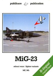


![[Profile Publications][AFV Profile 002] PanzerKampfWagen III](https://docer.tips/img/300x300/profile-publicationsafv-profile-002-panzerkampfwag_5aa21f0cd64ab225b3a0cb0a.jpg)
![[Profile Publications][AFV Profile 014] Carriers](https://docer.tips/img/300x300/profile-publicationsafv-profile-014-carriers_5aa21f4fd64ab227b349a54f.jpg)
![[Profile Publications][AFV Profile 043] Panzerkampfwagen IV](https://docer.tips/img/300x300/profile-publicationsafv-profile-043-panzerkampfwag_5aa21f47d64ab225b3a0cb0c.jpg)
![[Profile Publications][AFV Profile 047] Russian T34](https://docer.tips/img/300x300/profile-publicationsafv-profile-047-russian-t34_5aa21f91d64ab227b349a550.jpg)
![[Profile Publications][AFV Profile 024] M48Tank](https://docer.tips/img/300x300/profile-publicationsafv-profile-024-m48tank_5aa21f70d64ab226b31f37e2.jpg)