FalDi¥ . '.. .. . . i . .1 ...· 'J 1 . · . , GeorgeForty - - - - - -- ~ ... . '. ,. - -: .'; ~- " - . ' ' . - -, ~ - - , , . . . ' . :. . . "" .. ~. -...
85 downloads
120 Views
60MB Size
FalDi¥
.
'.. .. .
. i
..
1 ...·
1 .·
.
'J
,
George Forty
...
~
,
~
-
-
. '.
-
-
-
,.
-:
.
,
~
.';
-
"
-.'
:. .
.
.
,
'
..' .. ~.
""
.
- ..' -
-
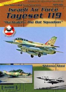
ModernCombatVehicles:5 - :-
The.
..
IrpIOn · . · .
Family
LONDON
IAN ALLAN LTD .
..
.
-
.-
-.
_.
,~
-
_
-
-,
-
-
. ',.·_7
.'
-
.
-
'
-
-
-
- -.
...
-. .
'
.
.'
_
.'-
.'
.. ~
,'.
".
-w
. '
_
,
.
First published 1983 ISBN 0 7110 1175 3 All rights reserved. No part or this book may be reproduced or transmitted in any rorm or by any means, electronic or mechanical, including photo-copying, recording or by any inrormation storage and retrieval system, without permission rrom the Publisher in writing.
© George Forty 1983 Published by Ian Allan Ltd, Shepperton, Surrey; and printed by Ian Allan Printing Ltd at lbeir works at Coombelands in Runnymede, England
Contents
1 2 3 4 5 6 7 8
9 10
11 12 13
14 15 16 17 18
Introduction Evolution On trial Production Into service Around the world Scorpion Striker Spartan Samaritan Sultan Samson Scimitar Fox Vixen Tactics Training Further Developments The Falklands
4
7
18
26
27
33
36
56
66
73
77
81
84
88
96
99
101
106
III
Front cover: A Scorpion kicks up the dirt as it races across newly harvested fields in West Germany. PR HQ BAOR Back cover, top: A Scimitar belonging to B Squadron, 17/21 Lancers of the Force Reece Unit AMF (L) in Norway. PR HQ UKLF Back cover, bottom: A Fox armoured car. PR HQ UKLF
Introduction
In the early 1970s, whilst I was commanding the Royal Armoured Corps Tactical School, I was asked to give a presentation to the annual RAC Conference, on the impact which the impending issue of the rev olutionary new CVR(T) family would have upon the tactical handling of the armoured reconn aissa nce regi ment. It probably now sounds strange to call the CVR(T) family 'revolutionary', but that was certainly the case as far as the RAC was concerned in those da ys. This was because for many, many years we had steadfastly followed the doctrine of only using wheeled reconnaissance vehicles. Other nations used a mixture of light tracked vehicles and wheeled vehicles, and even main battle tanks, but the British clung tenaciously to purely wheeled recce vehicles, such as the Saladin armoured car. This practi ce was all very well when the role of our armoured rec onnaissance regiments was just medium reconnaissance. However, since the end of World War II, armoured recce had taken on two other major roles ; namely, providing armoured support for troops involved in counter insurgency opera tions aU over the world; and secon dly, providing a major component of the Covering Force for 1st British Corps in Western Germany. The former role has over the years demanded that recce vehicles be used, not only for traditional recce tasks such as convoy and VIP escorts, route reece, roadblocks etc, but also to take over the job of main
battle tanks and provide close, direct fire support for infantry in places it was impossible to get tanks. So, in the battles in the Radfan mountains of Aden, and in the jungles of Borneo, Sal adi ns were often used virtually as tanks. For these rol~s, particularly as the enemy was unsophisticated and not very well armed by modern standards anyway the Saladin proved perfectly adequate. Indeed, its success re emphasised the need to retain some form of wheeled AFV for just this type of role and for Internal Security operations, hence, as we shall see, the emergence of the wheeled CVR as well as the tracked CVR. As far as the Covering Force role is concerned, the situation is quite different. If it ever comes to a shooting war in Europe, then the 1st British Corps, together with its NATO allies, will find itself up against a highly sophisticated, well equipped and mobile enemy, with a full range of AFVs and supporting weaponry. Although the 76mm gun of the Saladin had a good performance against armour when using High Explo sive Squash Head (HESH) ammunition, it was still very vulnerable particularl y because of its indifferent cross-country performance. It could never hope to survive for very long whilst endeavouring to impose delay on the advancing enemy, buying time for the rest of the Corps to get into its battle positions. The situ ation today is that the Covering Force is that much more capable of doing its job effectively, because it is
~ .....-:- :>.:-:
·.'.-ith full range of CYR vehicles described in You will discover, I hope, as you go through :. ~:s. exac tl y what a diverse family it is, and what ~:c : Y ':5 lethal potential is housed in such members ~::- = ~. \\'it h its load of tank killing missiles, or in - - -: :.--: , an d Scimitar and Fox with their very elTec = : ::" ,: tio nal guns. ~ : - :: '. :r. in my talk all those years ago, I did not .:: : .: o n the new and improved weapon systems of '::-';R. series, but far more upon the tremendous -=.::.:: : :.. . freedom of action which the outstanding =-:S. -::: '~. try performance of the CYR(D would give :G . s~ ~ s . N o longer restricted to roads and tracks, - -; ~ 2an go literally anywhere a walking man - ;; :. - indeed, it can even go to places a man on his : .:.:: :: ot reach, as the track pressure is less than ::' 2. com bat infantryman's size nine boots! _ : -':. ~ this unique little AFY negotiating soft -.. sand dunes, sabkha or marshland, which would ~ ;; ..... ' 5: other vehicles to a standstill, is a revelation. . . .. y book on the Chieftain tank, which was the :.: ::::5 series on modern combat vehicles, I have .::.:\' enough to persuade Leslie Monger, MBE, .. ' he opening chapter on the evolution of and CYR(W). Recently retired from the \' ehicles and Engineering Establishment ::: ::: , Les spent his early years in the commercial - : ~ ::ldustry with J. L Thornycroft and then Ley j oined the Department of Tank Design in ::.., j fo r the next two years was engaged in -: ...... .--: g some of the weaknesses of our wartime ...: ; :.. at e in 1943, he joined the team engaged on the ; - 2,na development of the Centurion. In 1948, he __ --::: : he first member of a new group specialising in : :.--: ==p r design of all types of AFYs. He continued :. -:-. :i pal engineer of the group for over 24 years, ~ ::. .-:.
~:- -::~ su pport for
- : - - ;7': :2.:1).; 5. So, in _. - . .':" i cn . and in
' :': ,e
,'.-c:aponry. :cad a good - ; Hi gh Explo :!::=~~:: -.. i' was still ~ :: .:.5 indilTerent - ;: ~'·e ~ hope to -.,.. =.. .-::.; to impose ~ =-,-:-.c '-o r the rest :: -- ' : 5. The situ _ ?' : :~~ :.s ' hat much ause it is
-. =.. .2_:....::
. : Samson, Samaritan and Sultan. Alvis t:
Scimitar, Sultan and Samaritan. A lvis
rpion, Samson, Samaritan, Spartan, Striker. Alvis
and in this capacity did much pioneering work on the deriv atives of Centurion, the FY430 family, anti-tank guided missile launchers, Chieftain, the CYR(T) family and the Future Main Battle Tank , which will eventually replace Chieftain. The group also designed tr ain ing aids and assessed foreign AFYs. From 1972 to 1976, he was Secretary of both the Concepts D es ign Group and of the Technical Control Com mittee for the joint UK! FRG studies of the Future Main Battle Tank. He was awarded the MBE in 1975 a nd now has retired to live in Camberley, Surrey. The Army, especially the Royal Armoured Corps, owes a great deal to men like Les, who have devoted their l.ives to designing our AFYs, clearly he is the bes t possi ble person I could have persuaded to tell the story of the evolutionary period. It is perhaps easy to become overenthusiastic about thi s attracti ve series of AFYs as they have so much to olTer. However, I think what really matters is that the sa tisfied 'customer' has full confidence in both Sco r pion and Fox - and this is evidenced by the com ments of the various serving soldiers of the Royal Armoured Corps, who have been kind enough to give me their unvarni shed remini scences. It has been a great pleasure for me to be allowed to rese arch this book, and to find how much of what was perhaps still wishful thinkin g when I gave my presentation prior to CYR's introductio n, has now been so fully vindicated by the inservice record of these remarkable AFY s.
5
Above: Fox armoured cars of the Household Cavalry dip their guns in salute at Waterloo station as the body of Lord Louis Mountbatten is placed on board a train to Romsey for burial,S September 1979. , Keys/one Press
Acknowledgements I have a great number of people to thank for their help and advice during the preparation of this book and for providing me with the marvell.o us selection of photo graphs. Before listing them all, however, I must make special mention of the following : first and foremost may I thank General Lewis and all his staff at Alvis Ltd, makers of the CVR(T) series, in particular Mr John Williams and Mr D. Kingsnorth of the Publicity Department without whose help I could not have begun to amass the wealth of information needed to start writing a book of this type; and also Reg Robinson of United Scientific Holdings who acquired Alvis in September 1981; secondly, in the same manner I would like to thank the Director and staff of the Ro ya l Ordnance Factory, Leeds, for their help with providing material on the CVR(W) series. Next I must thank my good friend Les Monger, for again helping me out with the evolutionary phase of CVR and for writing such an excellent first chapter. Finally in these special 'thank yous' I would like to mention Ted Flatters, Chief Photographer of the TD&PW at the RAC Centre, Simon Dun stan of the National Army Museum and Leslie Wiggs and Paul Haley of SOLDIER magazine, for all their marvellous help with photographs. My sincere thanks also go to:
Chertsey; HQ and all Schools RAC Centre, ROF Leeds, RSAF Enfield; Photo Library, Central Office of Information; SOLDIER magazine ; HQ DRAC ; RHQ RTR and RTR Publications ; Armoured Trials & Development Unit; Military Attache, Belgian Emba ssy, London.
Civilian Firms Keystone Press; British Aerospace Dynamics Group ; MEL Equipment Co Ltd; Normalair-Garrett Ltd ; NL Electrical Ltd; Morfax Ltd; FPT Industries Ltd; SG Brown Communications Ltd; Marconi Space Defence Systems Military Communications Division; Racal Amplivox Communications Ltd; Solarton Electronic Group Ltd ; Marconi Avionics; Wharton Engineers (Elstree) Ltd; Alvis Ltd ; United Scientific Holdings. Individuals Maj D. ]. M. Jenkins, QOH; Brig A. R. Douglas Nugent; Maj A. G. G. Miller, QRIH ; Col R. C. Coombes, MC (Retd); Maj R. R. Hatton, RA ; Maj R. A. McKenzie-Johnston, 17/ 21L; Capt M.]. Gloyens, RTR; Cpl A. Ferguson, RTR; Maj R. G. Jones, RAEC; Maj H. C. Starr, MBE (Retd); Sgt L. C. Watling, RTR; Maj. W. D. P. Sullivan, MBE (Retd); Lt-Col M. W. Newcombe, GM (Retd); Lt-Col P. Kaye, RH; Brig (Rtd) H. Hopkins; Lt-Col R. Osborne, RTR; Capt P. Campbell, 16/SL; Mr K. Savell.
Government Departments, Service Establishments and UnUs MOD Defence Sales; MOD Directorate of Public Relations; PR HQ BAOR ; PR HQ UKLF; MVEE
George Forty
6
--- - -
:
- --=-::- -
- -
-
-
~-
--
-
--- -
-:.
Evolution
•
-
" t'e1:l for Light Armour ~2 ~ l y 1960s whilst the UK still had defence - -_ :"'-:-, -:OI S aro und the world, particularly in the Far :.....- :-~ eco nomic situation led to dem ands for cuts in ::- : 7 o?end ing and the forces stationed overseas _: :0. J ima ry target for such cuts. To counter ,.-: : -_,' ~. to the reduction of strength overseas, ::- .:..:-: ' bega n talking of a smaller but highly =:= e- : "-1d highly mobile army that could be moved ::.. :,' 'rou ble spots by aircraft like th e Argosy. By ~ e Roya l Armoured Corps too were studying ' o2,' j"lil Y of airportable armoured vehicles for - :'::"-iegic forces, and as replacements for the _ = Sal ad in and Saracen wheeled armoured _- : e; preferably in the form of one basic - : ...:e': \'ehic le from which derivatives could be :- : ::"'..-: to meet all requirements. Tracked and -::-0 e:' i csigns were studied; the former based on the :: : -.,,0 ' 5 of the FV430 series vehicles (Trojan and - . :::: : weig hed about 13.5 tons and the latter were - -:: , :: e Saladin and Saracen and weighed no less. .. ~ - :'.',0 yea rs the designs were all judged to be too -_ ~ . ::'.:I ky. expensive and complex . -7
ROF c iral Office HQ DRAC; red Trials -.::';.; i:e. Belgian
': J ::a.-nics Group'
~.{; ~-:-.e Ltd ; NL . - : - , :::ies Ltd; SG •-:: - S,2ce Defence : Ji\'i sio n: Racal - ::: ~-: c , Eng ineers -= -:-- -.:.: Holdings.
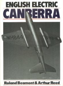
,n e airportable 105mm close support SP concept.
"I
Fig I
(,~\\,
'-\
\\' '.,
\
.\\ '
"
\ I
George Forty
.
~------------(,~\:--------
"
'
Early in 1964, an entirely new tracked vehicle design was being examined to meet a Royal Artillery requirement for a self-propelled version of a Light weight Close Support Weapon System, which was to replace the 105mm Pack Howitzer. The new light weight SP was not followed up by the Royal Artillery, but the design had so me novel features (see Fig 1). The 105mm weapon was mounted on a robust structure so that the firing reaction loads could be transmitted, via a spade, to the ground without disrupting the otherwise lightly constructed chassis. The crew, consisting of a driver seated beside the front mounted engine and three men to serve the gun, would be given only very light armour protection and would not be able to stay on-board when the gun was fired. The complete weapon system including its mounting cradle was made readily detachable, as it was thought that it could be usefully employed in the ground role whilst its carrying vehicle was used to ferry am munition to it. Unit lifting equipment or a helicopter, could have been used to make the conversion to ground role and there was a proposal for a built-in dismantling system aimed at makin g the SP self-reliant. Although the SP concept did not find favour with the Royal Artillery, its chassis evoked enough interest to be used as the basis for a family of Lightweight High Mobility Tracked Vehicle concepts, designs from which the Scorpion family of vehicles were later evolved . The Lightweight High Mobility Tracked Vehicles Concepts The vehicles in the famil y, four of which are shown in Figs 2, 3, 4 and 5, were restricted to a maximum weight of 4.5 tons and most, in the airport able con dition, were down to 3.6 tons to permit ship-to-shore airlift under a helicopter which was then being studied, or three to be carried in a proposed aircraft which eventually became the Argosy . Operation in the Far East was an important prerequisite for airportable vehicles, so a high automotive performance together with low track or ground pressure and the ability to cross inland water without preparation, were essential features of the concepts. The overall width was judged
7
Fig 2
Four versions of the lightweight high mobility tracked family concept. Fig 2: Portee anti-tank recoilless weapon carrier; Fig 3: Reece detachment carrier; Fig 4: Two-stretcher ambulance; Fig 5: Anti-APC infantry support carrier. Fig 3
Fig 4
8
Fig 5
(:--~
:, ',
., I
" T""
,-,'
~
,
, r .... - \
I
\
\
I
I
,
-).:(
I
L _'---' _ _ _ _ ....J
: - .:: riti cal because by restnctmg it to about 7ft t e vehicles would be able to pass between the - ; J i rubber trees in Malaya. The high performance -~ _:~d could only be achieved in such light vehicles ~- ..: g somewhat low priority to armour protection. --~ :,"signs used aluminium alloy extensively for its ~-_ ~ : '~ral strength and armour properties at less -:- ~ :: : ha n steel , but immunity to small arms and : : :-:_.. shell splinters was the best that could be -=~ - :-: and this was around the occupants only. When -~ : ~ :1C epts were shown to the heads of all the main ~- : .: user branches in 1964, the Royal Artillery, for he basic vehicle in the family had been _::-: ~:: ed . showed little enthusiasm for any of them and -: : :-.~-an t r y, whom it had been thought would need _: -. ·.~ h icles in a future war, still seemed to prefer to :-:: :heir feet on the ground. The Royal Armoured =-: :-:5 . \Vho had been aware of the design studies :.;: : : : he concepts were shown to the conference, saw - -: : .s sibilities of some of them as alternatives to the -=~. ::r de signs which had emerged from the recon - 2..;; 3.. ce vehicle studies of the previous three years ...:: .: ::ley were prepared to accept increased weight to :2: :-" the higher level of armour protection which ::..s :-.:eded, especially for the recce role in Europe. . -.
- . f: Requirement for an Armoured Vehicle _ =--:o nna issance (A VR) Family ::: . :Je time that the Lightweight Vehicle Concepts ~:: presented to the Army chiefs, the RAC was _ -:::. 'y drafting its requirements for a family of recon - 2..;;a ce vehicles, then known as A VRs, but later to -" ::: na med Combat Vehicles Reconnaissance (CVRs) -. :J better expressed the variety of roles in which - ,,:. were to be used. These roles were: to replace ~ 2..~ '::
planned for the next generation of armour and to provide airportable armour. The members of the family demanded were : A VR Fire Support (A VR /FS) to replace the 76mm gunned Saladin. A VR / FS needed its firepower for the traditional recce roles, for example, when forced to fight for the information it sought and to give flank and rearguard action cover for the main armour. Its arma ment, using chemical energy ammunition, had to be capable of defeating the medium armour it would meet when it was used in the airportable role. A VR Anti-tank (A VR/A T) This was to be a guided weapon launcher capable of defeating heavy armour at short and long ranges. It was needed by the RAC Recce Regimen ts in the European battlegroup and by airportable forces. It was also foreseen as a future replacement for the 13 ton Swingfire launcher FV438. A VR Anti-APC (A VR A/A Pe) The demand for a specialist anti-APC vehicle reflected the RAC appre ciation of the threat to our armour from enemy infantrymen armed with short range bazooka type anti-tank weapons who could be carried far forward before leaving their armoured transport. As more sophisticated hand- held guided anti-tank weapons were developed this threat would increase. Our tanks would be too busy dealing with a superior number of enemy tanks to take on their APCs. Liaison Vehicle This was needed to replace Ferret. It was, of course, optimistic to expect that the A VR chassis would be suitable for replacing both the 4.3 ton Ferret and the 11.5 ton Saladin . Three other vehicles were required to support the above four primary AVR vehicles: An APC to carry RAC recce troops; a Command vehicle; and a Stretcher carrier. The A VR vehicles were to make maximum use of common major components and all were to have an
9
airtransport and airdrop capability which limited their weight to 7.7 tons. All were to have a high level o[ mobility including the ability to cross inland waterways. New optical instruments were to be developed [or long range daylight recce and passive devices were required [or night movement, recce and fighting. It was required that the crew should be able to Jive and fight closed-down for 24 hours. A high level of protection was asked for, including immunity against light machine gun attack all round and against heavier machine guns over the frontal arc. Immunity was required against 105mm shell splinters from a burst at 30m, against anti-personnel mines and against injury from larger mines which would just fail to overturn the vehicle when detonated under the suspension. As much protection as possible was required against the effects of nuclear weapons and chemical and biological agents, To ask for so much in vehicles weighing only 7.7 tons
might seem like the Army indulging in wishful think ing, but it must be realised that their demands were largely based on the proposals made by the designers when they presented the Lightweight Tracked Vehicle Family concepts.
The Alternative of Wheels or Tracks The wheeled A VR designs offered were six-wheeled, all driving, and at first sight might be thought to be evolutions of Saladin which they were to replace, but they were really quite revolutionary in their concept. They offered a novel steering system to overcome the disadvantages of the existing one which, because all its wheels turned to steer, required considerable space for wheel movement and involved complex and vulnerable steering linkages and constant velocity joints. The steering system proposed was sometimes loosely called 'skid steering', but it was really much more than that. Fig6
Left and below left: The wheeled and tracked alternatives considered for the armoured reconnaissance family . Right: Diagrammatic arrangement of drives for the wheeled and tracked A R V alternative concepts. Fig 7
10
: -.; ~ "'~ 5 h ful think - - ~- :::n and s were -~ :: :. :] ,; designers ~ =--:: -=- ~ 2. cke d Vehicle
Fig8
FRONT ::-:=
FRO ~T I'-' ~
5 ~\ -w heeled,
I
USTEERIN BOX I FINA DRiV[
r 1 8,
:>: ~':o ght to be
~
~e p l ace,
but ~': ~i _ concept. ~ ~.:: ~"': erc ome the :.:... ~'C au se all its =-0 :::.o ~ e space for :: 7X :o.:".,j '. ulnerable ~:-::::- ,'oints. The ---~~ -:-; : ~;o sely called - - .: - =-.:: : e han that. :=--: : ,
--:: =
0 0 0
0 0
• "es considered
J:'!~=-"'-lk
~'rlER
PACK & CHANGE SPEED)) GEARBO
I
r...
0 ~ ~
0
0
J€1jl
arrangement
~ ee kd
and
:.:~
hy drostatic control, progressive steering was by slowing down the drive to one side whilst _::¢e-:ing up the other side, rather as tracked vehicles ; ::--:: =: al1 y do mechanically and therefore less smoothly. -.5 ::: ~ road wheels moved up and down in one plane : -_:. . like the road wheels of a tank on radius arms, it ~ :>o ssible to take the drive to each by enclosed : - ':": .. 5. The new steering system certainly increased : --: ·.'. i dth available inside the hull below the wheel-arch _- ': . bu t not enough to let the driver sit beside the , ~ :-. e at the front unless the vehicle exceeded the per - :-: d width by 12in (300mm) and as the sketch of the - ee: ed concept (Fig 6) shows, the space needed for :: -: j rives to the wheels led to a high turntable floor .: ::: :nore cramped crew space than the tracked :: ::: ept (Fig 7). The drives, shown diagrammatically ~ =-;g 8, are quite complex. The main drive from the =-- ;"'l e is transmitted, via a change speed gearbox,
:,~:_ = '. ed
through shaft a into bevel box b, from where it splits to right and left through units c and d, where the steering input is effected. Thence the drive passes through intermediate drives e and f, to chain drives g and h whose casings are the radius arms on which the front wheels lift as terrain demands. Similarly , the centre wheels are driven by chain drives k and I and the rear wheels via intermediate drives m and n to chain drives p and r. The steering pump (S/P) drives through a steering motor (S/ M) into a bevel box and thence into units c and d which incorporate the epicyclic differen tial steering system for controlling the output to the chains which drive the wheels. For some roles, for example, A VR/ FS (Fig 6), A VR/ A T and A VR/ Anti-APC, the engine could be at the rear so their width could be kept within the 7ft (2.1m) limit, but the APC and the Stretcher Carrier had to have a front engine so they had to be 8ft (204m)
11
wide. This presented a difficult choice, between accept ing two different layouts, one with a front engine and the other with rear, as had been necessary before with Saladin and Saracen, or letting all vehicles exceeed the permitted width. Without doubt this influenced the eventual selection of the tracked concepts. An exper imental wheeled vehicle was made with the so called 'skid steering'. It functioned well on road and over quite severe cross-country going, but steering was poor on grass after a frost. The wheeled liaison vehicle offered was based on the six-wheeled APC which made it a cumbersome and expensive replacement for Ferret. The tracked designs were all based on the Light Tracked Family which had been shown at the con ference held a few months earlier, so they all had a front engine and were within the permitted width (Fig 7 showed the Fire Support version). To meet the RAC requirements for protection and armament the weight was increased from the earlier 4.5 tons to a new maximum of 6.5 tons. There is no doubt that the tracked vehicle designs were too optimistic and later an extra wheel station had to be added and the weight increased accordingly, but they still had significant advantages over the wheeled concepts for all except the liaison role. Accordingly, the RAC selected tracked vehicles to replace Saladin and Saracen, for the armour needed for airportable operations and for the Recce Regiment in the new European battlegroup, but they asked for a smaller wheeled replacement for Ferret. At this stage the A VR(T) family was renamed Combat Vehicle Reconnaissance (Tracked)
12
CVR(T) - and the wheeled replacement for Ferret was named Combat Vehicle Reconnaissance (Wheeled) CVR(W). A useful degree of commonality of components was possible in the CVR(T) and CVR(W) vehicles, but they were sufficiently different to need descriptio n under separate headings. Combat Vehicle Reconnaissance Tracked Family A major attraction of the CVR(D vehicles is the com plete commonality of their automotive components, which reduces spares holding and training as well as making production more economic. The same front engined layout of automotive equipment is used for all vehicles in the family, so to the top of the engine com partment at the front and behind that to the trackline, they are built on a common chassis. Above that line the hull is designed to suit the role. Two are based on a hull which could accept interchangeable turrets housing the appropriate weapon system and crew for the role. These are: CVR(T) Fire Support (Scorpion) Generally recog nised as the lead vehicle in the family because it was required in the greatest numbers, it has a two-man 76mm gun turret. CVR(T) Anti-APC (Scimitar) with a two-man 30mm cannon turret. Three are based on a hull high enough to carry seated men. These are: CVR(T) APC (Spartan) carries a recce detachment of five plus a driver and vehicle commander. CVR(T) AR V (Samson) with a recovery winch in the rear compartment instead of the APC's five men.
:
-
- :- ~~_ o:: t for Ferret 'onnaissance ::=:-=-= -:::- : om monality - :.::.~ C \" R(T) and = ::-= .-: <>::dy different
,C
-
- - "-erl Family :: - : ': 5 is the com :=::-" i: 'omponents, - ::-.o....:::.:. .g as well as - ~~~ sa me front -:::.: ;s used for all
r--=;-. ~~ all y >-
:
-.:: .:0
':: "-S
-=~.::
a two-man
::;;."o- ma n 30mm
- -:-: ~: -
recog
~t , achment
of
:::.. '-'i nch in the
..=- - ->- :': ' "c men.
:: R(T) Anti-Tank (Striker) carries five ready-to .2 ;:1ch
Swingfire ATGW plus guidance systems" T '-'io more are based on a hull similar to the APC : _: 12in (300mm) higher. These are: :: ~ R (T) A C V (Sultan) with extra headroom needed .'~ : radios, map boards etc. : ;-R(T) Ambulance (Samaritan) can accommodate :: ; r stretcher cases. ~ e CVR(T) Basic Vehicle and Component Systems -:-:e success of the CVR(T) family was in no small -. ~ a 5 ure due to the lessons learnt during the design, - 3.:l ufacture and testing of an experimental model -. :\\'.'0 as TV 15000, which proved many of the :~.'. :u res proposed to enable the 11.5 ton Saladin and =~a c en wheeled AFVs to be replaced by much lighter :::-::0 : oed vehicles. A small dedicated team of design :-- ; i neers and constructors at the Military Vehicles ~ -;i n eering Establishment (MVEE), starting from : ' : atch in January 1965, had the experimental vehicle -_ ~. n in g by the end orthe year. At the beginning, it was -~ 2.li sed that a vehicle with the characteristics ~ ~::1 a nded could not be carried on the four wheel ::.'.:i ons of the earlier lightweight designs, so another : eel was added on each side. This was still possible - : ~ in the weight limit imposed by the airportability -",=uirements, but it did mean that the design weight - .'.2 to be held right through to production, which had - ~el y been done by military vehicle designers. Except .": : the extra wheel station the layout was unchanged : . C' :Tl that shown to the Army chiefs in October 1964. ~ ~ en without the airportability requirements, the
~
weight of CVR(T) was severely restricted by the characteristics needed in the reconnaissance role. The vehicles had to be able to move quickly and quietly over all types of terrain and inland waterways and, of course, had to be small enough to remain hidden whilst watching the enemy. If it was to get to its watching position and survive there, it had to afford protection against anti-personnel mines and machine gun attacks and as it would often have to move through, and some times operate within, the enemy or our own HE shell barrages, it needed good protection against shell splinters. These characteristics were equally important whether CVR(T) was used as airportable armour or on its reconnaissance roles, watching or fighting for information; most were also important when it was used in the other recce roles such as protecting the flank of an armoured formation or covering its with drawaL The selection of designs to achieve these characteristics IS explained in the following paragraphs.
Weight and Size The Lightweight High Mobility concepts had been designed to a weight of 4.5 tons, so that three could be carried in the aircraft then proposed or one could be lifted by helicopter. The CVR(T) vehicles had to be heavier to provide the characteristics demanded by the RAC so the air movement requirements were relaxed to two for air landing, or one if it was to be parachuted down, and the helicopter lift requirement was dropped. The transport aircraft was specified as the American C-130 Hercules, which the UK hoped to buy. Air
TV 15000, the experimental
:rude used to prove many of the C ' "R(T) design features. MoD . ' gllt: Airdrop ofCVR (W) the ." er parachute draws the vehicle _ _: of the tail of the aircraft and the •
I . faD
I
portability is a complex subject influenced by many factors the dimensions of the aircraft hold, its payload related to distance travelled, the fuel to be carried for return to base empty or with its load where landing is denied by enemy action, the effect of the concentrated load on the aircraft structure or the equipment needed to spread the load, the method of securing the load during flight and landing or for securing the load to its parachutes and taking the shock on reaching the ground when airdropped. All these aspects were studied before fixing the target weight at 7.6 tons, over which 5% was allowed for increases during development. The early research pro gramme, including the experimental TV 15000, enabled the weights of CVR(T) to be estimated with a high degree of confidence, so the lower than usual weight contingency allowance proved to be sufficient. Overall dimensions were fixed which could not be exceeded without going over the weight limit and component systems were allotted weights and sizes to suit the overall design target.
certainly be noiser than the Jaguar. They were not rejected lightly, but on balance the Jaguar had to be the choice. Later, the GM engine was installed in a CVR(T) engine compartment test rig and ran into enough troubles during its trials to confirm the wisdom of choosing the Jaguar. Further development of the Perkins engine has been so successful that it has been chosen for the 'stretched' CVR(T) or 10-man APC which will be described as a further development.
Transmission and Steering The choice of transmission system lay between a two package arrangement with separate gearbox and Cletrac type steering unit as used in the UK FV430 vehicles and the US M 113, or a single unit incor porating both gear ratio change and steering as used in tanks like Centurion and Chieftain. A third system using hydrostatic steer instead of the Cletrac type unit was also investigated because it was thought that it would provide better control for a tracked vehicle with CVR(T)'s high speed, but there was too much doubt about its efficiency and reliability in the confined space at the front of the hull. Completely hydrostatic Powerplant The time scale and volume of CVR(T) production did transmission and steering could not be seriously con not permit development of a new engine so one had to sidered for the CVR(T) time-scale. The transmission be found which was suitable or could be made so selected can be likened to a scaled down version of the without extensive alterations. The criteria for the selec epicyclic gear system which, with its hot shift gear tion of the engine were: change, has proved so successful in Chieftain. It has I - The ho rsepower in the military application had to seven speeds forward and reverse, so the steps in be near to 200. between each one are close enough to give a smooth 2 - It had to be narrow so that the driver could be progression . Like Chieftain it uses the Merritt con seated beside it in a tracked vehicle of only 7ft (2.1 m) trolled differential steering system giving turning width, so 'Vee' configuration engines were likely to be circles appropriate to the speed which is possible in too wide. each gear ratio. The ease with which CVR(T) can be 3 - It had to be light and economical because the handled has fully justified the decision to continue with whole of the powerplant together with its coolant, oil the well tried mechanical system. and fuel could only be alloted 12% of the vehicle weight. Suspension and Tracks 4 - Silent operation was important for the recon The alternative suspension systems investigated included the use of gas, steel torsion bars and rubber naissance role. 5 - Proven reliability, long life and easy maintenance as the spring media. The lightest solution was a simplified hydro-pneumatic system in which each were highly desirable. Three in-line engines showed promise. These were: wheel station was an independent sealed unit, so it the Jaguar 4.2 litre six-cylinder gasolene engine; the differed from the system in the Swedish'S' tank by General Motors 3.47 litre four-cylinder two-stroke having no external pumps, pipes or valves to intercon diesel; and the Perkins 5.8 litre six-cylinder four-stroke nect the stations and lift or lower the hull on its wheels. diesel. The Jaguar engine already developed 260hp in It had the characteristics needed for a good ride, ie the well-known car, so it could be substantially de high wheel lift, controlled spring rate and good tuned for CVR(T) with good life and easy mainten damping control, but it was an innovation which ance. In fact it seemed almost made for the criteria. needed to be proved before production started. The The fire risk disadvantage of the gasolene fuel was system was designed and made by the TV 15000 judged to be outweighed by the undoubted silent design and construction engineers at MVEE. Trials operation. The two diesels were based on com showed it to have promise, but there remained doubt mercially proven components but neither had been whether it could be developed to an acceptable tested at the required horsepower, so there was less standard of reliability before production started, so it confidence in their life and reliability and they would was discarded in favour of a conventional transverse
14
...:, : :- , ,'cen a two' - ~ ; ~ ar box and -- - :..:= Ll<. FV430
-=:;
.e:: -
-.:-:.= ::-ansmission -= ':"rsion of the
,:.: :-,:Ji shift gear - - '--': =~t a i n . It has -!;, : :- :..i c steps in et...;:.- '- ;i 'c a smooth -: ::.= \ krritt con ;'\iog turning ,
~
=-:,.-.
~~
possible in
: - =- 'R( T) can be - - :.:- ~o nt inue with
i. \'es tigated : .:.~s and rubber
~: - <.
-
; ood ride, ie and good - - , ':ation which --:: s:ta rted. The ~ ::= TV 15000 ~' ..! 'EE. Trials 7 : : =ained doubt :.: ~ acceptable - -.:::.c:: sillrted, so it ~
:~:e
': ' ,:on bar system which was estimated to be 500lb : !: :; g) he avier. Thi s penalty was acceptable provided _--: '.'. eight of suspen sion and tracks could be kept ::-,:n th e 20% allotted for it in the vehicle weight :: ':"::: si5 and this was just possible by making - ':'>::J11Um use of aluminium alloys. Three types of _' ~.::, were considered, Band tracks were rejected , :_' ~ u se of their history of lateral instability resulting - : ~ a c:k shedding and the means of overcoming this : ;:d have cancelled their attraction of lightness. _ ~ ~,t alloy tracks with rubber bushed pins were, at -=-' :. much favoured for their lightness but much -~ :-2 rc: h trials work failed to produce a reliable design. :.. ~'::tw eight steel tracks were selected for their life and -: ~ Jil i t y . Their weight was kept down by using the :::-,: techniques to cast the thin sections with a high :-:-~ ~ =e of accuracy. A new rubber support ring built -:~ :he sprocket assembly has been very successful in : : : :oming the noise usually associated with tracks : .:.:: ering on the sprocket. ~ e Hull ::, .;o n5tructing the hull as a welded assembly, using ::-: :atest developments in aluminium armour, the -: : ~ i red protection has been achieved without exceed - ~ :hc permitted batUeweight. The design of the hull : :- ':":i :1g was given special attention so that it would not -:--'-" when crossing water and would maintain the : . :~pres sure needed for the ventilating and air filtering ': s:em which is used when operating in contaminated ~ :- a s. The high level of automotive performance and -'--:-:lo ur protection could not be achieved in such a s,- ,all vehicle if it had to float naturally, so a small : _J ,in screen was added to provide the little extra : _.)yancy needed and prevent wave entry when enter ~ ; and crossing inland water.
the equipment needed to acquire and identify targets and to direct the fire onto them. In a reconnaissance vehicle the optical and electro-optronic equipment needed for information seeking is very expensive and occupies much space so it must be designed to be suit able also for target acquisition and for sighting the armament. The armaments are described in this section, but target acquisition and sighting are dealt with as part of the surveillance story in the next section, The three primary armaments used by the CVR(T) family have already been mentioned. The 76mm turret mounted gun carried by the Fire Support variant CVR(T)FS, is a lightened version of the Saladin gun. Using improved steels, weight has been saved and the breech reduced in size to suit the smaller vehicle, with no loss of gun performance. The 30mm calibre cannon mounted in the turret of CVR(T) Anti-APC was designed as a dual purpose weapon to defeat the heaviest armour envisaged for the future generation of infantry combat vehicles, so it has a useful capability against all but the front of many medium tanks, and its calibre enables it to fire an effec tive HE shell. Using clips of ammunition it has a high rate of automatic fire. The armament of CVR(T) Anti tank is the Swingfire anti-tank guided missile which can defeat heavy armour out to the longest ranges at which targets are likely to be seen. Swingfire was already in service with the RAC on the FV438 Launcher (a derivative of the FV430 series). The three primary armaments are supported by secondary 7.62mm machine guns for dealing with soft or lightly armoured targets. The turreted variants mount a 7.62mm MG coaxially with their primary armament and another on the commander's cupola. The GW launcher, like the remaining variants, mounts a 7.62mm MG on the cupola. Smoke dischargers are
e,apons ',1:eapon systems can be considered as armament plus
Below: A mock,up of the CVR (W) L, Vixen, which was never put into full production. MoD
mounted on all vehicles of the CYR(T) family to provide close-in cover. Surveillance As the rapid movement of ground forces developed, the need increased for early knowledge of enemy move ments so that appropriate counter action could be taken. Uncertainty about air superiority and about the ability of aircraft to operate in bad weather, made it unrealistic to rely too much on searching from the air and in any case the enemy would be aware of such surveillance. Consequently, passive watching by day and night from recce vehicles assumed high priority. For day surveillance, optical devices already existed which enabled a tank to be recognised at ranges out to 5,OOOm and the same instruments could be used for sighting the gun out to ranges at which it would be effective. For night operation, passive image intensification instruments were being developed which, in good starlight, would enable a tank to be recognised beyond 1,OOOm and effectively engaged by CYR(T)'s 76mm and 30mm guns. The importance of surveillance was a cogent enough reason for accepting the high price of the new sophisticated instruments in the primary recce vehicles but not, of course, in the ancillary vehicles like the ambulance, command and recovery variants. The need to use space economically in the small CYR vehicles and the importance of the crew being able to share the watching duties demanded much study of each variant before selecting the sur veillance equipment to suit it. The turreted variants had not enough space for a tank type cupola which would have given the commander all round vision and facilities for acquiring the target, laying the gun and firing it. The compromise selected for the 76mm gun turret gives a part ring of fixed x 1 periscopes to the commander and gunner so that together they have all round vision without rotating the turret. The com mander also has a sight which has x 1 and x 10 mag nification and is mounted in a rotating base so he has wide frontal vision without moving the turret. The gunner has a non-rotating x 10 magnification monocular sight which can quickly be replaced by a night sight which has high and low magnification. The 30mm Anti-APC turret provides similar facilities except that the gunner's day sight has both x 1 and x 10 magnification and is binocular. Space permitted commander's rotating cupilas on the non-turreted variants. They were not given magnified vision and their only built-in night vision was that for the driver which needed to be effective for only a few hundred metres. The commander could always use his hand held night binoculars. The surveillance needs of the APC were judged to be important so its cupola mounted a x 1 and x 10 day instrument which could be replaced with a medium range night sight. For some
16
roles, like the artillery OP, the APC could mour.: externally a man-portable radar set which had bee~. developed for more general use. Radiological survey :; an important recce task so some of the CVR vehicle; were designed to permit easy installation of monitori n~ equipment if it were needed. CYR(V\f)-Fox CYR(W) was officially described as a liaison vehicl: but its development would not have been justified if i~ had not been so attractive for internal security (IS duties and for high speed reconnaissance. So the ai rr. was to provide the characteristics needed for liaiso n. IS and recce in a wheeled vehicle using as many as possible of the components of the tracked CYR. A three-man crew was essential to make it more effectiw than Ferret for these roles and its armour had to be a, good as the tracked CYR, if it was to survive again s~ attack which had improved since Ferret was designe d. A weapon system was needed for self-protection, fo r protecting the formations it would escort and for fighting for information when used in the recce role. As no variants were envisaged which would need c: rear opening, the engine was put at the back whic r. enabled the vehicle width to be the same as the rest 01 the CYR family. Fox is a little shorter and lower tha r. the 30mm gunned tracked equivalent, Scimitar, so a, many of their components are the same and they art constructed with the same aluminium alloy, it may seem surprising that Fox is nearly two tons lighter. A number of factors contributed to this weight difference; less volume is enclosed in the hull so less equipment is carried, its radius of action is less because it carries less fuel and its suspension and wheels weig h less than the tracks, suspension and road wheels of CYR(T). The commonality of components in Fox and the tracked CYRs is greater than ever before achieved between tracked and wheeled vehicles. The Jaguar 4.2 litre engine powers them all and many other lesser components of Fox are used in one or more of the tracked CYRs. The turrets of Fox and Scimitar. together with the 30mm weapon system, sights and vision devices, are the same except that for Fox the turret ring had to be slightly smaller and the rotary base junctions of Fox and Scorpion are basically the same. Where components could not be made inter changeable it was, in some cases, possible to simplify training by using the same technology, eg by the use of the same aluminium alloy construction.
Further Developments As the development of the CYR vehicles showed thei r potential, Users who had earlier shown little intereSL realised that derivatives were possible to meet their needs. The first such derivative to be examined was a cheaper and simpler version of Fox without the 30mm
:.;.~ _\P C could mount -- : : : ,,·hich had been ~ _L...:to ogical survey is -~ ' :- :.he CVR vehicles _ =.::-....:.......<. :ion of monitoring
-
::>:'~
zs a li aison vehicle -=. en justified if it - .::- ...::.: : :11al security (IS) -;:r - :o.: ;;.ance. So the aim - --= :-: ~_ :ed ed for liaison, ~- : :: :.:sing as many as :.: ::...:: :racked CVR. A -
-2-
-r
C.5 :0
survive against
::;: :0 :~e t was designed.
x li-protection, for :: -~ .: escort and for -:-: :n the recce role. ::":ch would need a --= ;0: th e back which
;;;:c:. ::::
-
- -:0. . =:: :. Scimitar, so as - :: ::..:;,-: ;;ome and they are o ~ - - i ' m alloy, it may - _ :-0'·0 tons lighter. A - - ~- to this weight ~ - : ::-:: : :1 the hull so less - ~. =.::.;o n is less because - ' :: a nd wheels weigh 2."-. "'; road wheels of .. :~ =?On ents in Fox and - ~ : ~-er before achieved :-- :: es. The Jaguar 4.2 z:.:: ::oany other lesser ::;:; 0 :1 = or more of the : : :0 ox and Scimitar, ='-- ,::s tem, sights and - .. ~ : ,hat for Fox the _ - 0'- : : and the rotary - -~ :: a re basically the :: ('~ be made inter "=:s. ?c~ss i ble to simplify - - - :: ; y. eg by the use of
. -=
- -::- - : z... .::res showed their ::..::: :..~ :"':n little interest, ~ :~ ~ to meet their ~:.: - - examined was a - -: : x ."irhout the 30mm
::
l"
0 - :1 turret. By incorporating into the main hull the , :owage bin space between the front and rear wheels, ::.:_..: raising the roof to embrace much of the space : : . : upied by the Fox turret, a more box-like shape was .'. : nieved which could seat three men side by side, in .: : dition to the driver. The space could be used for a :.):n mand radio installation or for the modern aids :o-ing developed to improve artillery performance. " :rhough the internal volume was increased without :o..:rering the overall size, its appearance on the drawing :.)ard quickly earned the nickname of 'Fat Fox', to .\ hich the official name Vixen seems a natural ;:q uence. Vixen, like other non-turreted CVR vehicles, -.'·o uld have a cupola-mounted machine gun and 5:noke dischargers for self protection, or a sub-turret : ould be visualised as a further development of the :upola. The current strictures on defence spending :l ave not permitted the development and production of :.he Vixen concept. The second derivative to be examined was a stretched version of the Spartan seven-man APC. In this case the more extensive changes needed were justified by the attractions of filling the gap between th e 7 ton CVR range and the envisaged much heavier and more expensive MICV or Infantry Combat Vehicle, when the ageing 14 ton FV430 (Trojan) family is phased out. The designers' aim was to retain the characteristics and performance of the CVR(T) family, in a vehicle which would inevitably be heavier, without losing the logistic benefits of the family, ie simpler spares holding, easier trammg, greater reliability and more economic production. Maximum use of CVR components and technology were therefore essential. The photo shows an experimental stretched CVR(T) vehicle. The extra internal volume needed for a 10-man APC could not be achieved without a weight increase unless the armour protection was less and this would have been unacceptable. The extra weight of the larger armoured box, the extra
Above: P II, the experimental 'stretched' version of Spartan; note the extra road wheel. MoD
three men and their equipment could not be carried on five wheel stations, so a sixth was added which also enabled a low ground pressure to be maintained. The increase in length of track needed for the extra wheel station necessitated an increase in track centre width so that the steering characteristics would not be adversely affected by a higher length/width ratios. The 20% increase in carrying capacity of the suspension and tracks permitted the battleweight to be increaesd to about 10 tons, but then the power to weight ratio would have come down from 24 to 19bhp/ton if the same 4.2 litre Jaguar engine was used. However, the power to weight ratio is not the only criterion used for assessing automotive performance, because an engine which maintains its power or torque over a greater range of its speed can provide a better overall vehicle performance than one with a higher peak horsepower which falls off more quickly. The engine chosen for the Stretched CVR(T) was the Perkins six-cylinder diesel which provides nearly as much horsepower as the 4.2litre Jaguar and like most diesels maintains its torque over a wide speed range. Even in its early stages of development the Perkins diesel had been a serious contender for the whole CVR family. It has now been well proved in commerical use and has a good potential for further development. Its fuel economy gives the heavier Stretched CVR(T) a better range of action than the Jaguar engined versions. The transmission is like the rest of the CVR(T) family except that its input gears are modified to suit the diesel engine. In addition to the lO-man APC, other versions of the Stretched CVR(D, such as a Command Vehicle with more space than Sultan, or an APC which could also carry a two-man turret mount ing a 30mm cannon, would be attractive.
17
2. On trial
As with all new military vehicles, weapons and equip ment, Scorpion and all the other members of the tracked and wheeled CVR families were subjected to rigorous testing at both the prototype stage and again during early production. The main burden for the initial trials fell upon the Fighting Vehicle Research and Development Establishment (FVRDE) at Chertsey _ . now known as the Military Vehicles and Engineering Establishment (MVEE) - and the Equip ment Trials Wing (ETW) at the RAC Centre, Boving ton Camp, which has also changed its name to the Armoured Trials and Development Unit (ATDU). Every part of the vehicle was rigorously tested under all possible conditions - too many to detail all of them and give details of their results. Instead, in this chapter, we will just give examples of what took place, for example: hot weather trials in Australia and the Persian Gulf; and cold weather trials in Canada and Norway. Before doing so, however, I would like to examine briefly the vitally important job of the 'Project Manager'.
The position of Project Manager (PM) was a nel': post, given to a suitably trained 'User' when the project was first approved and funds allocated. The PM and his staff then followed the project through every stage of its development. The PM was therefore probably the single most important person in ensuring that the Army got 'value for money' in every respect. that the vehicles were up to specification, that the time schedule was maintained and that the end result was in every way suitable and 'soldier proof (ie robust enough to stand up to the heavy wear and tear it was bound to receive!). Even after production his job did not finish and he was responsible for continuing to monitor every aspect so that modifications and further development could take place. The first PM CVR(T) to be appointed was Col Charles Coombes MC of the Royal Tank Regiment: 'The idea of appointing a Project Manager, who would Below: One of the early prototypes of the CVR(T) undergoing tests on the MVEE test track. Soldier
- ::;~~
P\1) was a new when the .:: ':''''::' : 0 allocated. The =--= :"-.0 project through -=---:; ?\! was therefore - --=-::-: ~~~ 5 0 n in ensuring - ~--::. o: m every respect, --' ~2::on . that the time - -- :..: ~ ~ . d result was in - 7"- ::: ~ of (ie robust : - =2.~ and tear it was :--:: ::: .~ ~ ion his job did - : = :-(l~ continuing to -:- -~ ;: : :o ns and further - -=--=:l 5t PM CVR(T) '"' =: ~xn bes MC of the
--=-= 'e ser'
= - ~ ~2 ger, who would :-\K IT) undergoing tests
.: = oole control over a single project, began in the _ - :0: States, because of the difficulty of controlling !:'l:: _.oi\ .o projects which were often late into produc -_ 0\Uran their development budgets and then ..:.- -: G.o rform to the original User requirements. The _::: ?\! was normally given a large staff, answerable !O.: =_:: to him and housed in separate offices. Although ~ .;;' as ideal in many ways, it was very wasteful in :-: manpower and, because the PM tended to ::~o the normal chain of command, it created -::.: _:i.::al differences" at senior officer leveL In the _-:- _ ·.':e attem pted to do the same job, but with much .2..... : ~ staffs, and in my opinion, having experienced :::: o~.,. e ms, generally with more success. The PM :-,.~ T) had his own staff at the Ministry of Defence _:' J I in London and at the FVRDE at Chertsey, the ~~ - . eing the establishment responsible for the ~ ;:::.:-: ~ing . However, he was still answerable to the -:-::0f General of Fighting Vehicles (DGFVE) and _ :: ~ 1jeC t engineer was similarly answerable to the :-::0r of FVRDE. In this way the two directors still _ . ~ l: they were in proper control of the project. The -.:.:: ~ uiffe rence as compared with the old method of -.::: ::' ;ement was that the PM's team was concerned ~:. with o ne project (or in some cases like CVR(D, -_- l :-a mi ly of vehicles), and that their responsibilities _ ; ~-. \\·ith the feasibility study, went all the way .:-: _;r-. into production and continued when the !:... _ :: :-:l ent was in service. Their responsibilities ~ 7 ~:C such areas as: cost this had to be within -.,: .?.:: dow n development and production costs; time - =- ~j :1gs for development and into production had to - "-.i:1 tai ned ; performance the User requirements --.: :0 be mel. The PM also had to encourage and - :-: : .. the Sales department and then provide them - il the help possible. This became an important ;;.:: 0:- the work, as development vehicles had to be _::2:~ Y earmarked for worldwide sales demon l::.. ns. :O : : ause Project Management was a "new toy" all __ :":-_:11en ts saw it as the best means of getting their - ;-et projects accepted. The most important in my ',':as the Reliability Programme, sponsored by the i::: ! ~. This involved the monitoring by the REME !i.::..= at FVRDE of all faults, breakdowns and repairs, : :1 as ease of repair. All results were computerised :.:: ::. we were able to discuss at meetings those com =~. :s which were not achieving the stipulated =::'; c between failures. It stimulated further work on ;->onents and modifications, and kept the reliability -<.: : ~ ontinuous review, thus giving the User (both - -_- an d REME) much more confidence in the design _ .:: :': :.oping them right up to date with progress. -~l g.ome nts were made for this programme to be ~ :::: u.od into production, that is to say, when the ____ : ~ cs got to units, so as to provide information for
= =.
spares posItIoning. Another programme, introduced rather too late to be really effective, was called "Value Engineering". This involved examining the design and components to see whether production costs could be cut by altering the design, or by using different materials, or rewriting the requirement so that cheaper components could be used, or by using a different pro duction process (eg precision casting instead of machine). Although some savings were achieved for example we substituted a monocular for a binocular sight - this programme was started too late to be of real benefit to the CVR(T) programme and should have been an integral part of the development process at the drawing board stage. 'Before I became PM, the Belgian government had evinced some interest in the coproduction of CVR(T). Soon after I took over meetings began in earnest, ending in the signing of a "Memorandum of Under standing". The Belgian government undertook to buy a proportion of the total build in UK/ Belgium. Th ey also paid an agreed sum which went towards the development costs. For thi s we accepted that they would be awarded production contracts in the same proportion as the build. This was extended to the sales vehicles also. We were extremely lucky to have Col Charles de Wulf appointed as the Belgian representative. He knew a great many important Belgians, both military and in government service, and took the trouble to get to know the firms which might be able to help. The basis of working was that Alvis, who were the British producers, had to find work, in Below: P7 negotiates a jungle track during the HoI/Dry trials in Queensland in early 1970. MoD
19
the right proportion, to place with Belgian firms. There were also a number of items which were supplied by the MOD, like sights, tracks, armament etc, and MOD had to find Belgian firms, say for tracks. MOD had also to persuade some UK firms to place a proportion of their work in Belgium. This was all very com plicated, and apart from monitoring progress, much of it was left to the Contracts branches and the finance and production branches of the two defence ministeries. In the event, Belgian firms proved very good indeed, they worked quickly and enthusiastically and met all their production dates. One problem for both the MOD and Alvis was the fluctuating rate of exchange and inflation, so that, by the time a bid was accepted, the rates of exchange had altered the sums involved. Because UK and Belgium now had some common vehicles, cooperation extended to the ins tructor training schools, the exchange of ideas on training equipment (the Belgians had a very good driver trainer) and the provisioning of spares, using British Army procedures and drawing items from BAOR depots in Europe. 'Programme Evaluation and Review Technique (PERT) was the means we used to keep the project under review at a glance. The development programme was set out on charts and computer. The charts were given a wide distribution which included the User, so that everyone was aware of progress. The computer printouts showed at a glance what was going wrong and which were the aspects on which we should con centrate our efforts. We also arranged for a team to go into the whole production build up and Alvis cooperated fully. There was a whole new production line to lay down with new machines to order, install and get working. Also, after some struggles, we managed to get the Royal Ordnance Factory who were making the main armament, to supply us with PERT data. The team who did this part of the work were civilians on contract. They also later ran a modification printout which was supervised by the project engineer at FVRDE. 'I believe that the PM system was a tremendous step forward in the management of MOD projects. It worked because responsibility rested in one place, whereas previously, for example, no one knew who to blame or who should act in a crisis. Because the PM was a User, he had the confidence of the Users. FVRDE naturally distrusted the idea initially, as before everything had revolved around their Deputy Director of Tracks, who made and amended his own programmes and then got the MOD to accept them. Development engineers are not generally geared to making something that works by a set time or within set financial limitations, so they need to have some external control. FVRDE also tended, not unnaturally, to play everything rather close to the chest, and I
20
Above: Exiting from a jungle river. P7 had no difficulty in negotiating such rivers in the Queensland jungles. MoD
believe that as a result of bringing in a PM, everyone agreed that the maximum information was now readily available to all concerned, which made for better cooperation all round. Because the system was new there were inevitable personality clashes, but despite them we did make progress. One of the main reasons for much of the progress was the tremendous work done by my right-hand man, John Jennings, who worked for me for almost the whole period and who managed to get a great deal done with the minimum amount of fuss. We were of course, also very honoured when the Duke of Kent joined our staff. 'The overall plan for a family of vehicles had already been accepted before I took over. FVRDE had built a test vehicle, using available components and thanks to marvellous cooperation from everyone, the first vehicle came off the line at Alvis on time. Whilst the Scor pions were being produced work was in progress on the other members of the family. This meant a con tinuous series of acceptance meetings - first the design acceptance with a mock up and then the acceptance meeting with the proper prototype. Needless to say, after any meeting there was much to be done in the way of changes. I believe one good move on our part was to make sure that the mock up, and later the prototype, went to the various User schools well before the meetings, so that they really
cully in .lf oD
PM, everyone as now readily - : - :::2 e for better --.; SY51em 'vas new :- 2S :_ ~5 . but despite - :-- :..: ~ main reasons -~ ::- ;:n.::ndous work - : : :-.-: Jennings, who - - :: ~ :iod and who J; he minimum : - _:5'::. also very _: - :"~ ou r stafT. • ; - :::5 had already ? -- JE had built a --~ :s 2nd thanks to - _ - - 7_ :he fi rst vehicle - ; -·" :-.]st the Scor ::=..: :..-: progress on ~:.3 :::.::ant a con -~ ;S first the - ::: 2..,d then the -:- :- :::;~ prototype. _ :..-~ : Ras much to = :>7:: ~ \ e one good ~ :.: :0 : :"l e mock up, :- :: 7 ':ario us User :: :=-:2: they really
-
:
.
- 2.
: : : ' .1.
-~ :: ': alid and useful comments to make, based on their : :-. detailed examination. Predictably enough, the ~ ~.: : ! e which suffered most changes was the :: ~. :n and vehicle (Sultan), where the schools rebuilt -_- ~ ':lterior and carried out several trials over a long =- -=~0d before they were satisfied. Another area which :0.0 ..::ft almost entirely to the User was stowage. They - ~ :: e their own lists, but instead of FVRDE (and later ! ':::: E) doing the work alone, the User came up to :=': ~ DE for about a fortnight and went through every :: :-: ; with the design stafT. This forestalled endless :- : ,; ~ri ng at acceptance meetings about what should :~ , :owed and where, since they had more or less : : ~ ed it all out for them selves already. This was - : :e difficult and time consuming when more than : - :: e ser was involved, for example, I remember that :~ :~ the Gunners and the Infantry were involved with . : -:-.c of the vehicles in the family, as well as the RAe. . :: also had to have the RAMC in during the design _.. S2marita n, the ambulance. The first prototype Scor =- : :-: came off on time (by some miracle!) and the : :"-.;;: 5 followed more or less on target, all pro ;-::3s i\'ely more up to date. Also, our development -"- ~! c e was fairly well on target, Syd Barton, the ~:.: Llr MVEE Project Engineer, kept a very tight hold _: ~ :s end which was all important. However, by the :"-.e we came to production, inflation was hitting us -~j and the vehicle price was well up. There were :- ~ . lems a lso of the speed of production, so we were - :ontinuous conflict with the MOD who wanted ::-.' -::les to equip units, whilst we wanted to supply
them to overseas customers, who were clamouring for them and would pay cash! 'Very early in the programme we sent two Scor pions out to Australia by air, in the hope that they would place an order, also to enlarge the scope of the vehicle trials. They certainly performed very well. It was on this particular trial that we had an unfortunate accident and an Australian soldier was killed when the track broke and the vehicle turned over. I'm sure that had there been no PM the whole project would have been set back at least a year as a result of this unfortunate affair. As it was, we had already built up a lot of confidence in the vehicle and I managed to get agreement to continue work, although the mileage which a track was allowed to do was cut down and a stringent inspection was introduced at frequent inter vals. I believe it is on occasions of this sort that the PM system really shows its worth. There were many incidents during the development which could have stopped the whole show - but were straightened out because of the very close cooperation we had with the General Staff, MVEE, Alvis etc, and a quiet word with DGFVE prevented the usual awful escalation of prob lems to high levels! We sent vehicles to Abu Dhabi for desert trials, where quite unknown problems cropped up. For example, the idler (at the rear) fell ofT when it repeatedly hit the bottom of sa nd dunes and had to be modified. The Lebanese also had some vehicles demonstrated to them and were particularly impressed by the performance of the Squash Head ammunition for the 76mm gun. I think the most impressive demon stration was the one in Iran, where two Scorpions were flown out, moved off directly after landing and did an excellent firing demonstration. The crews in all cases were from the Royal Armoured Corps Centre. Vehicles were also taken by sea to West Africa, on the MOD's demo ship.' Trials As the Project Manager has explained, tropical trials for the Scorpion and Fox, took place in Australia in 1969-70 under the codename of Exercise 'Corinthian'. Two prototype Scorpions were flown to Australia by C-130 Hercules and landed at Mt Isa on 20 November 1969. During the trials period one Scorpion did 3,488 miles (5,580km), the other 3,189 miles (5,13Ikm) and both performed very well. Two engines, a cross drive and two fan units were changed during these trials. There were no significant gunnery problems. Basically the trials comprised : a hot and dry trial from Nov ember to December 1969 and a hot and wet trial from January to May 1970. They included dust trials, mobility trials over sa nd, swamp and jungle paths, and jungle storage for 28 days in a rain forest (the vehicle started first time with no problems!). The results were adjudged as being most impressive and fully justified
21
the decision to advance the tropical trials by one year.
Apart from certain track problems (already mentioned
by the PM), there was a high degree of automotive
reliability. Crew compartment cooling under high
temperatures proved totally inadequate and led to a
special cooling system being installed for later trials in
the Persian Gulf (mentioned later). One of the trials
officers in Australia was Capt (now Lt Col) Patrick
Kaye, of the Royal Hussars. He wrote the following
short account of his visit 'Down Under' in the Royal
Hussar Journal, under the appropriate title of , Porn my
Mania 1970':
'Shortly before I was due to take up my appointment
as GSO III Weapons at the Equipment Trials Wing,
RAC Centre, I received a letter from them. " Welcome.
Great to hear you are joining us (followed by some
more platitudes; in paragraph four was the meat of the
letter). Within six weeks of your arrival, you are off to
Au stralia on a hot/ wet and hot/ dry trial in Queens
land, you lucky man" (more sales talk).
'Highly pleased to hear all of this, I swallowed the bait and sales talk . Visions of Fox and Scorpion sand trials on Bondi Beach, Sydney, leapt to mind. One could drop down to Sydney, Bondi, Birds etc, for the weekend. It was not until I landed in Australia on 15 October 1969, that some of the enthu siasm faded. I had failed to look at the scale of the map. Sydney to Mary Kathleen, North Queensland , was just 2,500 miles. The flight from Singapore to Sydney lasted for 7t hours, of which four hours was spent flying at 550mph above Australia. A further 3t hours saw us in Townsville, the second largest city in Queensland . 'On arrival in Townsville two weeks were spent meeting the 56-strong Trials Team, and collecting the Fox vehicles, stores and spares from Brisbane, 1,000 miles to the south . The team consisted of seven officers, one doctor, two RAC officers, one RAAC officer, and the remainder were collected from ETW Bovington, civilian and military crewmen and fitters from FVRDE, cooks and a medical orderly from Singapore, a detachment of JOth Gurkhas from 15 RAAC soldiers and an Alvis Penang, representative. After this acclimatisation process the trials team set ofT 550 miles westward by metalled and dirt road to Mary Kathleen. The four-day journey passed without incident despite temperatures in the hundreds. I took the advance party by narrow gauge railway to Cloncurry in the most fantastically ancient "Well's Fargo" type carriages. Due to the single-line track, with the driver hopping out at frequent intervals to check whether the line was free, we covered the first 78 miles in 5t hours. They boasted no buffet car, restaurant or bar, and this gave one a foretaste of future conditios. My fellow Australian travellers solved the problem by carrying cases of six ice-cold stubbies in an Expanded Polystyrene Eskies. These
22
Above: Jungle storage: after a long storage period in the jungle this Scorpion started first time and showed no ill effects. MoD
were replenished at every station. The empties were hurled, in true Australian style, from the train .... 'The two Scorpions were flown out from England in a C-J30 Hercules. On their arrival, work on the hot/ dry trial started. The arid and hot country around Mary Kathleen was dotted with both small and large copper mines. The former were operated by one or two men, earning on average £5 ,000 a year per head pro vided the copper content of the rock was high enough . ... After Christmas the team drove a distance of 700 miles to the hot/ wet area on the east coast at Cowley Beach. It is an extraordinary quirk of nature that two nearly adjacent areas can have such varied climates. Mary Kathleen produced dry heat conditions which averaged 105°F and rose on occasions to 114°F. There had been no rain at Mary Kathleen for four years until a week before we left. In contrast, the Cowley rainfall was 25-30 inches a month with 6-10 inches in 24 hours. Temperatures of 85 0 to 90°F with 100% humidity were normal. ... At Cowley the team was put into a tented camp erected for us by the Australian Military Forces. Their Tropical Trials Establishment is based on the beach at Cowley. Miles of beautiFul sandy beaches, but swimming is forbidden. Box jellyfish, stone fi sh, sea snakes and other friendly marine life abound. The jungle echoes to the sound of the Cookaburrah, the laughing bird of Australia. Snakes are not uncommon. Taipans, Brown Snake and Death Adders. The first recorded case of a white faced Gurkha teetotaller, seen drinking a glass of neat rum, was recorded after he found himself sharing his bed with a Carpet snake! .. .'
: ... mr ast the first cold weather trials took place in :=:-:- ::::7lber 1970, and were known as Exercise Prairie _ - ]'.': . They were held at Camp Wainwright in .. ~~ a. Two Scorpions (P6 and P I I) were moved by :-: :~: ' les from RAF Lyneham. Both vehicles perfor -7 :' excellently throughout the trial period , P6 -:;. s:ering a total of 1,431 miles (2,290km) and Pll : -: miles (3,160km). A brief outline of the pro ;:-~ :-:-. :n e of tests was: Week 1 acclimatisation of :~ . : -,n nel, stowage of vehicles, crew training of ::: -'-..-.a 'i an crews, Arctic training for British personnel. :-::..: 2 - vehicle performance trials. Weeks 3 and 4 - lDto motive trials, including a cyclic mileage trial, - : ::-': :::ield day habitability trial. Weeks 5 and 6 7~::v n s and tactical trials. Weeks 7 to 10 further __:: ::lOtive and vehicle handling trials. Week 11 ~-.:.: jerformance trials. Further Arctic trials were held .. : years later between 3 January and to February - -.: . in Norway, and were performed by men of the ; _0; a nd Royal, plus representatives from ATDU. ,,-:: : types PI 2 and P 13 were used and the trial was
- ~. <' empties were .=-:- ::-.e tr ain .... - :: -: :'~ o m England in - -- - ~ . work on the - - : : .:-o un try around - x :...: s:nall and large ~ - ""- ~ ~ j by one or two : : :':;: . er head pro::':: 7 ~ -, k was high -~. - 2 ~O \'e a distance :: - ~.~ east coast at -::...-: :Jui rk of nature :.!: .: ?Xe such varied -= :..! Jeat conditions
= ;;--'-- ::-: con trast,
the . ~ -:: '. th with 6·10 - -=: : (0 90°F with -.: ~ _ "ley the team ~:- -.:: fo r us by the -. ~ ~~ o pic al Trials ::- ~ : Cowley. Miles ~ - ~ ~ is forbidden. ~ ':.:: : Lt her friendly . :~ : he sound of _ - -: l :- Australia. -- ' -'- B ~own Snake ::.::-.:: :.=..o e of a white - ; :! ~ I ass of neat .:: .:.:::-.;.::::- sharing his
=-
:-,
,
c_
\
\ \
\
conducted as part of the normal training of the Force Reconnaissance Unit AMF(L), during Exercise Hardfall, 1972. As Col Coombes explained a CYR(T) Sales Team vi sited Abu Dhabi and the Lebanon in March 1976. The leader of the party was Maj David Jenkins of the Queen's Own Hu ssars and he writes : ' In March 1976 I was told that I was to form and lead an RAC Sales Team to take Scorpion to Abu Dhabi. The purpose of the visit was two-fold - firstly, it was hoped that the Abu Dhabi Defence Force (ADDF) Armoured Car Regiment would buy the vehicle, and secondly, that we would be able to carry out hot weather and sand trials. At the time I had no experience of Scorpion, but I gathered a team of 10 soldiers and two REME technicians at A TDU in Bov-
Below: P6 negotiates the cross·country course during Exercise 'Prairie Snow', the cold weather trials in Canada in December 1970. MoD
ington and carried out a short but intensive period of training. We took one production and one pre production vehicle which had been modified to take an air conditioning unit manufactured by Normalair Garrett (see Chapter 5), and we were accompanied by two specialist engineers - one from Alvis and one from Normalair-Garrett. 'The Abu Dhabi visit was scheduled to last for just over two months and to take place during the hottest time of the year. The team had to take with it all the spares that might be required, plus tools and ammuni tion. As we had no experience of what would be required, we necessarily had to rely on "best guesses" . The stay in Abu Dhabi involved three stages - first a shake-down period on Abu Dhabi island, followed by the automotive and gunnery trials. During the shake down period the team gave static demonstrations of the Scorpion to members of the ADDF whilst they got used to the heat and did some preliminary sand driving. We concentrated on driving in soft sand and sabkha. Sabkha is the type of desert encountered on the coast, where a hard salt crust on top of the sand gives the impression that the going is good and firm. However, once the crust is broken, the ground becomes soggy and wet and is very difficult to cross. The temperatures were high during the whole period of the stay and maintenance was always difficult as tools got almost too hot to handle. 'The automotive trials took place in the sabkha by Tarif and then we turned south into the desert to go to ADDF squadron locations in Bada Zaid and on further into the desert. The sabkha trials were an immense success. We set Land Rovers and Scorpions off over the sabkha and each time the Scorpion got through while the Landrover bogged, the light ground pressure of the Scorpion proving its value. We then set off south into the sand. At first the going was easy over gravel and sand up to Bada Zaid, but we then went into an area of sand dunes about 200-300ft high and of soft sand. No tracked vehicle had ever been there before and it is not easy to drive in soft sandy areas. The sand can get between the track and road wheels and as a result the track is thrown. It was necessary to go very fast down a dune in order to have the impetus to reach the top of the other side, because once you stopped on the way up a dune, you risked the chance of sinking into the sand. The result was to hammer the suspension when it hit the rising dune. We found we cracked the rear idler wheels, but subsequent redesign has now strengthened them. It took us only four days to get to the ADDF desert camp, but 10 days to come back, as we were going up the steep lee side of the dunes. During this period we had to change a gear-box which took two days as we had no crane and everything had to be manhandled by the crew. However, we returned safely to Abu Dhabi for a rest
24
A;'ove: A Scorpion crossing sabkba near tbe coast near Tarif, Persian Gulf. Major David Jenkins Above right: Scorpions pause at the top of a mountain pass outside Beirut. Major David Jenkins Right: Scorpion negotiating paddy fields in the Far East during a comparative trial with other light tracked AFVs, in which CVR(T) came out top. A {vis
before the gunnery trials at EI Ain (Buraymi). These proved very successful and culminated in a firing and driving demonstration to the ruler of Abu Dhabi. We had proved that CVR(T) could be operated in the heat and that it was excellent in sabkha. We had gone further into the desert than any other tracked vehicle, and although we had some problems, had managed to complete everything successfully. ' Following the Abu Dhabi trial we went on to Cyprus to refit the vehicles. We then gave a short demo in Cyprus before going across to the Lebanon. Again we put Scorpion through its paces giving gunnery and automotive demonstrations. Compared with Abu Dhabi the going was very easy and we had no problems going from sea-level in Beiruit to the mountains behind. We demonstrated HESH shooting against a pillbox near the Israeli border and fired on a range that backed onto the Syrian border - so we had to be very careful not to miss the targets! After four weeks in the Lebanon we were airlifted in an RAF Belfast back to England.'
+
.
r;
;
~"'I'
-1L~lI&!fl:r ~~:'.::!-
.. ~,~.
near Tarif,
- lai n pass outside
r ZJ East during a ?t
- -
So..
which CVR(T)
3 ·~ra \" mi) .
These
- - _:~.: On ~ firing and
- :: ...,." u Dhabi. We --: : : e -,":ed in the heat \Oe had gone
::a ked vehicle, -.20 managed to , wen t on to -, -:- - ~- - a\e a short ~::~ .:~ ;he Lebanon. aces giving - ~_: ~os. Com pared '~'\. and we had -=. ~ ikir uit to the -~.: :-::tSH shooting _:- .:~~ nd fired on a - :::':'er - so we .-~ · e.r2oets! After ~~ -::::=:~ i n an RAF
-'
.....
.. ,""":."
;
.-'
3. Production
In September 1967, Alvis Ltd of Coventry, won the contract to design and develop the CVR(T) series and this was followed in 1970 by the first production order. Alvis was of course no stranger in the field of manufacturing armoured fighting vehicles, having already been responsible for the Saladin armoured car, the Saracen armoured personnel carrier and the Stalwart high mobility load carrier. In total the company had produced nearly 4,000 of these wheeled armoured vehicles. Its main works are at Coventry, on the Holyhead Road north-west of the city made famous by Lady Godiva's ride and batlered in World War II by German bombers. The facility site occupies some 23 acres, and includes the principal machine shops, assembly lines, design and development facilities, together with such necessary support as laboratories, X-Ray, Tool Room, and Heat Treatment Shop. The main test area is on 40 acres near Coventry airport at Baginton and includes 1+ miles of vehicle test track. The main machine shop is equipped with a full range of machine tools which can carry out all the necessary operations on components for the full CVR(T) range, CVR(W), and also on aero engines (as long ago as 1936 Alvis produced the first of some 2,300 Alvis Leonides air-cooled radial aero engines, in addition to their company's world famous thorough bred motor cars). Spares are also manufactured for all these equipments as well as for the old Saladin range, and for the Stalwart load carriers and the Ferret scout car. The No 4 Machine Shop has a comprehensive range of numerically-controlled machines for machin· ing the aluminium armour plate and components used in CVR(T) and CVR(W). The firm now has extensive experience in the welding of aluminum armour and some of the procedures they use are unique, welders being trained to a very high standard (based on QAR
26
0021 specification). Specially designed automatic equipment is also used for long welding runs. Assembly lines are in operation for all the CVR(T) series and also for Fox turrets. One shop is devoted to the detailed assembly of such components as gear· boxes, final drives and wheel stations. Alvis Quality Assurance is approved to Defence Standard 05-21. The Tool Room has the very latest precision machines and includes a temperature-controlled shop with jig borers capable of working to very fine tolerances. A plasma arc plate-cutting department contains the latest type of photo-electrical control equipment for cutting all gauges of aluminium armour used on CVR(T). In addition to a comprehensive range of laboratories, there is a mock-up department able to provide full-size wooden models; plating and paint shops. Production After building the original 17 prototypes, the first of which was completed in January 1969, Alvis was awarded the production order for CVR(T) vehicles for the British Army in May 1970 - an order amounting to some 2,000 vehicles. Five months later there followed an order for approximately 700 members of the CVR(T) family for the Belgian Army. Various components are built in Belgium and the main Belgian factory is at Maiines. Export orders have followed these two major contracts and have included vehicles for Iran (prior to the coup), Brunei , Nigeria, the Philippines, the United Arab Emirates and Tanzania. As will be seen later, various CVR(T) components are now also used on other AFVs. In September 1981 Alvis was acquired from British Leyland by United Scientific Holdings who continue to produce and develop the range of Scorpion family vehicles.
4~
--:- ~_ =d
automatic -J.-c1ding runs. -: - .:C th e CVR(T) ~ : - ~_ :s devoted to
-- ~
-
"- :cst precision - :- -: _ trolled shop - ; : 0 very fine ----=--:. ; department - :~ :- :::ical control - - -=- _:::"_:nium armour -: ~ ;: mprehensive - ;: : - .~? department - - : ':::-:5: plating and
~l e
Into service
first regiment to be issued with the Scorpion in the 3:-itish Army was the Blues and Royals, then stationed ~: Windsor, in early 1973. They were followed by the : - th/ 2Ist Lancers, at Wolfenbuttel, West Germany, in _-,- ie 1973, and then the 14th/20th Hussars, at Herford, -''. est Germany, in early 1974. Brig Arthur Douglas "\"- gent, when he was commanding his regiment, the : -th/ 2Ist Lancers, recalls those days thus: -TJ e 17/21 Lancers first took delivery of the Scorpion ~: Wolfenbuttel in 1973. There was great excitement -,;. ':en the first vehicles arrived to replace our ageing Sa.ladins and Ferrets. Two squadrons were soon :-:{u ipped and after a winter of individual training, took : a rt on Exercise "Glory Hawk", with the 14/20 :--Iussars, similarly equipped, on a fine area to the north ..:oj- the Moselle. This was the first real test of the vehicle which performed marvellously well and there were
very few breakdowns. The drivers really enjoyed themselves as they motored up and down the steep and wooded hillsides, going to places which their wheeled counterparts would never have achieved. It took some time, however, for the full potential of the vehicle to be realised. Long experience of the wheeled Saladin had conditioned commanders to driving on roads and tracks. A more positive directive had to be given to persuade them to take to the fields and to chance their arm across country . The damage done was negligible, as the track exerts less pressure than a man walking and so the whole of a vast area of farmland was avail able manoeuvre. The Scorpion was shown off to the Below: 'Hello One One - this is One Two'. - A Scorpion of the 17th/21st Lancers relaying information during Exercise 'Glory Hawk' in southern Germany. Brig Arthur Doug/as-Nugent
the first of _ : ; 5 . Alvis was ~ :-' - - ) \-ehicles for - - : - .: ~~ amounting - :- :_:..5 later there - _ - - j members of - -!>-~y . Various - :.-:- ::Jai n Belgian ~: ':a\-e followed =-~ 'ed vehicles ~ - - -=:., ~ i geria , the -~ :;:: Tan zania. : ~ :::po nents are - -:: -;7 5_
:- -=
-'-: -
:: co ntinue to Ion family
- :~ -_
27
Press during this exercise and at one stage a ball point pen was run over without damage. The Press were also most impressed by its climbing ability which nearly ended in disaster owing to the over enthusiastic efforts of the driver! Another highlight of Exercise "Glory Hawk" was a trip around the West German Grand Prix motor racing circuit, the Nurnburgring. Scorpion performed with distinction, breaking the lap record for a tracked vehicle! 'One drawback of the Scorpion was the lack of stowage space for the crew's personal kit. This was particularly difficult in the troop leader's vehicle, as for some reason young officers always seem to bring enor mous suitcases on exercises. In the early days the vehicles looked rather like tinkers' carts with all the impedimenta tied on to the turret. Unofficial bins were tied on, welding being difficult owing to the aluminium construction. Finally an official modification was introduced which put a large bin at the back and that went a long way to clear up the "Christmas Tree" effect. Even so the Scorpion, particularly with a full load of ammunition, has very little space for all the gear required by the crew. I remember too that spare parts were initially in rather short supply. We had some problems with the oil seals in the gearbox and replacements were very slow in coming. It was explained that the vehicle had been issued early to get it to regiments and that a risk had to be taken on spares. Also, until Ordnance had had User experience,
they were not prepared to scale for spares. I am sure that this was a mistake though we did benefit by getting the vehicle earlier than we would have done. 'The annual pilgrimage to the Gunnery Ranges at Hohne went off well with less than the usual number of problems. Because the gun was similar to that Saladin. little retraining was necessary. The vehicle handled extremely well and gave a creditable if not scintillating performance. The rather looping trajectory of the HESH round makes correct range estimation absolutely vital and at first many errors were made. A rangefinder would have been a most valuable addition. Equally, in the early days, vehicles were not equipped with a II night sight, so that observation and shooting at night were only possible using white light from another source. 'Another excitement was the swimming of the Weser River, at Ohr Park upstream from the famous old town of Hameln (Hamelin). It was laid on with a fine organisation and plenty of preparation, but it must be admitted that it was not a great success. There was a four-knot current running and relying only on tracks for propulsion, meant that forward movement was hard to achieve when exiting. The vehicle did however
Below: Close· up of a group of Scorpions, during an exercise lull in BAOR. Soldier
: - " -: ::' ~c S.
I am sure
=- ':id benefit by
: -_:: ~a \'e done. -; -:..:, :~y Ranges at :: -= ~ ,,'j al number of - ~- :0 ' hat Saladin, ~-= '. f: icle handled - ~ :' ~, ,)t scintillating f :::-?',;;;:tory of the ~, ; c estimation _ -: - : : 5 '.':ere made. A - .: c..::Ja' Ie addition. =~; no t equipped - ::._ ~, and shooting ~~ t c light from ==
:-:", -
'ng of the
- :': :n the famous
'..S :aid on with a 7""::: 2:':on. but it must - - ~ ~-=5 S , There was _..:. ~ o nl y on tracks ~ : ~, o \ 'ement was --. :.:..:-~ = did however
swim and the exercise was certainly valuable if not very convincing. * 'A parade was held later in the barracks at Wolfen buttel and the salute taken by our Brigade Com mander, Brig Martin Sinnatt. Scorpion lapped round the camp at a good speed and made a most impressive impact on the parade. Also in the audience was "Miss 17/21 Lancers", who had previously been elected as "Miss Sherwood Forest". She too had the chance to drive Scorpion. I believe that the Scorpion was accepted into the family of the Regiment quicker than any other vehicle. It went well from the start, was liked by all the soldiers who served in it and was ideally suited to the job of reconnaissance, which it was required to do. It was indeed a soldier's vehicle, the right one for the job.' *CVR(T) can of course be equipped with additional aids for swimming now, including applique propellers which greatly improve waterspeed.
Left: On watch. The commander of this Scorpion clearly feels that two pairs of eyes are better than one! Soldier ,,':ercise lull in
Below: A line of Scorpions carrying out some blank firing during an exercise in Gennany. Soldier
Top left: A half-troop of Scorpions in a non tactical leaguer in the outskirts of a German wood. Note the 'Fahrschule' (driver under instuction) plate on the ITont., plus the Union Flag. Soldier Centre lert: Getting ready to kip I A young troop leader of the 14/20 Hussars unpacks his kit., having laid out his sleeping bag to air on the top of the bivouac. Soldier Bottom: 'We're going to hang out the washing ... '. 'Exercise ends' means a short pause in training for this Scorpion crew and 8 chance to wash some of their kit. S oldier Top right: Bucking like a bronco, a Scorpion accelerates across a stubble field. Soldier Top far right: Two Scorpions of the 17/21 Lancers shows their speed around the Nurnburgring after an exercise. Soldier Below far right: An excellent shot of a Scorpion moving along a German road during training. Soldier
hi s kit, having laid : b2g to air on the top
S oidier " , 'going to hang , . . , '. 'Exercise
. 5 lik e a bronco, a
• "'==-=.::,::.es across a -:-lOD Scorpions of the ~..s [heir speed --:-...r'gring after an
;;-,ceUent shot of
•~
'I,!;."l.
~ ~,-:,
'01
J~r.'"
:
.. ,.
' ' "'5 '"'
;.......~' ~
"..- • ~.::_~1.f'i~.
- .. -;.:.:.; :" .\~ ,
,
O ne of Arthur Douglas-Nugent's young troop leaders '. ':as Robert McKenzie Johnston. He was also kind =nough to give me his reminiscences of the first days of Scorpion in the Regiment and he told me : 'One of first things you notice about Scorpion, =specially after a career on tanks and Saladin, is its speed. There you are at the traffic lights, a large \ fercedes beside you, and as the lights change you pull aw ay together and stay together all the way down the ~ oad. It does something for the British image. But speed like this does lead to unexpected problems like maps, for instance. There is not just the difficulty of map reading when little errors become enormous ones in seconds, but the difficulty of refolding a map as large as a tank sheet at 50mph on a bumpy track. Every move seemed to need three or four refolds during the course of it unless you were an origami expert. But the speed had compensations - mobility was improved considerably : not only was the Scorpion al lowed into areas where no other tracked vehicles had been allowed, opening up new exercise possibilities, but it was also able to go where no other vehicle had been able to go before. We did an exercise early on called "Lobster QuadriUe", where our aim was to infiltrate behind the enemy. We achieved it by driving up a river bed at night, a route the enemy had not anticipated anybody using. You could motor along at \'ery low revs making it very difficult for anyone to hear you, or to place you if they could hear the engine. 'With these advantages there was also the sighting equipment. Together they meant that for the very first time we used the vehicle as the rule rather than the exception when in an OP (Observation Post), which was very much more comfortable for a start and much more practicable. There were other little things about the Scorpion th a t we all liked at once. It had a heater, it required very little routine servicing, it had a magic tool kit (sockets and ratchets, what a change from Saladin), it had an even more magic bivvi.* Of course there were ticks. Stowage was a big headache after the
roominess of Chieftain and even Saladin. Big men felt wedged into it, a nd there just seemed to be no room at all for one's kit. We improvised, fitting jerrycan holders onto the back bin and leaving off things we hoped we wouldn't need . But when we were issued with five days, food and ammunition on one exercise, well , we just had to give some of it back . 'Aluminium was a soft metal. Every time we hit anything, even gently, like a tree in a wood, the floata tion screen came off. Was it 168 nuts and bolts ? And it never went on again easily, the chassis seemed to deform while you watched! And those engine decks! r think they a re hinged now, but we used to have to undo the bolts and lift them off even for halt parades. Someone always managed to drop a corner on to the radi ator and hole it. ' Firing the gun was quite an experience - such platform rock that it was very difficult to maintain a point of aim. And bad luck on the commander who forgot to move hi s head away before the gunner *Bivv i= Bivouac. Each AF V is equipped with a tent-like tarpaulin which can be attached to the side of the vehicle and produces a very snug and waterproof shelter for the crew.
31
Right: Two Scorpions crossing a tank bridge during the tactical display at the RAC Open Day, held at the RAC Centre, Bovington Camp. Simon Dunstan Below: Scorpions of IRTR cross the River Weser by M2 bridge during Exercise 'Mizzen Mast'. PR HQ BA OR
shouted ' Firing now!', for the hard rubber eyepiece around his sight used to leave its mark on his face and the bridge of his nose. The first day's firing always brought its crop of inexperienced commanders who seemed to be wearing goggles permanently! We had to fire over the back decks to begin with - we were told it was to let the instructors stand on the engine decks behind us, but I believe it was because the blast from the gun blew the flotation screen out. 'Small details have changed on the modern Scorpion from those early days. Most of our first ticks have been solved, especially stowage. But those first impres sions, the speed, mobility and adaptability of Scorpion, they will remain.' CVR for the RAF Regiment It is interesting to see that the British Army is not the only Service to be equipped with the CVR(T) family of vehicles. The 1979 Defence White Paper contained a number of improvements to be made to the field squadrons of the RAF Regiment, who are charged
32
with the defence of RAF airfields, currently a key area of concern to NATO. As well as improving their ground-to-air capability by introducing the DN 181 'Blindfire' radar for their Rapier fire units, it was decided to mechanise the six permanent airfield squadrons, by equipping them with CVR vehicles. The hand over of the first RAF Regiment CVR(T)s took place at Catterick in August 1981. These 'Light Armour Squadrons', as they are now called comprise three combat flights of Spartan APCs and one flight of Scor pions. Other squadron vehicles include a Sultan command vehicle and a Samson ARV . The AFVs replace the old Land Rovers, and have significantly improved the Regiment's mobility. This is essential when one remembers that a squadron can have the responsibility for an airfield perimeter of 40 miles (64km) plus in length, and an operational area to protect of some 225sq miles (360sq km). The 76mm guns of the Scorpions provide the squadrons with more plentiful and much more accurate direct fire support than the 81 mm mortars, which were their only comparable weapon systems.
6. Around the world
a
.,. --
"Y '
-----, i ;,-
..
.
" <" ,.~ • A ' .. • _ " _
-:,~
___~~ tly a key area :os :mproving their _:_:in" the DNl8l ~ units, it was _:-=~ ane nt airfield :.: C\-R vehicles. The - .:- ==: CVRCT)s took ~:::. e-s;'! ·Light Armour o mprise three - :: .:' .--: ~ fl ight of Scor - :'"; _-:-::ude a Sultan -~~ \ .. The AFVs ;:- _-2. ' ·c significantly ~ :u s is essential -2:::_''--: can have the -=-....--..;::. :-:e ~ of 40 miles - : =~~ :nio nal area to The 76mm - - :.:;:- s<:j uadrons with 2-:-: ~ ~a t e direct fire -_ ;~. were their only
::::0
Above: 'On your marks' - a pair of Scorpions of 17/21 Lancers receive the chequered flag to start them off on a circuit of the Numburgring. Soldier Left: Has the driver popped in for a quick one? A Scorpion in Soutbern Germany during training. PR HQ 41h Armoured Division
.: -=-:". ).
33
Top left: A Scorpion of the Blue and Royals is used as an observation post during peace-keeping operations in Cyprus, December 1974 (note the large Union Jack on the front of the AFV). COl Below left: A Scorpion belonging to the Belgian Army is seen here during a parade at their Armoured Corps headquarters. Belgian Embassy, London Below: A Scorpion negotiates a rocky wadi in the Persian Gulf. (Note the 'L' plate.) Alvis Right: Three Scorpions of the 16/5th Lancers on a medium girder bridge in Hong Kong, November 1974. COl Below right: A Greek farmer looks on as a Scorpion of the Blues and Royals passes by. This was a scene during Exercise' Alexander Express' held in the mountains of northern Greece in June 1973. PR UKLF
34
sal as an r : :I~=n::;s ln
Cyprus, - tl::e front of the
..\rmy is seen here
- - ;he
Persian Gulf.
a medium girder
6. Scorpion
General Description Scorpion is a small, fast light tank, probably the fastest and smallest in the world. Its most outstanding feature is its ability to move rapidly across country, thanks not only to its high cross-country speed, but also to its exceptionally low ground pressure - less than that of a man walking --- so that it can tackle difficult terrain such as bog land, paddy or soft sand with the greatest of ease. The vehicle's small size makes it a difficult target to hit and ideal for taking cover behind small folds in the ground. It is thus perfect for 'hit and run'
delaying tactics, such as are currently practised by the 1st British Corps Covering Force in West Germany. Being light and compact it is easily airportable, two Scorpions can be carried in a Hercules transport air craft for over 1,000 miles (1,600km) and one can be airdropped, using four parachutes and a shock absor ber platform. Suitable helicopters, such as the Below: Cutaway drawing of the Scorpion, showing the driver in his closed down driving position, whilst the commander and gunner in the turret get ready to engage a target. A {vis
x 1 episcopes around commanders hatch Antennae
~ AV II No 43A1
L23A 1 76mm gun
II
Coax GPMG
I~
Transmission compartment Steering tillers
36
Commanders hatch
-
;: 2~!i sed by the ' · ·-:Sl Germany.
_
~:J() rta ble ,
-.
two air - .:.:-:': one can be - = 3 shock absor-- S ' h as the __=-; : ~ ansport
2 li: e driver in his
_ =-
-0'· o:ow age bin
=c : '0 sets
-- : : , stowage
Ch inook, can also lift single vehicles, with the crew· :ravelling inside the aircraft. A quickly erected wading s ~ree n enables the Scorpion to float and by using track ? ropulsion alone, a water speed of 4mph (6.5kph) can :'e achieved. Bolt-on propeller units (available as extra =q uipment) increase this speed to 6mph (9.6Skph) and ; reatly improve its manoeuvrability in the water. However, in 1981 the requirement for flotation :a pability for Scorpion and the CVR(T) family was suspended and the screens were put into storage for :-utu re use as required. Most vehicles, therefore, are JOW only immediately capable of deep fordin g to the ::mits specified in the data sections. Because of its ; :nall size, width and weight, it easily negotiates Jarrow defiles and can climb hills as steep as 1 in 2. .\·ith a bridge classification of 10, even light wooden jridges are no problem . Scorpion can operate =:nciently through an ambient temperature range of - 30 D C to +SO DC. Its 76mm gun has a good anti 3i mo ur performance against tanks, APCs and other 3rmoured vehicles ; it can also be used to provide HE .,:o\'ering fire for infantr y, and to provide illumination and smoke.
Layout Scorpion has a crew of three and a battle weight of ,nly 17,500lb (7,983kg) which is mainly achieved by the use of aluminium armour; however, it still has .. . uch better protection than other light AFVs of its type. The driver occupies a compartment at the front !eft of the vehicle, with the transmission forward of him. He has standard type tracked vehicle controls an d instrumentation. His hatch is of the one-piece, lift and swing type. He is equipped with a single periscope for use when driving closed down, mounted in the hull, .:ust forward of the hatch . To his right is the 4.2 litre Jaguar XK engine. The fuel tank, additional ammuni tio n and the NBC filtration pack are all in the rear hull. The turret crew of two, commander/loader and gunner/radio operator, sit either side of the main armament. On the left of the 76mm gun is a coaxially nounted 7.62mm GPMG. This MG can be used as a :anging machine gun, giving a good chance of a first -ound hit with the main gun. Gun controls include hand elevation and a mechanical two-speed traverse. .-\ power traverse - the Marconi system - is an optional extra which can be fitted if the customer wishes. Scorpion has been designed to operate 24 ho urs a day, so considerable attention has been paid to its vision devices. The commander has a x 10 binocular sight, plus seven x 1 periscopes for all round \·is ion. The gunner has a x 10 day sight, plus a passive :light sight giving x 1.6 or x S.8 magnification. This ar mour protected sight is permanently mounted on the rig ht hand side of the main armament. In addition to his normal periscope, the driver has a passive night
driving periscope which can be fitted when needed, its performance being augmented by infra·red masks on the headlamps. The 240V electric system has a 140A alternator and two sets of batteries which provide ample capacity for the radio and auxiliaries. Radio sets are fitted in the rear of the fighting compartment.
Maintenance The series has been designed to keep maintenance down to the minimum and to make those tasks that have to be done as simple as possible. Track life is of course dependant upon the type of terrain over which the vehicl.e is used, but it is normal to expect a set of tracks to last at least 3,000 miles (S,OOOkm). Major maintenance is required only every 3,000 miles (5,000km), or once a year, and a major overhaul only after 20,000 miles (32,000km). Air Conditioning European countries have been very slow to adopt any
form of air conditioning for AFVs, preferring to rely
on forced air ventilation even when closed down.
However, as Scorpion is exported to very hot areas,
such as Abu Dhabi, or areas of high humidity, then the
need for airconditioning is important. Normalair
Garrett has been developing suitable equipment using
a well proven vapour cooling circuit, which is now
available for fitting to all members of the CVR family,
but to date is not automatically a standard fitment.
General Data
Crew: 3 (commander/loader, gunner/ operator, driver)
Battle weight: 17,500lb (7,983kg)
G/pressure: 51lb ft/ sq in (34.5kN/sq m)
Power/weight ratio: 24.32bhp/ ton (i 7.85kW/ tonne)
Fuel capacity: 93gal (423Iitre)
Airportability: Two vehicles/ C-130 aircraft
Airdrop: One vehicle (C-130) at 15,5001b vehicle
weight
Length: 15ft 8.5in (4.788m) over rear stowage bin
(gun forward)
15ft Oin (4.572m) over rear mudflap (gun forward)
Height: 6ft 1O.75in (2. 102m) to top of commander's periscope Width: 7ft 4in (2.235m) overall 7ft Oin (2.134m) over tracks
G/clearance: 1ft 2in (.356m) appro x
Armament: Main - L23A1 76mm gun (elevation
+30° to -10°, 360° traverse; 40 rounds stowed)
Secondary - L43AI 7.62mm coax (3,000 rounds
stowed)
Two multi-barrelled smoke dischargers (i 6 rounds
stowed)
Sights: Gunner - Monocular x 10 and x 1 day sight
and passive night sight with fixed eyepiece systems.
Objective systems elevate and depress with gun
37
i, I
All round views of the Scorpion. Soidier; Simon Dunstan
38
Commander - Periscopic binocular x 10, with lever introduced x 1. Limited traverse Vision: Gunner - Two periscopes x I, with forward sloping windows Commander - Seven periscopes x l, with forward sloping windows Driver - Head out for opened up vision. Single wide-angle periscope with forward sloping window for closed down daylight vision Engine: 4.2litre Jaguar J60 No I Mk 100B gasoline; six in-line cylinders, bore 3.63in (92mm) x stroke 4. 17in (106mm), compression ratio 7.75: 1; max power 190bhp (l41.7kW) at 7,750 rev/ llJin; max torque 2551b ft/ft (345.8Nm) at 3,500rev/ min Carburettor: Twin Choke Solex Downdraught (48NNIP) Transmission: TN 15X crossdrive, semi-automatic hot-shift type providing seven speeds in each direction and pivot turn
.I
J !
sidered for a reconnaissa nce vehicle are : Mobility not just as an end in itself but rather as a means of achieving that end at minimum risk and maximum effectiveness; Firepower - to get out of trouble or to fight for information when necessary; Protection - in order to allow the crew to do their jobs, but this is bound to be limited because of size and weight restric tions. To these main characteristics should be added Flexibility, stemming from the mobility and versatility of the complementary vehicles of the CVR family. together with their excellent communications and the ability of their crews to think and act for themselves. This topic will be covered more fully in a later chapter.
Mobility The Power Unit
Scorpion, as for all the other vehicles in the CVR series, is fitted with the Jaguar XKJ60, 4.2litre six cylinder, OHV, spark-ignition engine, a militarised Gearbox Final drive Theoretical version of the well proven automobile engine. In order T/ circle radii Gear drive ratio to enable it to run on military grades of fuel certain 5.6ft (1.71m) modifications had to be made, which reduced the com 28.8 1 12.6ft (3 .84m) pression ratio from 9 to 8: I , and its gross output from 12.8 2 265bhp to 195bhp at 5,000rpm. However, this still 17.5ft (5.33m) 9.2 3 produces a very favourable power to weight ratio of 29.2ft (8.9m) 4 5.52 3.667 3.08 52.7ft (I6.06m) 1.4kg/ hp. Because Scorpion, when combat loaded , 5 2.31 69.8ft (21.28m) weighs only 7.81 tons, the power to weight ratio of 6 7 1.47 109ft (33.22m) 24 .32bhp/ ton results in an excellent performance over all ground surfaces. Maximum speed is 50mph Suspension : Traverse torsion bar, five units per side;
wheels 23in (580mm dia) rubber tyred
(80kph) and acceleration from rest to 30mph in 16sec Tracks: Light steel links (79 per side) with rubber
is possible. bushes and pads (single horn)
Performance at 17,500lb (7,938kg)
Max road speed: 50mph (80.5km/ h)
Acceleration: 0-30mph (O-48.3km/ h) in 16sec
Range: 400 miles (644km) on roads
Fuel consumption: 4.5mile/gal (1.6km/litre) at 30mph
(48.3km/h)
Vertical obstacle: 1ft 7.6in (500mm)
Max gradient: 31 0 (60%)
Fording: 3ft 6in (1.067m)
Water speed: 4mph (6.44km/ h) with tracks
6mph (9.6km/ h) with propeller kit, tracks and
washboard
Characteristics As with any tank, the main characteristics of the Scor pion are its firepower, protection and mobility. However, unlike a main battle tank, the order of importance in which these characteristics as con-
Right: Side view of the Scorpion with one of the turret crew using his binoculars. Note cable drum on left hand side of turret - used so that an observer can take handset forward into an observation post. Soldier
40
- ~ c: :: : _'dobility - - ::- a s a means of - - - 2-nd maximum : - : y - trouble or to _ - .orolec/ion - in -= - _" s. but this is ~ -'-=- = weight restric ~ ~.~ 0u l d be added - ----:. and versatility _ - :'-_7 C VR family, - ~a li o ns and the - - =-.-: :-,r themselves. _ ~ :2 later chapter.
Right: This layout made hy Morfax Ltd is used for teaching driver maintenance. It gives a very good view of the driver's compartment, with engine on its right and the transmission compartment forward. _'.forJax Ltd
- :75 in the CVR ~- -:- J. 4.2litre six - ~:: . a militarised - : 7 n s ine. In order ~ 0:- fuel certain - - ::-: lced the com .:'55 output from - :-: : e' er, this still :: -" eight ratio of ~ ~o m bat loaded, :.: weight ratio of =-=-~-ormance over -_- >:,:: ' is 50mph =-.- 70m ph in 16sec
Fuel Tanks Scorpion is fitted with a FPT Hycatrol flexible fuel tank, which gives lightweight fuel tank integrity, reduces fatigue problems and improves installation facilities. The tank is also crush resistant, self-sealing and flame resistant and has a capacity of 93 Imperial gallons (423 litres).
_--==-
Engine Cooling Positioned between the engine and gearbox is a new :ype of mixed flow engine cooling fan, made by Airscrew-Weyroc Ltd, which is driven off the engine [0 transmission shaft by a toothed belt. This fan draws air through the radiator positioned over the gearbox, and blows it over the engine whilst at the same time cooling the exhaust duct. It generates much less noise than previous units and is therefore very suitable for recce vehicles.
Transmission Output from the engine is transmitted through a centrifugal clutch, which automatically engages at 700-750rpm thus eliminating the need for a clutch pedal, to the Merrit-Wilson TN 15X transmission developed from the design used in the Chieftain, which minimises the loss of installed engine power at the
sprocket to about 30%. This unit comprises a semi automatic, hot-shift epicyclic gearbox and the seven ratios (forward and reverse), which are selected by a foot control like that of the Chieftain, making crew conversion training much simpler. The steering system Below: The Jaguar J60 4.2litre gasoline engine, which powers all members of the CVR(T) and CVR(W) series, plus all its accessories. This major assembly is complete with the drive coupling to the gearhox with associated toothed belt drive systems to the generator and cooling fan, which are correctly positioned. Fitted with a robust mobile stand by Morfax Ltd, the assembly is used as a teaching aid. Morfax Ltd
is triple dirrerential in concept and applied through disc brakes. The radii of turns vary with the gear ratio selected. A facility for pivot turn is incorporated. Vehicle braking is achieved through hydraulically operated caliper discs. The single epicyclic reduction gear final drives transmit power to the forward mounted sprockets.
Suspension Scorpion is mounted on a transverse trailing arm torsion bar suspension which gives a possible vertical movement for the aluminium road wheels of O.30m from bump to stop. Great attention has been paid to reducing noise levels throughout the vehicle, so the skeleton manganese and steel tracks (432mm wide) have rubber pads fitted and rubber bushed track pins. For the same reason the sprocket wheels have poly urethane tyres and are bushed with rubber, so the only metal to metal contact is that between the steel spro cket teeth and the steel track links. CVR(T) thus has a noise level comparable with that of a wheeled truck of similar weight. Firepower Scorpion is equipped with the following weapons: a) the main armament is an Ordnance, 76mm gun, L23A I, firing fixed QF ammunition with percussion primers. In principle it is the same gun as fitted to the FV601 Saladin armoured car, but it is made of steel with a much higher tensile strength, consequently it has been possible to reduce the weight of the gun by at least 25%. It fires the same types of ammunition as the
Right: Scorpion commander's and gunner's sighting and gun controls: I 2 3 4 5 6 7 8 9 10 II 12 13 14 15 16 17 18 19
Smoke grenade dischargers firing buttons Commander's sight wiper switch Recuperator air pressure gauge Commander's sight Commander's sight washer button Pressure reliervalve Gunner's sight washer button Turnbuckle connection lever Gunner's day sight eyepiece Sight trunnion locking lever Electric firin g selector switch Washers' reservoir Night sight control lever Traverse indicator Turret master switch Turret control and power supply box Traverse handle Electric firing switch (on handwheel handle) Night sight eyepieces
Saladin gun, namely HESH (High Explosive Squash Head), HE (High Explosive), Smoke, Illuminating and Canister. 40 rounds are carried. b) the coaxially mounted machine gun is a 7.62mm MG, L43A I. 3,OOOrd in 15 boxes (each containing 200rd) are carried. c) a bank of smoke discharger cups is mounted on either side of the turret.
Left: Transmission layout. This major assembly incorporates a complete TN 15X hydraulic gearbox, to which is coupled, as in the AFV, the left hand final drive unit The latter is mounted on a heavy plate (to represent the side of the vehicle) and its output hub is complete with a pair of track driving sprockets. The whole is mounted on a mobile stand and used for teaching. Marfa x Ltd
42
s si:?-..hriog and gun
- -s
_ - :="'n :osive Squash minating and
-=
a 7.62mm containing - ~: :
.s mounted on
d) stowage is provided inside for three Sterling sub machine carbines (for the crew) and a signal pistol. Six grenades (either additional smoke grenades or anti personnel grenades) can also be stowed in special bins in the turret.
b) for the gunner: a sight periscopic A V No 54, with x 10 or x I viewing, together with a graticule pattern; for night vision there is a sight periscopic A V II No L3A I; two periscopes A V No 43, one mounted on each side of his sight to increase his field of view
Gun Controls The gunner has the following gun and firing controls : line controls which comprise a traverse handle, con venient to his right hand - by pushing the handle up a gear is engaged for fast traversing, whilst pulling it down a low gear is engaged for fine laying; a mech anical traverse indicator, mounted on top of the traverse gearbox. For elevation, he has an elevating handwheel, convenient to his left hand, which incor porates an electrical firing switch. Firing controls include a selector switch (with three positions COAX, OFF and MAIN) situated on the gun selector switch box to the right of the gunner' s position on the turret wall . A red ' gun ready ' light illuminates when MAIN has been selected and the loader' s safety switch has been made. In addition to the firing switch on the elevating handwheel, there is a foot firing pedal (for the main gun) and a foot firing switch (for the coax MG).
Sighting and Observation Equipment This comprises:
a) for the commander : a sight periscopic A V No 68 or
No 71, with x 10 or x I viewing, together with a
graticule pattern ; Seven periscopes A V No 43 or
No 48 arranged around the commander's hatch,
giving all round vision .
Armament As explained the Scorpion is armed with a lightened version of the well proven 76mm gun, mounted in an all round traverse turret. It, and the coaxially mounted MG, have 30 ° (540mils) of elevation and 10° (l80mils) of depression. The gun fires five natures of service ammunition : HESH - capable of defeating medium armour up to ranges of 3,500m and also very effective against the tracks and side armour of most MBTs; HE; Smoke - base ejection type; Canister a short range anti-infantry round which produces 800 steel pellets with devastating effect. Practice versions of the HESH and HE rounds are available, plus drill rounds for carrying out loading drills etc. The gun has a maximum range of 5,000m and a relatively low muzzle velocity which contributes to accuracy by light recoil and low barrel wear (each barrel can fire 3,000 HESH rounds). Although the HESH round is the main armour defeating round it is also very effective against buildings and concrete emplacements, whilst its lethality against troops in the open is comparable with HE. When the HESH round is fired against armour the shell casing collapses as it strikes the enemy AFV, allowing the RDX HE charge inside to form into a 'pancake'. The base fuse then detonates the HE and
43
the shock waves which the explosion produces in the armour plate cause a large scab of metal to fly off from the inside surface. This hurtles around inside the AFY causing great damage as it breaks up. The mixed load of 40 rounds is carried in easily accessible bins. A further 20 rounds can be carried if the NBC pack is not fitted.
Muzzle Velocities and Ranges Range Type of Range ammunition MV (direct lay) (indirect lay) HESH HE Canister Smoke
533m/sec 514m/sec not known 290m/sec
2,200m 2,200m 150m
5,000m 5,000m 3,700m
Operation of the Gun The breech is initially opened by hand, using the breech mechanism lever. The gun is then loaded by hand, by the commander, with the QF fixed type ammunition. The vertically sliding breech is closed and locked by the action of the breech closing spring and the breech mechanism. The gun is fired by using either the electro-mechanical or mechanical firing gear which releases the striker. The striker hits a percussion cap in the primer which in turn ignites the charge. The sealing of the breech is caused by the expansion of the cartridge case. On firing, the gun recoils about 11 .2in (28cm), under control of a hydraulic buffer and is returned to its runout position by the hydro-pneumatic recuperator. During runout the breech is opened auto
44
matically and the empty cartridge case ejected from the gun. The breech remains open ready for reloading. The complete gun weighs 150.59kg and is 2.156m long.
Power Traverse When the CYR(T) series was first being planned in the 1960s, the financial climate was much as it is today , so a very close look had to be taken at every single item of the AFY, with a view to maxlmlsmg cost effectiveness of the final vehicle in production. Also, space inside was at a premium. It was therefore decided to save both the weight and cost of installing a power traverse, relying instead of manual controls, albeit with two speeds. Scorpion was thus the first turreted British AFY to enter service without power traverse. It has since been generally accepted that this was a mistake and that one should be retro-fitted, during midlife improvements. The system which can be fitted is the Marconi Power Traverse. It provides variable speed control for both commander and gunner, with the commander's overriding that of the gunner. It requires only two electrical connections to the vehicle, one being a power supply connection from the turret master switch and the other a safety inter lock connection from the driver's safety switch. Simple to install - it takes only two manhours to retro-fit and sim ple to operate, it is now in production and will vastly improve the fighting ability of both the Scorpion and the Scimitar.
_~
:
:~ :
ejected from
-7-'..::. fo r reloading. - ~ is 2.156m
:: ~ ,-Ianned in the -: - "-5:! is today, so - ~ = ~ y single item - "-.ximising cost :- _ :: c!ion. Also, :: ··;'as therefore - installing a - - "-.-. al controls, "-5 c.lus the first J:':. ::-: '..~ !ho ut power .:. : :=;l!ed that this ret ro -fitted, '_ :-:f .. whic h can =:~=, It provides :: :: ::-. ::-,ander and ~ :,,:, ~ that of the
-'
Above left: Suspension layout. Anotber of Morfax Ltd's excellent training aids, this model shows road wheels, rear idler and track on right hand side of AFV. Morfax Lid
," ' ~'
Above: A Scorpion driver tightens the locking nuts of his track pins during a lull in training. The photo gives a good close up of the vehicle's suspension. Soldier Right: Fitters hard at work in the transmission compartment of a Scorpion. Soldier
"
-..
.. .
Above: The FPT Hycatrol flexible fuel tank as fitted in Scorpion. FPT Industries Ltd Left: The 76mm gun, with standard aluminium mantlet, less sight unit Mounted on a mobile stand, this training aid allows for the demonstration of the operation of the gun and recoil system. MOifaxLtd Right: The effects of the 76mm ammunition are graphically illustrated in this series of photographs. The top pair show a thick stone wall before and after attack by 76mm HESH. In the middle is the effect of the same round on a thick armour plate. The round was fired at 90 0 to the target plane; note the large scab blown off the inside of the plate. The final pair of photos show the H ESH round fired at armour plate at an angle of 45 0 , the scab is smaller but still significanL Alvis
46
Coax GPMG
Protection
The L43AI GPMG is a fully automatic air cooled weapon, capable of high rates of fire (normally 750rpm). It operates by gas pressure with assistance from a recoil buffer and return spring assembly. The rate of fire is controlled by a gas regulator, the normal position being No 2 gas port. A flash hider is fitted to minimise muzzle flash. The muzzle velocity of the gun is 850m/ sec and the extreme range 2,000m. The gun is :ired by a trigger and solenoid assembly (electrical firing unit LlAI). The 7.62mm ammunition comprises a mixture of ball and tracer rounds, in a disintegrating metal linked belt.
Armoured Protection
Smoke Discharger
~ .
~-~ .~:~.,q:?~~~\:: ~:
,. ::n. with standard less sight unit.
Smoke grenades: either the L5 (white smoke) or the L 7 (green smoke) can be used - both have a burning time of about 90sec; the main screening grenade is the L8 which is a phosphorus grenade and gives a much faster screen which persists for only about 60sec. All are fired from the banks of electrically operated smoke discharger cups on either side of the turret. The number of cups varies between models.
Work comparing the ballistic performance of aluminium alloys with armour steels was carried out in the USA about 1940. It showed that for HE fragment protection, aluminium alloys were superior to steel on a weight for weight basis. However, it was not until the late 1950s that the need for air transportable vehicles was defined, especially for those which could be parachuted into the battle area. Further studies in the USA gave rise to the production, by the Food Machinery Corporation, of their ubiquitous M J 13 APC - the most widely used AFV in the western world which was made from an aluminium manganese alloy. This light alloy was known as D45S and was found to be more easily machined, fabricated and welded than steel; and overall it cost less to produce. In Britain in the mid-I 960s, the concept of the strategic air reserve led to the need for air portability of armoured combat and recce vehicles, and as we have seen, the CVR(T) and CVR(W) families were evolved. The ballistic protection needed for these vehicles exceeded the capabilities of the D54S alloy, so a new, much stronger, heat treatable, weldable alloy of the aluminium-zinc-magnesium type was developed, known as the E74S (AA 7039 type). The weight target set for Scorpion has been largely achieved by the use of this type of aluminium armour for both the hull and the turret. Scorpion can, in fact, claim to be the very first all-aluminium tank in the world. The main hull and turret are made of the E74S alloy which is manufactured by AJcan Industries. The hull front is forged in one piece, one of the largest single forged components of this type ever produced. Plate thicknesses and angles of slope are designed so as to meet fully the following standards: frontal arc pro tection against 14.5mm anti-tank rounds; all round protection against 7.62mm armour piercing ammuni tion at all ranges; all over splinter protection against 105mm HE shells detonating on the ground or in the air at 30m; protection against mines exploding under the tracks (the floor of the driver's compartment is specially reinforced). The more intricately shaped components such as hatches, the mantlet, towing hooks and eyes, are all hot forged in the same material. Conventional strong aluminium alloy forgings are used for axle arms, suspension and running gear com ponents. The power unit, transmission box and cooling system, all include many aluminium castings in con ventional foundry alloys, which all help to reduce weight.
NBC Protection A Nuclear, Bacteriological and Chemical (NBC) filtra tion system is provided to protect the crew in the event
47
of nuclear fallout, bacteriological or chemical attack . The unit is mounted in the rear compartment and access to it is via a hinged door. Filtered air is circulated through the interior of the AFV by ducting, fitted with diffusers and respirator adaptors. Filtration is in four stages: fir st there is a cyclone separator, then a pre-filter, thirdly an ultra-high efficiency particulate filter, and finally a charcoal anti-vapour double filter. The system is brought into use when the commander decides that there is a hazard, or when a pre-warning has been given . All members of the crew are in addition, equipped with the standard respirators and can be issued with full NBC clothing.
i Above: The commander's periscope sight AV No 7 I. MEL LId Left: A Scorpion firing its multi· barrelled smoke dischargers which provide a quick local smokescreen. Simon Duns/an Right: View inside the turret of a Scorpion provides a good closeup of the crewman's helmet and boom microphone, also of the thumb operated pressel switch (the knob just below is a volume control). MoD
48
: - : ;;: mical attack. ::-: ::::Jartment and Filtered air is -"7 .~, F\ ' by ducting, -=-~::or s. Filtration :- ". ~parator, then - :- " .1,;- y particulate _:.: ~ double filter. ~. ~ commander --=-::. " pre-warning - :..:..:- crew are in : ::",oirators and
-:: - 1. JfELLtd
" ~
a good closeup
~ !
of the thumb ,-+:m e control).
I
Left: Closeup of the ingenious microphone and adaptor to be used with a respirator, allowing all members ofthc crew to stay in communication without any mul1led speech. SG Brown Communications Ltd Below: A Scorpion with its Hotation screen raised enters the test tank (note the panels in the front so that the driver can see roughly! - where he is going). It is normal, however, for the commander to stand during this sort of a test and give the driver ' careful instructions. Alvis Right: A Scorpion belonging to 17/21 Lancers being loaded into a C-130 Hercules transport aircraft of the RAF during training. MoD Below right: A Spartan being carried under a Boeing-Vertol CH-47 Chinook helicopter. PR HQ 4th Armoured Division
f
Communications The main task of a reconnaissance force is to obtain and pass on a constant flow of battle information . This information must be accurate and up to date. It is valueless if it cannot be passed quickly to those who need it and this can only be achieved by maintaining good communications at all times. Therefore, reliable radio sets, which can work over long di stances, in all types of terrain and weather, both by day and night, are absolutely essential. In line with the rest of the British Army, recce units have now changed from the old Larkspur range of vehicle radios to the new Clansman range. In the Larkspur range they use both the VHF and HF sets. The standard radio for short distance communications between, for example, individual vehicles in a troop, or between troop and squadron headquarters of the close recce squadron, was the WS C42/ B47. These VHF radios have a working range between two mobile vehicles of to to 15 miles (l6-24km) for the C42, and about 5 miles (8km) for the B47. Both sets are frequency modulated, have simple visual tuning, squelch circuits to give silent listening until a signal is received, and low or high power tran smission strengths, the latter cutting the range to about one quarter. The C42 has 481 separate channels, spaced every 50kHz, over a bandwidth of 36-60mHz. The B47 has 181 channels available at 100kHz spacing over a frequency band of 38-56mHz. For longer range communications, for example in the medium recce squadrons, HF radios were used. These
50
i\"e Ihe driver
- :':-ocing- Verlol CH -47
I
I
!
I I
I
I
are the WSCI3, Cll and Cll/R21O. The Cl3 has visual tuning, automatic modulation control which stops the input from the microphone from distorting, and a frequency coverage of 1.5-12mHz, with tuning points every 10kHz. On high power its voice range with a 12ft rod is 20 miles (32km) and 10 miles (I6km) on lower power. These ranges are doubled if morse (CW) is used. With a skywave antenna ranges of 350 miles (560km) can be achieved by day. There is a special C 13 High Power, which is for longer range use, increasing the voice range using a 12ft rod to 30 miles plus, and all other ranges quoted in a similar manner. The C II and C II / R21O are used for even longer range working. They are rather old fashioned sets, with tuning entirely done by listening to beat tones in the headphones. Clansman radios have now been fitted, bringing with them considerable advantages -- for example, other arms will be able to join recce nets without needing special equipment; background noise, par ticularly at night, will be greatly reduced making for clear speech, less fatigue and better security in forward areas; nets will be able to be rebroadcast. A family of seven, small, light, more reliable and simpler to operate sets have replaced the 24 different Larkspur models, bringing a dramatic improvement to communications throughout the Army. At the heart of all the Clansman sets is a digital synthesiser which controls the basic frequency extremely accurately. The synthesiser con trois a variable frequency oscillator which generates an output frequency. This is set accurately to a given frequency and then stabilised by means of a digital control-loop system, using a single crystal-controlled oscillator as a reference standard. Design of the fre quency oscillator varies according to the type of transmitter/ receiver. Reconnaissance units use three of the new sets the UK/VRC 353 to replace C42/B47, the UK/VRC 321 to replace the C 11 and C 13, and the UK/VRC322 to replace the C II/R21O. The UK/VRC 353 vehicle radio, which is produced by Marconi Space and Defence Systems, is designed for use in all armoured and soft-skinned vehicles. It operates over a frequency range of 30-75mHz, with 1,840 channels at 25kHz spacing. It will, however, operate at 50kHz spacing as well, thus ensuring inter operability with existing British and NATO equip ments. The power output of SOW gives a range of at least 31 miles (50km) with the normal end-fed whip antenna, or more than 50 miles (80km) with an elevated antenna. A power switch enables other outputs of 15W, 1Wand 0.1 W to be selected, the last named being especially useful for 'whisper' com munications between two vehicles. The set is light weight (22kg), extremely rugged, simple to operate and incorporates a fully automatic squelch. It has auto
52
Right and below right: A Scorpion being loaded on to and then carried by AMPLIROLL with tIat rack. (This consists ofa Fode n 8 x 4 chassis cab with Boughton-Ampliroll mechanical and hydra . loading-lifting equipment.) AmpliroU, as the first photo shows, can change its cargoes in approximately three minutes, the operation being carried out by the driver alone and unaided from the driving seal. Safety features are incorporated to prevent accidental mis-operation. MoD: Simon Dunstan
matic rebroadcast facilities and remote control where the distance at which the set can be operated remotel y is 3 miles (5km). Another feature of all the Clansman vehicular sets is that they can be used together on the same vehicle with the minimum of mutual interference. This Electromagnetic Compatability (EMC) as it is called, is a major problem with mUltiple radio set installations. In the Clansman range, careful attention has been paid to EMC to suppress broadband noise. harmonics and other spurious effects from both transmitters and receivers. This has been achieved by careful design in both radio sets and antenna systems. Microminiaturisation has been used and special integrated circuits have been developed wherever necessa ry , to reduce the size, weight and power con sumption of the sets. The VRC 321 and VRC 322 have voice ranges of 60 and 80 miles respectively and are both made by the MEL Equipment Company Ltd. They are both HF sets giving complete coverage between 1.5 to 29.99mHz. They are simple to operate, use very little power and have all the ruggedness and new features of the other Clansman sets.
Internal Communications Like most other AFVs, Scorpion has, through its vehicle radios, be they Larkspur or Clansman, inter communication between all members of the crew. Each crewman has his own headgear and microphone assembly, or crewman's helmet (see below), which is attached to a control box close to the position which he normally occupies inside the vehicle. These boxes are part of the control harness which links whatever radio sets are installed in the AFV to a central junction box and thence by cables to the crew control boxes. All headsets and microphone assemblies have quick release plugs and snatch type harness so that the crew can 'bale out' unimpeded in an emergency.
and then is[s of a Foden ic al and hydraulic ~ pbo[o shows, can es. [be operation >d fro m the driving aecidental • ~_ [ 0
::.: .::ontrol where remotely . - .:.:.: :he Clansman ~ 7: :ogether on the - . : ~al interference. E\1C) as it is - ":::ple radio set ;~ ~ ;O:eful attention :: a band noise, :-=:-::5 from both :-:~:l achieved by : ~-; :en na systems. - ~- and special - ~ ~ , ed wherever power con ~ ~~ated
.:: -= \ o ice ranges of ~ ~ ~ :;.,
- --=:
made by the
are both HF :-:":-'. een 1. 5 to
~_
'J se very little
:-:e\'· features of
54
Lert: A good closeup of a Scorpion in a covered position of observation at the edge of a West German forest. PR HQ BA OR
Crewmen's Helmets The British Army has only in recent years decided to go for protective helmets for AFV crews. The initial helmet chosen was the 'Helmguard' originally made by Racal Amplivox for the Swedish Army, but modified with the addition of a boom microphone. The helmet provides both head and ear protection, the former being both from impact and penetration (must not be pierced by a 6mm ball at a velocity of 130m/ sec). Ear protection is by means of the unique acoustic valve, which in the closed position provides ear protection against high ambient noise levels. When open, the user is able to hear important airborne noises such as speech warnings, commands etc, but the ears are fully protected from unexpected loud noises, such as gunfire and explosions. With built-in earphones and the boom microphone, the helmet does away with the need to wear the normal microphone and headgear assembly. Inner detachable pads allow for size adjustment, whilst velcro covered draw straps make it easy to put on and take off. For hotter climates, a new ventilated helmet has been designed by Racal Amplivox and could well replace the Helmguard helmet eventually.
55
7. Striker
Basic Data All data as for FY 10 I except: BailIe weight: ) 8,400lb (8,346kg) Power/ weight ratio: 23.13bhp/ ton (J 6.98kW/ tonne) Fuel capacity: 77gal (350 litre) Length: 15ft lOin (4.826m) Height: sft 8in (J.727m) to top of hull 7ft 4.2sin (2.242m) to top of cupola Width: 7ft 4.2sin (2.242m) overall Armament: Main - Swingfire missile system (5 missiles ready-to-fire, 5 stowed) Secondary - 7.62mm GPMG in No 26 cupola (3,000 rounds stowed) Two multi-barrelled smoke dischargers () 6 rounds stowed) Sights: Controller/ gunner - Monocular x 10/x I split field elevation through indicator (53° left, 55° right of centre) Commander - Monocular x l/x 10 (by night x 1.8) Vision: Commander - Eight x I periscopes with forward sloping windows (in cupola) Transmission: Theoretical turning circle radii in each gear - 1 60.0sft (1.84m); 2 13 .6ft (4.lsm); 319ft (s.79m); 4 31.6ft (9.63m); 557ft (I 7.37m); 6 75.7ft (23.07m); 7 118ft (3s.97m) Tracks: 82-84 links per side Acceleration: 0-30mph (0-48.3km/ h) in 25 sec Range: 300 miles (483km)
, I, ·It
The FY 102 CYR(D anti-tank Striker, has been specifically designed as a small air-portable, missile armed, MBT destroyer. Having a similar cross country performance to the Scorpion, it can move quickly in and out of unprepared fire positions, so it is an ideal vehicle to carry out hit and run actions, its low profile further reducing the risk of detection. Striker has a crew of three (commander, driver and missile controller) and has a larger, but very similar hull to that of the Scorpion. It shares all the tested and well proven main automotive components common to the CYR(T) range. Its layout is very similar to Scorpion, with the transmission forward of the driver, who occupies a compartment on the front left of the AFY, with the engine on his right. Behind him is the com
56
mander's cupola (described in full in the next chapter), with the missile controller's sighting station directly to its right. The radio is located to the left of the com mander. The NBC pack and spare missiles are carried in the rear hull. The main armament, which is explained in detail below, is the British Aerospace Dynamics Group Swingfire missile system, which has a maximum effective range of 2+ miles (4,000m) and an arc of fire of 108° (J,920mils), from 53° left to 55° right of centre. Five missiles are carried in the rear mounted armoured launchers which can be elevated hydraulically through 35 ° for firing. Reloading is effected via the five additional missiles which are stowed under armour in the hull. The system is based on a procedure which brings each missile in turn on to the controller's line of sight automatically. A major advantage is that the minimum engagement range is greatly reduced and at the same time the need to traverse the launchers for accurate collimation* of the sight and the launcher is eliminated. A separation sight is also provided which enables the controller to launch and guide missiles when up to )OOm away from the vehicle itself. Inside Striker, the vehicle-mounted sight is used; this traverses over the arc of fire giving the same coverage of 108 0. Also mounted on the AFY (on the commander's cupola) is a 7.62mm GPMG, which can be traversed, elevated, aimed, fired and reloaded, all from under armour. The commander's sight is a periscopic monocular with x I and x l 0 magnification and additional episcopes give him all round vision. The missile controller has the A vimo type 43 monocular x lO/ x I split field sight.
Swingfire The 27kg wire-guided missile, which has an overall length of 107cm is shown in the drawing. It needs no testing in the field. The hollow charge warhead will defeat all combinations of present day armour and this can destroy the heaviest main battle tanks out to its maximum effective range of 4,000m. The safety and
*
Collimation means the accurate adjustment of both the sigh t and launcher so that they are exactly parallel.
Commander's GPMG
Armoured launcher bins for five missiles Swingfire missile in travelling/ launcher container
nnecting cable for separated sight
--
:~ :n ma nder's
::.-- :-=tr aversed, 2- ~~o m
under _ : pe ri scopic ~ ~ : ation and - : ''; sio n. The _ - - ;; :nonocular
-
-"'-S ~_
~:
2n overall ' : needs no a:-h ead will
v:- both the
arming unit incorporates a double safety system which ensures that the missile is well clear of the launcher before the unit is fully armed. Located behind the powerful warhead is the two stage boost and sustainer motor. The missile is supplied in a sealed container, weighing IOkg, which also serves as the launcher box. The four wings of the missile, which are folded when it is in the launcher box, spring up and lock into position at launch. Swingfire does not · need a traversable launcher as the missile can be turned through 45° either side of the launcher heading immediately after launch . The missile is steered onto its target by the controller who uses the thumb joystick. This produces commands which are sent to the missile through a wire link between the launcher and the missile. These com mands are fed as demands for changes of heading and altitude, to an autopilot carried in the missile. The autopilot ensures that the missile will always travel in a straight line in the direction commanded. Movement of the joystick will produce a proportional turn by the missile in the new direction commanded. Re-centring
Above: Cutaway drawing of Striker, sh.owing commander and missile controller about to engage a target.
the joystick will cause the missile to revert to its original heading, but laterally displaced from its initial path . The controller only has to keep the missile on his sight line to the target. A similar effect is produced when the joystick is moved in elevation. A jetavator is used instead of moving fins to provide missile steering. This gives the missile very high manoeuvrability par ticularly at the very low forward velocities immediately after launch , enabling it to be gathered rapidly onto the controller's sight line. The Programme Generator programmes the missile onto the con troller's sight line to the target, immediately after launch. The missile is fired at a fixed elevation of 35°. This programme is automatic and is effective over an arc of 45° either side of the launcher heading. A con troller using the separation sight can be up to 100m from the launcher and the programme still commands the missile automatically onto his sight line. He can
57
,I
.I
I'
'I
58
All round views of Striker.
Soldier; Simon Dunstan; Alvis (2)
Missile
Commander's GPMG
launcher bins
Swingfire missile in launcherltravelling container r;=;==-ic---"£-+-~
59
also be up to 23m above the launcher and the missile will still be programmed into his field of view. Within the Striker, the controller's joystick is mounted on the right side of the sight. Behind is the Indicator Fault Locating Unit, the system 's self test facility. The missile firing button is on the left of the sight. At the rear, behind the controller, are the Programme Generator, the Missile Selector Unit and the Battery Power Supply. Details of the training equipment for the Swingfire systems are given in the chapter on train ing aids and cover both the classroom and field trainers. Striker is manned by men of the Royal Artillery at present, although there are plans to return it to RAC control in 1984.
Missile data Overall length: 107cm Body diameter: 17cm Overall span: 39cm Launch weight: 27kg Weight of launcher box: 10kg Motor: Two-stage, boost and sustain, solid fuel System data Min range: ISO-300m (dependent on separation) Max range: 4,000m Max separation: (controller from launcher) 100m Arc of fire about launcher heading: ±45° Crest clearance: 10 0 Missile launch angle: 35 0
60
Above: Striker moving at speed across the Larkhill ranges. BAe
Below: Closeup of the top of Striker, showing clearly the launcher bins, controller's sight (with armoured shutter closed), commander's cupola with GPMG, spotJamp and vision devices. Soldier
Left: A good photograph of the missile controller's sight and controls. On the left are his 'SAFE -ARM -FIRE' controls and on the right the thumb-controlled joystick which he uses to steer the missiles to its target. BA C Below: Using the sight alignment gauge to ensure that the missile system electronics are aligned with the separated sight deployed outside the AFV. BAC BAe
61
Top: Preparing to get out the separated sight from its travelling position and connect up via the cable reel on the side of the vehicle. Simon Dunstan Above: Missile controller using his separated sight. Alvis As these photos show, the value of the separated sight is that the AFV can remain concealed behind cover whilst the controller takes up a good position of observation, up to 100m from the vehicle. BA C
62
63
.. ~4
:'.1
I f~ I I~
Above, above right and right: This series of photos show actual missile launch from a variety of different angles. Note the missile wires along which the controller sends his orders to the missile via his thumb control. BA C
i
I f,;
=
!~
II I
I
64
8. Spartan
ZB298 radar head
Vision block
ZB298 operator watching his radar visual display unit Vehicle commander (sitting in operator's travelling seat whilst ZB298 is in use)
Basic Data All data as for FV I02 except: Crew: 3 plus up to S passengers Bailie weight: 18,0 161b (8,172kg) G/pressure: 4.911b ft/ sq in (33.8kN/ sq m) Power/weighl ralio: 23.62bhp/ton (17.34kW/tonne) Fuel capacity: 8Sgal (386Iitre) Length: 16ft 2in (4.93m) Height: 7ft Sin (2.26m) to top of MG Armamenl: Main - 7.62mm GPMG Vision: Comander - Eight x 1 periscopes in cupola Section commander - Three X 1 periscopes Crew compartment- Three x I periscopes (2in left, one in right), vision block in rear door Tracks: 84 links per side
66
When the CVR(T) family was first conceived, the CVR(T) APC Spartan, was originally intended as a replacement for the Saracen APC, in which the assault troopers of the support troop (which was part of the medium reconnaissance squadron) were carried. The assault troopers gave the medium recce squadron a dismounted element for foot recces, ambushes, laying and clearing of mines and booby traps, protection by night etc, in other words, its own infantry-type support from within the squadron. In addition of course, the Saracen was a 'maid-of-all-work' throughout the Army and was used for a wide variety of jobs which called for a degree of armoured protection, coupled with a capacity to carry soldiers, weapons and equip ment, about on the battlefield. Spartan has really
-.=...- - :.;
33ssengers
, o~
bl ock
--. /
_
:: - : o:\"ed. the - :c:~" d ed as a
~ ~ u a d ron
a laying ~- .:> : .~ tion by _ -~ -:'- su pport ::,' :ou rse, the - -:: - ; ~ ou t the :: ' . 0(1' s which ~:::..:-~ . coupled -:;:.; ~,d eq uip ::cas really -.::.=
- _S ~ ::5 .
-==
:nherited this role, although assault troopers are no longer found in armoured squadrons apart from those in the Territorial Army. Instead, their place has been [aken by the surveillance troop, which consists of five Spartans, each equipped with a ZB298 ground sur \eillance radar (covered in full later). Each Spartan carries a crew of three men and individual vehicles are normally deployed attached to recce troops, so that the radar can be used in conjunction with the 76mm gun and night sight of the Scorpion. In addition to this special role in armoured recce regiments, Spartan is used for a wide variety of other tasks, including, for example, carrying the Blowpipe shoulder-launched surface-to-air missile, manned by the Royal Artillery, and used for forward air defence. Each vehicle carries 10 rounds and an aiming unit. Further roles for Spartan include transporting artillery observers and forward air controllers about on the battlefield. It can also be used to deploy small numbers of infantry on their feet alongside the Scorpions and Scimitars in forward positions, especially at night. However, its carrying capacity is limited to five men at the very maximum (plus the vehicle driver and commander/ gunner), and even then with their full weapons and equipment it is a tight squeeze and not a very com fortable ride. This is the reason for the latest develop ments, explained in the opening chapter, to produce a 'stretched' version of the Spartan, which is capable of carrying, in reasonable comfort, a fully equipped infantry section. Spartan's internal hull volume is naturally larger than that of the Scorpion, but like the rest of the series, it shares the main automotive components common to the CVR range. It has good protection from its aluminium armour, despite the fact that its battle weight is only 18,0161b (8,I72kg). Its layout is very similar to Striker, with the driver in the front left and the engine to his right. Behind the driver is the vehicle commander's cupola and to its right the position for the commander of the troops being carried in the rear fighting compartment. The vehicle commander's cupola, which was designed by the MEL Equipment Company Ltd in conjunction with MVEE, is also fitted on Striker. It provides all round vision from within the vehicle without cupola rotation; complete operation and control of the externally mounted 7.62mm GPMG from under armour; coordinated linkage of the GMPG, sight and spotlight; full sealing against NBC agents as well as water at wading depths. The vision devices comprise an A V No 62 Daylight sight with alternative x 1 and x 10 magnification, incorporating a graticule for the GPMG. Eight x 1 periscopes are dis posed around the cupola rotating ring, giving the com mander a 360° field of view. A passive night sight can also be fitted. The GPMG has all round traverse and can fire in an arc from 10° depression to 55 ° elevation
(-180mils to +980mils). A cam-operated firing inter rupter switch can be provided to prevent firing over selected sectors of the traverse circle. Loading, cocking, movement of the safety catch, aiming and firing can all be carried out from inside the vehicle. The ammunition compartment holds a 200-round box. A total of 3,000 rounds of 7.62mm ammunition are carried on the vehicle. When the ammunition belt is nearly exhausted a sensing switch opens the firing circuit so that a new belt can be coupled on. MG, sight and spotlight are interconnected by a mechanical linkage which ensures that the sight graticule and eigth beam are aligned with the aiming point of the gun. There is also a vision block in the rear entry door.
ZB298 Radar Made by Marconi Avionics Ltd of Borehamwood, the radar which weighs 1051b, has two main roles: firstly, for general battlefield surveillance particularly in con ditions of poor visibility (eg by night, in rain, fog, smoke or general battlefield 'haze'). It will detect the movement of vehicles or men, and a trained operator can easily recognise the nature of the target by its 'sig nature'. It is fairly simple to differentiate between wheeled and tracked vehicles and with training a skilled operator can subdivide these categories and obtain far more information about the target. The second major role of the ZB298 is for target acquisi tion and for the correction of artillery or mortar fire. Quick to deploy, simple to operate, rugged and reli able, the ZB298 Doppler radar can detect moving vehicles up to 6,000m and moving men to 3,000m. The radar is mounted on top of the Spartan (see later for the similar mounting on Fox) on a bracket which is permanently fixed on top of the AFV. Spartan must NOT travel with the radar head mounted, so this means that it cannot be used when the AFV is on the move. It is, however, a very quick and simple job to mount or dismount the radar head. Power for the operation of the radar is taken from the vehicle power supply adaptor. This provides for the smoothed, regulated power necessary to maintain the radar batteries in a fully charged state whenever the vehicle engine is running. The radar can be very easily dis mounted from Spartan and used in the man-portable role, the batteries can last up to eight hours. Alter natively, just the radar head and tripod can be dis mounted while the equipment is operated with the display unit still inside the vehicle. A connecting cable of up to 20m is provided for this purpose. The radar head can also be mounted on the top of a telescopic mast to gain extra elevation which will improve the field of view, reduce dead ground, and allow the vehicle to remain under cover.
67
( '
All round views of the Spartan APC.
-. 68
~ J. - ~
Marconi; Soldier; PR lsi A rmd Division (2)
.'
Len: Shorts blowpipe mounted on Spartan (model only). Shorts Below: A view inside the rear door of Spartan, showing the cramped conditions; note the radio set. MoD
Right: A Spartan belonging to the Belgian Army. Belgian Embassy, London
I
Below right: A Spartan photographed on the Bovington driver training area. Alvis
i
Bottom right: A good comparison photograph which shows clearly the increased size of the 'slretched' version of SparIan. MoD
"
.,
Blowpipe on Spartan As has been explained, Spartan is used to carry Blowpipe teams with their shoulder-launched surface to -air missile; however, Short Brothers Ltd have also proposed a mobile mounting for the AFV. This con sists of four missiles mounted on a neat little turret on the back of the AFV. This is still only a proposal and Shorts have designed a similar configuration for the American M 113 APC.
..i HOT on Spartan An interesting combination of the Spartan APC with the Euromissile HOT has been proposed. HOT is a second generation long range anti-tank weapons system, HOT standing for: High-subsonic Optically Te\eguided weapon system. Two types of turret are possible, either the HAKO, lightweight installation or the UTM 800 high performance system. The former is a simple, lightweight installation which would be located in what is normally the commander's station on the Spartan. The turret contains sighting and auto matic guidance systems and two ready-to-fire HOT missiles, whilst a minimum of eight spare missiles
70
-
-~e
th e rear door
~ Jj n don
- ." , Bovington
-. , lX>d comparison ; ws clearly the - t ·stretched'
.lloD
would be carried inside the AFV. The HAKO turret is manuall y operated as far as initial traversing of the turret to acquire targets, thereafter an electro hydraulic system ensures accurate tracking. The latter UTM 800 turret is a good deal larger and is an integral unit containing th e operator and four ready to fire HOT missiles. An electro-mechanical control system allows for rapid traversing and a special stabilisation system ensures accurate tracking under all operational conditions. Eight spare missiles are carried as before.
Technical data on HOT missile Principle oj operation: S emi-automatic command to line ojsight (the only task oj the operator is to keep the line oJsight on the target) Range: 500-4,000m Flight velocity: 240m/sec Flight time to max range: 17sec Weights: Missile storage and launcher container 32kg Missile at launch - 23kg Warhead - 6kg
71
9. S Basic dam .~ ~~ data ~ ~ .- r2', ': : :: ~ . ~ ~
3:1:::2 "' =:5
Above: Erecting the radar head on top of a Spartan APe. Simon Dunstan
Below: Spartan with ZB298 radar. Marconi Avionics
9. Samaritan
Basic data All data as for FV 102 except: Crew: 2 plus five casualties Battle weight: 19, 100lb (8,664kg) G/pressure: 5.21b ft/sq in (35.85kN/sq in) Power/weight ratio: 22.28bhp/ton (l6.35kW/tonne) Fuel capacity: 87gal (395Iitre) Length: 16ft 7.5in (5.067m) Height: 6ft 7.375in (2.016m) to top of hull 7ft 11.25in (2.416m) to top of roof bin Armament: Nil except smoke dischargers Vision: Commander - Five x 1 periscopes plus one wide-angle periscope with forward sloping window Crew compartment - Vision block in rear door Tracks: 84 per side Max road speed: 45mph
As its name clearly implies, the FV 104 Samaritan is the ambulance version of the CVR(T) family. Its
armoured protection means that no fighting unit need ever be without casualty evacuation facilities any where in the battlefield, and its excellent cross-country performance helps it to achieve its role. In peacetime, the Samaritan usually carries a crew of two commander/medical orderly and driver. There is suf ficient space in the hull for a mixture of stretcher or sitting cases - either four stretcher cases, or five sitting, or a mix of two stretcher and three sitting can be carried. On prolonged operations it is usually necessary to increase the vehicle crew to three - com mander, medical orderly and driver. This reduces slightly the vehicle's carrying capacity to either four stretcher, or four sitting, or two of each. Samaritan uses the same hull as the Sultan which means that it has increased headroom over the Spartan APC (an extra 12in). No armament is carried on the vehicle in view of its role, but it is still fitted with banks of multi-barrelled smoke dischargers, so that the
Commanders cupola INS no armament)
Alvis
'Walking' wounded
Stretcher casualty
73
commander can put down a local smokescreen to assist in getting out of trouble sho uld the Samaritan be fi red upon. Th e commander's station is provided with a si ngle wide angle perisco pe with a forward sloping wi ndo w, plus fi ve x I periscopes for all round vision. The wide angle periscope can be replaced by a passive
night sight. There is also a vIsion block in the r e ~ door. The driver will adopt the ' head-out' posture fc : opened up vision when out of action . When he :; driving closed down, then he uses the single wide-an~ : ~ periscope with a forward sloping window, whic h :; also replaceable by a passive night viewi ng periscope .
Above BE" left: Views of Samaritan. Soldier Above right: A casualty receives immediate first aid treatment at the rear of a Samaritan ambulance. A l vis
Right: Good view inside a Samaritan fitted out to take four stretcher cases. (The notice on the bin below the RH bottom s!Tetcher reads: ' . .. Bed Pans!') MoD Fz,c right: A fully laden Samaritan with three seated 'walking' wounded and two stretcher cases, plus commander in his seat. Note that all men are wearing NBC clothing (known affectionately as ' Noddy suits' in the British Army). MoD
74
: ~ : ~ in the rear -.::-: ~ : ' posture for -:::::. When he is -:- : --. ~ : ~ wide-angle .:: :~"'\T . which is :----- ~ pe riscope.
ea tic e on the
75
10.
I "
--.--. - , ~
; i Above and below: A Samaritan belonging to B Squadron, 17/21 Lancers, Force Reconnaissance Unit AMF (L) while on training in Norway. PR HQ UKLF
76
10. Sultan
Basic data Data as for FVI02 except: Crew: 3 plus 2/3 stafT Battle weight: 19, 100lb (8,664kg)
G/pressure, Power/ weight ratio; Fuel capacity: As FV104
Length: 15ft 9in (4.8m) Height: 6ft 7.75in (2.026m) to top of hull 8ft 4.75in (2.559m) to top of MG Width: 7ft 4.25in (2.242m) overall Armament: 7.62mm GPMG (pintle-mounted; 2,000 rounds stowed) Vision: Commander - No 27 cuploa with five xl and one wide-angle day periscopes or passive night sight Hull - vision block in rear door Tracks: 84 links per side Max road speed: as FV 104
12m elevating mast for long range static commu nications
A commander of any mobile formation must be able to move about on the battlefield just as easily as any of his fighting troops. This means that he needs both armoured protection and mobility. He must also be able to maintain continuous communications with his forces and with higher headquarters. In order to achieve this flexibility, a commander may at times use a variety of vehicles including a scout car, a MBT or a helicopter. However, at his headquarters he needs a suitable command vehicle(s) which not only can provide him and his staff with mobility, protection and communications, but also have the necessary space for maps etc, so that the planning and conduct of the battle can be carried on. The FV 105, CVR(T) ACV Sultan is the armoured command vehicle of the family and fulfils all these requirements. It can be used to command armoured, artillery or mechanised infantry, Cutaway drawing orthe CVR(T) ACV, Sultan, with the penthouse extension and large radio erected. A [vis
Codes and logged m
Penthouse
/
Staff officers
77
F
•
Left, below and right: All round views of Sultan. Soldier; Alvis (2) Centre right: Erecting the penthouse on a Sultan ACV. Simon DUllstan Bottom right: Views of Sultan with penthouse fully erected, taken at the British Army Equipment Exhibition, Aldershot, 1978. A [vis
or a mixture of all arms. Sultan carries a crew of up to six men, comprising a commander/radio operator, a second radio operator, a driver, and two or three additional crew members (eg clerks or staff officers). Sultan's large hull gives, like Samaritan, an extra 12in of headroom over the Spartan APe. This extra height means that there is much more stowage space for the radios, mapboard s and additional radio batteries. In addition a roomy penthouse is carried on the vehicle and can be easily erected at the rear, to double the working space. Sultan has all the necessary antennae for four
78
integral radios, two of which can include secure speech modes, while a further three radios can be 'clipped in'. The battery storage capacity is sufficient to run the four main radios and the internal vehicle lighting for 10 hours without recharging. The large roller-type map board and other items (such as staff user audio gear), can all be moved out of the vehicle for remote working or for commander's briefings. The vehicle can stow three elevating masts. While two of these are nor mally set up away from the vehicle, one can be erected on the front glacis plate of Sultan without supporting guy ropes, even in a strong wind, in under three
5
': .'<11 ro und ~: '~':2r :
A Iris (2)
::.. =r. : the penthouse :
_
5;rr:on Dunsran
1978. Alvis
-
~ ~ ~ ~ht ing
for
-~:: ~olle r-type
~:'
'J 5cr audio
- - = :: :-or remote
-:--:: -;ehicle can :: :.:: ~se are nor erected - : - : supporting - _:: der three
11. Sa Basic data
All data as fo r F
Crew: 2 plus a ~.o::
Battle weigh!: :.; - . G/pressure: A, :
Power/weigh! r:::
Fuel capacity : ~; _
Length: 15ft 8 .~ _ . Height: 5ft ' .6: : 7ft 4.75in (2._~ = Width: 7ft 10. : ...:: Armament, 1';<:
=
Max road sp e-3 ~
minutes. The bigger masts will top 50ft, however, as the new Clansman radios now coming into service in the British Army, have such an excellent range using normal antennae, the erection of such large masts will be the exception rather than the rule. Sultan is armed with a 7.62mm GPMG on a pintle mount located con veniently on the vehicle commander's cupola, with all
Above: Front view of Sultan with the 12m Clark Mast fully erected (note also the four other radio antennae). MoD Righi: A good view inside Sultan, showing staff officers at work, facing the roller type map board. Note that bOlh are wearing the slaff user audio gear, wilh buill in boom microphone. MoD
80
round traverse. The No 27 cupola for the commander, has five x 1 periscopes and a single wide angle daytime periscope, which is interchangeable with a passive night sight. There is also a vision block in the left hand side of the door at the rear of the vehicle. Driver's vision devices are exactly as for Samaritan.
An integral r;::: equipped wit:: ARV, in this .::-:.5: has a very s:':::="""
Smoke
d i ~--
'- -"
11. Samson
Basic data All data as for FV I02 except: Crew: 2 plus a recovery mechanic Battle weight: 19,2641b (8,738kg) G/pressure: As FVI04 Power/weight ratio: 22.1 bhp/ton (16.2kW/tonne) Fuel capacity: 89gal (404.S11itre) Length: ISft 8.Sin (4. 788m) Height: Sft 7.62Sin (1.7 18m) to top of hull 7ft 4.7Sin (2.2Sm) to top of MG Width: 7ft IO.Sin (2.43m) overall Armament, Vision, Tracks: As FVIOS Max road speed: As FV 104
An integral part of any formation or unit which is equipped with CVR(T) vehicles, is a suitable fitters' ARV, in this case the aptly named FV 106 Samson. It has a very similar hull to that of the Spartan and is
- = ~ ;:2 ~tly as for Smoke discharger
fitted with a heavy duty winch and other equipment necessary to carry out effective recovery of any member of the CVR family - or any other vehicle within its capacity. The winch, which is fitted inside the hull, is driven off the main engine and has a vari able speed of up to 400ft/min (1 22m/min) on a 7S0ft (229m) wire rope. The maximum pull, with a 4 to I snatch block, is 12 tons (appro x 12,000kg). With a battle weight of only 19,264lb (8,738kg), Samson can easily negotiate all battlefield obstacles to reach a broken down or damaged vehicle. It is also very useful for towing vehicles across rivers during water cross ings, whilst its speed and excellent cross-country performance enable it to get to a casualty quickly whenever its services are needed. Spartan is normally manned by a crew of three REME fitters and is similar in basic layout to the other members of the CVR(T) family. Behind the driver (left front) and the engine (right front) is the centrally
Heavy duty winch and cable drum (229m of wire rope)
Spade-type rear anchors
Left: Cutaway drawing of the CVR(T) ARV, Samson, with ground anchor lowered. A {vis
81
Ail "ound views of Samson. Soldier (2); MoD
placed commander's cupola. Winch and winch drive are behind the engine on the right hand side of the crew compartment. Crew seats are on the left hand side. The NBC pack is carried on the right hand sponson plate, with the radio in a corresponding pos ition on the left hand side. Samson is fitted with spade type anchors on the rear plate, and carries a tow bar, which doubles as a jib when used in conjunction with the winch. The commander's No 27 cupola has a pintle-mounted 7.62mm GPMG and vision devices exactly as for the Sultan ACV as already described.
•
Above, right and below: Series of photos taken during a recovery operation in which Samson is recovering a broken down FV 432 APe. Alvis
I
12. Scimitar
Basic data All data as for FY 10 I except: BailIe weight: 17, I OOlb (7,750kg) G/pressure: 4.91b ft/sq in (33.8kN/sq m) Power/weight ratio: 24.89bhp/ ton (l8.27kW/ tonne) Length: 16ft 4.5in (4.985m) Height: 6ft 1O.5in (2.096m) to top of cupola Armament: Main - 30mm Rarden cannon (elevation +35° to - 10° ,165 rounds stored) Secondary - Coax 7.62mm GPMG (3,000 rounds stowed) Sights : Gunner - Binocular x l/x 10 day sight and passive night sight Commander - x 10 periscope binocular with lever introduced x I Vision: Gunner - Two x I periscopes Commander - Seven x I periscopes The FY 107 CYR(T) anti-APC Scimitar was primarily designed to deal with hostile APCs and other light armoured vehicles at ranges of about 1,000m plus, and for close reconnaissance and security roles. Like the Scorpion its outstanding cross-country performance
and low silhouette, combined with its small size, enabic the Scimitar to perform these tasks very well indeed. It is also ideal for the 'shoot and scoot' tactics of fighting a delaying battle. Scimitar has the same hull and turret as Scorpion, the latter being modified to accept the different main armament.
The Rarden Cannon The major difference between Scorpion and Scimitar is its main armament, the 30mm Rarden gun , or to give its full title: the Ordnance 30mm gun, L2IAl, firing fixed QF ammunition with percussion primers. The name ' Rarden' is derived from the initials of the Royal Armament Research and Development Establishment and the town of Enfield. Designed and manufactured by the Royal Small Arms Factory, Enfield Middlesex, this lightweight gun (only 210lb approx) has excep tional power and accuracy. It is mounted in a 360° (6,400mils) traverse turret, with elevation from _10° (-170mils) to +35 ° (+622mils). 165 rounds of ammunition, in clips of three rounds are carried. Basically it is a single shot weapon, but has the capability of firing short bursts of up to six rounds. Its
30mm Rarden cannon
Left: Cutaway of Scimitar. A [vis
84
------ -
-
-= ;::;:'21: size, enable - _ well indeed. It =-,-::':': 5 of fighting -: nul l and turret ~7-: :0 accept the
;..,d Scimitar is ~n . or to give - ~ L2 IAI, firing ::. orimers. The __ , ,~ of the Royal ~ : : =: stablishment :.::. ~ :-:1anufactured 'vliddlesex, - -=-= -.:-x) has excep - : .::.:: d in a 360° =-::, ~. from -10° rounds of ..:::; :s are carried. out has the _ ::: 5ix rounds. Its
_ - 5
Top left: Frontal view of Scimitar with turret traversed left to give a good view of the 30mm Rarden cannon. Soldier Below left: Frontal view of Scimitar with gun traversed to the right. Alvis Below: A Scimitar of the Queen's Dragoon Guards moves at speed through the 'Dust Bowl' of the Soltau Training Area in West Germany. PR HQ 1 sl Armoured Division
Above left: A Scimitar followed by an FV~32 APC, moves through a German village during Exercise 'Spearpoint', J976. PR HQ 2nd A rmoured Division Above: A Scimitar moves forward to carry out reconnaissance along a road, passing a Leopard tank, during Exercise' Autumn Climax', 1977 in which troops of 11th Armoured Brigade and tanks of the German Panzerbrigade 3 took part. PR HQ l SI Armoured Division Left: Unloading Scimitars in a driving snowstorm during Exercise 'Atlas Express', Norway, March 1976. COl Below: Scimitars of the Life Guards move out from their camouflaged hide position during Exercise' Atlas Express', March
1976. COl Top right: A Scimitar belonging to QRIH Close Reece Troop of the AMF (L) in Norway. PR HQ UKLF
- .... -. ".: - ...... .:. ::-- -
-
:ui:ng Exercise
dleir
. Lwress', March
e Troop of the
cyclic rate of fire is 80 rounds per minute, and it is designed to fire super velocity armour piercing shot and explosive ammunition. High accuracy has been achieved by light weight and low trunnion loading, with the mechanism housed in a compact light alloy casing, with short inboard length of only 17.5in (43cm). Access to the feeding and breech mechanism is excellent. The top casing can be removed in seconds without tools, carrying with it all the mechanism for maintenance or inspection. The breech mechanism is then fully revealed and the recoil mechanism can easily be examined. As the whole mechanism is enclosed, there is no difficulty in operating in dirty or wet con ditions.
Loading The gun is loaded by hand with a clip of three rounds, the clip releases the rounds as soon as they are pushed into the gun from the rear. Initial loading is completed by operating the loading handle and thereafter by the action of the recoiling components. The gun is fired by an electrical solenoid (cf coax MG). On firing, the gun recoils within its casing approximately 13in (33cm), under control of a hydraulic buffer. The gun is returned to the runout position by a pneumatic recuperator. During runout, the empty case is ejected forward, outside the vehicle, through an ejection opening in the mantlet, so the turret does not get cluttered with empty cases nor affected by powder fumes, thus keeping the fighting efficiency of the crew at a peak during continuous engagements.
Gun parts The gun has three main parts: top casing, bottom casing, barrel and breech mechanism assembly. The top casing houses the feed, firing and cocking mechanism, whilst the bottom casing houses the recoil ing components. The barrel is monobloc construction
in high yield steel, weighing only 54lb with a length of lOin. It is threaded at the breech end for attachment to the breech ring and at the muzzle for a flash hider. The breech mechanism assembly is the means by which the breech is opened, the round loaded and the gun fired. The assembly consists of the breech ring which houses a horizontally sliding breech block of the open jaw type.
Ammunition The Rarden fires four types of ammunition: Armour Piercing Discarding Sabot (APDS), Armour Piercing Special Effects (APSE), High Explosive (HE) and Practice (PRAC). The extreme range of all types is 2,OOOm and all have a muzzle velocity of 1,080m/sec, except for APDS which is 1,220m/sec. APDS was designed by RARDE on similar lines to the highly successful 105mm and 120mm tank gun rounds. It will 'k ill' any light AFY at up to 1,OOOm and also has a very useful performance against the side and rear armour ofMBTs. APSE will pierce the side of a n APe or light AFY and then burst inside, causing maximum damage to personnel and equipment. Loaded with HE, the gun can deal effectively with soft targets such as men under light cover or trucks, out to a range of 2,OOOm. Thanks to having good elevation, the gun can also be used as an effective deterrent against slow flying aircraft and helicopters.
Sights The command er is equipped with a sight periscopic A Y No 75, which has x 10 and x 1 viewing, together with a graticule pattern. The gunner has a sight periscopic A Y No 52, which also has x 10 and x l viewing and a graticule pattern. For night vision, the passive night sight II L2A 1 is used . Observation devices are as for the Scorpion.
87
I
13. Fox
,t
Basic data Crew: Three Bailie weight: J3 ,500Jb (6, 120kg) Power/ weight ratio: 32.4bhp/ ton Fuel capacity: 32gal (145.47Iitre) under armour 8.5gal (38.63Iitre) in two external jerricans Airportability: Three vehicles in Hercules C 130 A irdrop: Two vehicles per Hercules Armament: Main - 30mm Rarden cannon (93 rounds stowed) Secondary - Coax 7.62mm GPMG (2,600 rounds stowed) Two three-barrelled smoke dischargers (16 rounds stowed) Sights/vision: Commander - One periscopic binocular x I/x 10 Seven x I periscopes
Gunner - One periscopic binocular x l/x 10 sight Two observation periscopes Driver - One wide-angle (or passive night) periscope Engine: 4.2litre Jaguar XK six-cylinder engine Max power 195bhp at 5,000rpm Max torque 2501b/ ft at 3,500rpm Transmission : Daimler fluid flywheel
General Characteristics As explained in the opening chapter, in step with the development of the tracked CVR series there was also considerable work being done to find a successor to replace all the various versions of the ubiquitous Ferret Scout Car. This was because it was felt that there was and would always be, a continuing need for a wheeled reconnaissance vehicle. Certainly this has proved to be the case, especially for low key operations or internal
security armoured :::-~ : tank! D e\-e~c;:- at FVRDE :':' • was aware,,": series of ~~ - 1966, and ::: built. D ai ..: ~•• tion co n::"-:: Ordnance F"- =- their firs: ;-- througho -: :.::c7-: specific ally armourec taking or. 2: had in c.: veh icles twice a5 :-_e-o _ in a wic ~ -. .0. reco nnc..:o; o- ::, ZB2 9 ~c.:,:,::
=
coaxi a':y -
c h a p[ c~
:-::- manocc: ·. _:.:: (32 .·k'-_: ~
x
pcrfC'~-:o..::-~_ a q:--:: : -
Cutaway of Fox showing driver, gunner and commander at their stations.
88
• !O sight '= - ;.":.-: I periscope
-=: EL::; ne
der at their
security situations, where the presence of any armoured tracked vehicle is heralded as the use of a tank! Development of the FV721 CVR(W), was begun at FVRDE in 1965, and about a year later, a contract was awarded to Daimler's of Coventry to build a series of prototypes. The company started work in 1966, and by 1967 a total of 15 prototypes had been built. Daimler's were not, however, given the produc tion contract which went instead of the Royal Ordnance Factory at Barnbow, Leeds. ROF completed their first production vehicle in May 1973. Known throughout the British Army as the Fox, the AFV was specifically designed to meet the need for a lightweight armoured car of compact proportions, capable of taking on a wide variety of roles, including some which had in the past required much larger and heavier vehicles - such as the Saladin which was almost twice as heavy as Fox. It can also be adapted for use in a wide variety of roles in addition to its main job of reconnaissance, for example, it can be fitted with ZB298 radar for ground surveillance. In its main role Fox is equipped with the well proven 30mm Rarden cannon as its main armament, plus a coaxially-mounted 7.92mm GPMG, smoke dis chargers, day and night sights and excellent vision devices. All these are mounted in a turret which is almost identical to the one just described in the last chapter for the FV 107 Scimitar. Fox is extremely manoeuvrable and its high power to weight ratio (32.4bhp per ton) gives it an excellent cross-country performance. It can wade across water obstacles up to a depth of 3ft 4in (1m) without any preparation, and is fitted with built in flotation equipment which can be quickly erected for swimming under its own power. To assist with the ease of maintenance, the power unit and auxiliaries are all specially mounted so that they can be withdrawn as one complete entity. The engine is the same militarised version of the 4.2litre Jaguar XK engine, which is used throughout the CVR(T) series. Fox is designed to operate in all climatic conditions from -40°C to +50 o C. It is air transportable, three Fox being carried in a C-130 Hercules aircraft and two Fox can be parachute dropped, using a special platform and parachute equipment. Rightly is Fox described as being the most advanced light armoured car in the world.
A rmour protection To save weight the Fox hull and turret are constructed of similar aluminium alloy armour plate, made by Alcan Industries, as is used in the manufacture of the CVR(D and some second generation American light armoured vehicles. The alloy is used mainly in the form of rolled plate, but extrusions are also used in the construction of the turret and some particularly important parts are produced by forging. As the
aluminium armour is thicker (but not heavier) than conventional steel armour, there is more rigidity and it has thus been possible to dispense with a number of the internal stiffeners normally found in AFVs, con sequently saving weight, cost and improving access to the engine. The AFV has four-wheel drive and fully independent suspension, which has been developed in the light of experience with Ferret, under the most arduous conditions worldwide. Power assisted steering and lightweight high speed run-flat tyres enhance the cross country capabilities of Fox. The suspension units allow wheel movements of 1lin (27.9cm) which adds greatly to hull stability and crew comfort. The 195bhp six-cylinder militarised Jaguar petrol engine provides outstanding performance on both roads and cross country. Like the Ferret, the drive is transmitted to all four wheels through a fluid coupling, a five-speed pre selecting epicy1cic gearbox, and a transfer box which provides reversal of all five speeds. Power-assisted, hydraulically-operated disc brakes of the twin caliper type and a transmission handbrake are fitted. The disc brakes provide full braking immediately, even after passing through deep water crossings. Power steering is standard and the combination of all these features adds up to ease of control and minimum driver fatigue.
Crew positions Fox has a crew of three: commander/ loader, gunner/ radio operator and driver. The crew compartment has been designed for maximum safety and comfort, the light alloy armour affording good protection against heavy and medium machine gun fire and splinters from field artillery shells. The driver at the front of the vehicle has excellent forward vision when the one piece access/ vision hatch is in its open position and the driver is 'head out'. The hatch lifts and then swings to the right. When the hatch is closed and the driving seat is lowered, the driver can still see well through a single wide-angle periscope, which can be replaced with a passive night vision periscope for night driving. The turret is in the centre of the hull and its layout has been so arranged that one man on his own can operate all the installed equipment in an emergency. As with the Scimitar, the turret provides full all round traverse and excellent optical equipment, including a x 1/ x IO periscopic binocular daylight sight for the commander in a rotating mounting, plus seven observation periscopes around the periphery of his hatch. The gunner also has a x l/x IO periscopic binocular daylight sight which is linked to the armament, and two observation periscopes. The L2A 1, Rank Pullin Controls, Image Intensification night sight is a standard fitment in the British Army Fox and provides a very high standard of night vision. Mounted on the right of the main armament, it has two ranges - a high range (used for shooting) with a magnification of
89
-
--
---
-
- - - - - -- - - - - - - - -- - - - - ------
1
twin radiat o~; to the rear 0:- - - ~ pair of duc:,""= exchanger t:=--: The paper e:::::e:::. precleaner :; ~ generator "'.<:' The major ;:-: every 12 m 0 ~. ::'::
Opening in mantle! for coax GPMG (not fitted in this photograph)
1 I
J
The Rarder. ("It was re aL< all its ro leo -::.. : possible fo ~ .;.:: - -: 30mm c a ::~.-- been des~ :-'':.,.~ difference tion an d :' 7 _
All round views of the Fox armoured car, CVR(W). Simon DUllstan
5.S; a low range (used for surveillance) with a mag nification of x 1.6. The former has a field of view of SO and the latter of 2S 0. When the gun is fired, the shutter is automatically operated to protect the image intensifier tube. When on the high magnification range an illuminated ballistic graticule is automatically injected into the optical system. The II sight is also fitted with a screen wiper and washer unit. Another feature of the turret is a 3gal (i 3.61 litre) drinking water tank.
The Engine The 4.2Iitre, six-cylinder Jaguar XK militarised engine features a modified induction system and has a reduced compression of 7.75: 1 in order to use British Army gasoline (known as MTSO). Valve gear is suitably lead proofed and a single, two-choke Solex carburettor is fitted. Ki-gas cold starting system installation is fitted. The cooling system comprise two
~~~"fF~~=~~~~Basketforstowage
. I
Flotation screen (stowed)
90
Rear towing eyes
twin radiators horizontally disposed across the top and to the rear of the engine, and, sealed to the radiators, a pair of ducted centrifugal fans. An oil/water heat exchanger unit serves both engine and transmission. The paper element air cleaner, incorporating a cyclone precleaner is to military specification. A rectified AC generator with an output of 140A capacity is fitted. The major serving interval is 5,000 miles (8,000km) or every 12 months.
(+ 71 Imils) to - 14° (-250mils), thus gil'ing an ~c c 5° in elevation and 4° in depression . ROF hale P i C' duced some interesting variations to the standa rd turret: for example, one mounts a 25mm Hug r: es Chain Gun, another two ready to fire Milan ATG\\' with a further eight in reserve, and a third known as Fox Scout, has a 7.62mm Hughes Chain Gun as its main armament.
Amphibious Operations The Rarden Cannon It was realised that Fox, if it was to be fully effective in all its roles must have as powerful a main armament as possible for an AFV of its weight and size. The Rarden 30mm cannon was the obvious choice. This gun has been described in detail in the last chapter, the only difference when mounted in Fox is that greater eleva tion and depression are possible, viz: from +40° -..-jlh a mag , :' liew of8 ° -= -0- :, :' e shutter -:-~ ~: IJe image - - ~ ~ .:-alio n range : ~ ~~ o m atically ~ o! ght is also - ~ _oj :. Another ~ ::,, ) drinking 1 - - .
-
Fox can be made to float by the use of the built-in screen, the height of which allows for entry and exit on 35° banks. The front of the screen contains trans parent panels for driver vision whilst swimming. A built-in bilge pump of 45gaJ/min capacity is provided. Water propulsion and steering is by means of the road wheels and the maximum speed in the water is about 3mph (3.4kts). All external stowage bins are
-=~ ~
_-=
--------- Left: Fox with 25mm Hughes chain Gun. R OF Leeds Below left: A Fox belonging to tbe Territorial Army (The Royal Yeomanry) negotiates a muddy track. PR UKLF Below: A Fox armoured car leaving the ROF Leeds, before its armament is fitted. ROF Leeds
over at 2.:.' ~ name, as .: instincts 0:" :..::;:::r nasty bite ~ cun ning. I piece of ':::..: lems, ma::: :' month s t~.~: ;: remem be~ ~ large OPe~. :-. through : ~. : mander', ::..: : fr om an ~ " xl mirror contact
Inter-ocular setting control knob
amou r.: c: : yo u w·e~e :; sto r ag~. : .::
saw hi, watertight. Fox can of course wade to a depth of 40in (l m) without preparation and the running gear and disc brakes are fully operative immediately after it exits from the water. Into service Fox entered service in the British Army in 1975, the first regiment to be equipped with the new AFV was the 1st Royal Tank Regiment who were then stationed at Tidworth, followed by the Life Guards at Windsor. The vehicle is now in service in the Kenyan, Malawi, Nigerian and Saudi Arabian armies. It was also in service with the Iranian Army, but there is now no indication as to whether the vehicles are still being used. Crews of Fox are full of praise for this attractive little AFV as the following two short reminiscences, written by members of 1 R TR show. The first is written by Captain Martin Gloyens, who was a Fox troop leader at Tidworth; he writes:
92
Top: The Gunner's sight AV No 52. MEL LId Above left: The complete engine assembly and its auxiliaries, including main and transfer gearboxes, are specially mounted to facilitate withdrawal as a complete powerpack, as the photo shows. MoD Above: Rear view of Fox with back armour removed so that the complete powerpack can be seen, with radiators above. Suspension of rear wheels is also visible. MoD
' I remember my days spent as a Troop Leader com manding four Fox armoured cars, with a mixture of exhilaration and trepidation. Exhilaration because it was hard not to be impressed by its speed and the accuracy of the Rarden cannon. Trepidation because 1 shall never forget the nerve wracking hours spent trying to cross the muddy, undulating impact area of Salisbury Plain in a vehicle that you felt sure would tip
=0
----
-~ ~~ :.::: - . ; :-:
over at any moment. Fox is most certainly an apt name, as it incorporates into the vehicle all the instincts of that particular animal. Speed and agility, a nasty bite and an almost physical aura of vicious cunning. I will always remember it as a remarkable piece of hardware. However, Fox did have its prob lems, many of which were ironed out during the six months that B Squadron, I RTR was doing trials. I remember well the intense cold which resulted from the large open driver's hatch, which caused an updraught through the driving compartment and out of the com mander's and gunner's hatches. Whilst driving back from an exercise in Norfolk during the very cold winter of early 1975, we had to stop every halfan hour as the drivers were literally " freezing-up" and their driving was becoming erratic. The problem was eventually overcome by the addition of a windscreen which the driver pulled into place, once inside the vehicle. Fox also had a tendency to tip over, especially when going across bad terrain. Driver training was the answer to this problem and by the end of our tour our drivers were remarkably good at moving over bad terrain. My only criticism was the lack of storage space on Fox. On an exercise, it was almost impossible to carry the niceties of life and you had to limit the amount of personal equipment you wanted to carry. If you were a big man, you had problems, not just with storage, but also because you had awful difficulty getting in and out of the small cupola. 'My fondest memory of Fox was when we moved, as a complete squadron, from Tidworth to Liverpool on the motorway. Commanding a troop of four of these animals, all in line behind you, and moving at between 60 and 70mph was pure exhilaration. In retrospect, I must have felt something like an Admiral who, on turning around on the bridge of his flagship, saw his Dreadnoughts in line behind him.'
The next short account of service in a Fox crew is written by Corporal Antony Ferguson also of I RTR. 'Ferg' as he is known to his mates, was then a Fox driver. He writes: 'After serving in Cyprus on Saladins and Ferrets I was very enthusiastic about working with Fox. When mine arrived, I spent many hours and gallons of petrol finding out exactly what its capabilities were. Overall it was quite impressive. The maintenance had to be meticulous. We were once told to use an additive which was mixed with the oil in some of the wheel stations. On those wheel stations in which additive was used we had to paint "ADD" on the hubs, on the other hubs we had to paint "220" - which was the number of the type of oil. One day whilst a driver was painting his hubs, he was asked "why paint' ADD' on one hub and '220' on another?" The driver immediately replied with a bored expression: "Because, due to the gravitational acceleration from the epicylic gearbox, the power to weight ratio is increased when the engine is running at 5,000rpm, consequently the front wheels are revolving at 220rpm but the rear wheels are going round more slowly!" "Oh, I see", said the questioner and went away to discuss his new found knowledge with the "Tiffy". [' Tiffy' ~.. Artificer, in other words one of the REME craftsmen who make up the Light Aid Detachment, REME, found in every armoured unit.] 'We had our first exercise on Salisbury Plain. On a particularly cold night we discovered that the Fox did not have a heater! Numerous local modifications were tried but, sadly none of them produced any heat in the turret. I don't think that Salisbury Plain was an ideal testing ground for Fox. The crews were battered around inside the vehicles when moving at speed across country. Even when driving in ruts made by Chieftain it was fairly perilous. I remember driving
Left: The complete Fox electrical instructional layout, made by Morfax Ltd, which very closely simulates the Fox AFV incorporating the standard power unit and cooling systems. The power unit is controllable from the driver's compartment MarJax Ltd
93
along one of these ruts with my steering locked hard over to the right with my front left hand wheel in the left track and my rear left hand wheel in the right hand track, while my commander was shouting at me to get moving properly up the track. The next exercise we took part in was at Thetford. We were really spoilt there as we drove on roads and smooth undulating countryside. Sadly it rained most of the time and it proved to me that tracks are better than wheels across country. When we were withdrawing across soft rain soaked grassland, we were overtaken by several Chieftains. It was on this exercise a few days later that a Fox driver drove his right hand wheels up a three foot banking whilst on a night march. The vehicle flipped right over on its back . We retrieved the crew unhurt but I dread to think what would have happened if the commander had had his seat in the up position. There was no way in which to drop it down fast in an emergency. Later we moved to Castlemartin to conduct our annual firing. On the battle-runs we were driving closed down on tank tracks and engaging various targets at different ranges on each bound. The gunner, Joe Hutchinson, had a very good shoot. Out of 56 rounds fired, he only missed with nine. All I could hear was the cry of "TARGET! " echoing around the turret. Later on I had my chance to fire the Rarden . To me it was so accurate that I was surprised that anyone could miss a target. Out of my 57 rounds, I missed with seven. I could visualise the OC jumping up and down in his seat with joy, as I put my first three rounds into the moving target going one way and then another three into it going the opposite way! Overall, Fox is a very fast, reliable recce vehicle which, when fitted with a decent communication system, will. I'm sure prove a serious threat to any enemy it might encounter.' [This was of course written before the introduction of the Clansman series of radio sets, which more than answer Cpl Ferguson's criticism.]
Top left: View of open hatches of the Fox turret, showing radios in back of turret bulge. MoD Centrc left: Fox with its flotation screen in the raised position. MoD Left: Fox with ZV298 radar fitted. Marcolli Avionics Top right: A scene from the Fox production line at ROF Leeds. ROF Leeds Right: Fox speeding through a muddy pool on the Bovington driver training area. ROF Leeds
94
--: == e-
- ,
~:
~ ~-
a:-:.: ::
~ n gaging
Xl
d. The
; : : : ' :.OOL O ur
-.e.::
~
~:
reine. A ll I
:: -' : adio sets, -~'
ism.]
14. Vixen
-
~
'"':t.' ;.. ~ ~.~ • ~
..... M
..
:1.:'
• :-,.4 \
J
Basic data Crew: 2 and 2 passengers Battle weight: 14,0001b (6,3S0kg) Power/weight ratio: 32bhp/ ton Fuel capacity: 32gal (14Slitre) under armour 4.2Sgal (19Iitre) in external jerrican Airportability and airdrop: As for Fox Max speed: 6Smph (104km/h) road Max swim speed: 3mph (Skm/h) Length: 13ft 8in (4. J 66m) overall Width: 7ft (2.134m) Height: 6ft 7.2Sin (2.0 13m) Wheelbase: 8ft 1in (2.464m) G/clearance: 1ft 3.Sin (.394m) Armament: 7.62mm GPMG (2,000 round stowed) Two 4-barrelled smoke dischargers (16 rounds stowed) Sights/Vision: Commander One binocular periscope sight x 1, five periscopes Radio op One periscope Passenger One periscope Driver One wide-angle periscope (or passive night periscope)
96
Above: V2, one of the prototype Vixens to be made at the ROF Leeds, moves along the text track. ROF Leeds
Engine: 4.2litre Jaguar Type J60 No I Mk 100A, six-cylinder Max power 19Sbhp at S,OOOrpm Max Torque 2S01b/ ft at 3,500rpm Transmission: Fluid flywheel Although the FV722, CVR(W)L, Vixen did not finally come into service, some prototypes were built and much work was done on it at A TDU etc, with a view to producing a suitable vehicle to replace the liaison version of the Ferret scout car. The Vixen was unfortunately cancelled in the Defence cuts of Decem ber 1974. It was the first derivative of the Fox, and the prototypes were built by the Royal Ordnance Factory, Barnbow, Leeds. It was designed for use by all arms, to carry men and a wide variety of equ-ipment about the battle area, with the same speed and protection as for the Fox. Automotively, Vixen was identical to Fox, having the same engine, transmission, power pack suspension and power steering; and because it had the
... . ,
.f>
. '7'·f . ~
.
.'
. ...r
All round views ofCVR(W) Liaison, Vixen. MoD
Passenger hatch (dosed)
_ _·f...: lODA,
-
: :d not finally ::-c built and ='=:_ v."ith a view ' : .e the liaison -:--: Vixen was - _:s of Decem - _ -- -~ Fox, and the e Factory, -.:~ . \. al l arms - :-::- _. ;'ent abo u; e:: - - ;r~otect ion as :.:::::: cal to Fox, power pack ...: ;.e it had the
-=
15. Cutaway of Vixen I 2 3 4 5 6
Driver Commander Passengers Fuel tank Engine Auxiliary drive
The
p ri :-. ~
:- -=
nai s s a n ~= firepo\':c ~
:- -_ mo ve 0 :" : : obstacle " :;.::.: CVR is :.:~=- a recce :-.;: - :: use of i:" - : obtain :.:: : max im L::-. Althou ~ '": .:.-_ used to ~ e- :..
I
never
W 0 ~ ,,
s upp o n':-: ~
same overall size and weight, shared the common mobility features such as swimming and air portability. The power unit and auxiliaries were, like Fox, specially mounted to facilitate complete unit withdrawal for ease of maintenance. Vixen was designed to operate in the climatic conditions from -40 0 to +50 0 Centigrade. To save weight, the Vixen hull and turret were constructed in aluminium alloy armour which, in addition to giving protection against heavy and medium machine guns and shell splinters, contributed to performance and allowed more equip ment to be carried as well as crew and passengers. The vehicle could easily accommodate a commander, a driver and two passengers. The driver had a counterbalanced ' up and over' hatch which gave excellent forward vision when open. When closed down , he had a wide angled day periscope, which could be replaced by a passive night driving periscope. The turret was mounted on a 30in (.75m) Roballo rin g and the commander had five periscopes for all round vision, as well as a periscope sig ht which was linked to the 7.62mm GPMG con
98
Above left: Whether you believe it or not, all these men and all this kit wiU go on board a Vixen without any trouble! MoD Above: Close up of the commander's turret, with GPMG fully under armour. Simon Dunstan
trolled by him. There was a spotlight also linked to the gun. Two banks of smoke dischargers each with four barrels were fitted either side of the turret, giving local cover through 80 0 • A periscope was also provided for each of the two passengers. Flotation could be achieved by use of a screen which was permanently fitted and could be erected in under two minutes, the height being adequate for entry and exit on 35 0 banks (ie 70% slope). Water propulsion and steering was by means of the road wheels. When the flotation screen was not in use, Vixen could wade to a depth of 40in (I m) without preparation. In both cases the running gear disc brakes were fully operative immediately after leaving the water. One of the few remaining Vixen is now on exhibition at the Tank Museum, Bovington Camp.
-- is very i ::-.: ~ of impo ,,::-.;: CVR h2 " -~ mortar t ....' :-: the fu lle,,: _St armour. F::- with e x ~ = _:- versatil it\· =-: : _ give the C ·; This me a:-." :: deplo yme:-.: .s a wide \'2:-: 0:: successio :1. :
teristics m ~ : _ contact ro:=_ to close w::':- at the sa::-.: accurate. u:' : :: and pursu:: = CVR, are :-~-=- i enemy defe :-:: ~ the vital f c armoured ~ =-~ == covering fo ~ : : for fl ank traffic cooc-, roles. The ly many of :~. : -::
15. Tactics
~ =
0 and all this _ .. roD
- G P'.IG fully under
The principal characteristics of an armoured recon naissance vehicle, such as CVR, are its mobility, firepower protection and flexibility. With an ability to move quickly over all types of terrain, cross water obstacles and be easily air-lifted and air-dropped, CVR is ideal for the wide ranging operations in which a recce force is likely to have to take part, making full use of its mobility to enable the vehicle commander to obtain the necessary recce information with the maximum effectiveness and the minimum risk. Although firepower is important at times, it is mainly used to get the recce vehicle out of trouble; neverthe less, Scorpion, Scimitar and Fox can all defend themselves adequately, and of course recce vehicles never work singly but always in pairs of mutually supporting AFVs. Their firepower, and that of Striker, is very important when they are carrying out the role of imposing delay on advancing enemy recce forces. CVR has reasonable protection from small arms, mortar bombs and shell fragments, but has to make the ful.lest use of the ground to offset its lightweight armour. Finally, the mobility of the vehicle, combined with excellent radio communications and the versatility and quick reactions of highly trained crews, give the CVR range excellent operational flexibility . This means that tasks can be rapidly changed, quick deployment is possible and the recce units can be given a wide variety of different tasks to perform in quick succession. During offensive operations, these charac teristics make CVR most suitable for the advance to contact role, where speed and momentum are needed to close with the enemy and then to maintain contact, at the same time providing a constant stream of accurate, up to the minute information. In the advance and pursuit armoured recce forces equipped with CVR, are ideal for finding and exploiting gaps in the enemy defences, as well as obtaining and passing back the vital flow of accurate information . In defence, armoured recce forces normally form part of the covering force, screen or guard. They can also be used for flank protection, rear area security, escort and traffic control duties, route recce and many other roles. The built-in passive night viewing capability of many of the CVR series, extends its capabilities
throughout the entire 24-hour period, indeed the only problem with CVR equipped units is that they are almost too versatile! This means that the commander will always be able to find employment for them at any stage in the battle. Thus if they are not carefully husbanded, they can become quickly over-stretched and the crews exhausted. Typical tasks for CVR vehicles If one takes a fairly normal BAOR battlefield scenario, with enemy armoured forces advancing towards a NATO defensive line, one would find the battle area divided horizontally into three parts, viz at the front, the Covering Force area, where troops have the task of delaying the enemy until the main force can be deployed; next, the Main Battle area, in which the main action will be fought ; finally, Rear area, where mainly administrative units are located. In this setting members of the CVR(T) family and Fox might be used as follows: Scorpion or Fox would be part of the Covering Force operating in troops or half troops up to some 30-50 miles ahead of the FEBA (Forward Edge of the Battle Area), observing and reporting back to the Covering Force commander. Well supported from ground and air, they would quickly be able to call down fire or FGA onto enemy concentrations. Their 76mm or 30mm guns provide a useful 'punch', but they will try to do their job without getting into trouble. However, as their task is also to delay the enemy as well as to report on his movements, they are bound eventually to get caught up in the battle, and as explained, are well able to give a good account of themselves, both by day and night. As the ground force commander will depend very much on their information in order to decide where to dispose his main force, they can be truly described as being his 'eyes'. The Covering Force will inevitably have to give ground in the face of continuing enemy pressure and will finally try to make a clean break just ahead of the FEBA, covered by the fire of the forward elements in the Main Battle area. They will then either go into reserve, or be used to thicken up the main force, or be employed on any of the thousand and one other tasks for which CVR is so ideally suited, like
99
flank protection, rear area protection, convoy and VIP escorts, etc
Scimitar will operate a few miles ahead or to the flanks of their respective battlegroups in the Main Battle area. The vehicles will be linked directly to the battlegroup commander and also to the artillery, close air support and anti-tank helicopters, via the battlegroup radio net. They are the battlegroup commander's 'eyes', pro viding him with up-to-the-minute battlefield informa tion. Striker may well have been deployed with the Cover ing Force, but those deployed as part of the battlegroup will be initially located well forward in the Main Battle area, where they can start engaging the enemy armour at long ranges - and remember that the Swingfire missile will knock out a main battle tank at 4,OOOm. The ab ility of the system to be operated by a dismounted controller adds to Striker's usefulness,
enabling the launcher vehicle to remain hidden from view. Spartan will be used for a wide variety of operational tasks, such as deploying small parties on their feet in the forward area ; carrying Blowpipe teams, artillery forward observation officers and forward air con trollers. Spartan-equipped surveillance troops will also provide much useful information, using their ZB298 radars. Sultan will be found all over the battlefield, acting as mobile control posts for commanders of armoured units and formations, from squadron level upwards. Samson and Samaritan will be deployed well forward with unit echelons, ready to provide ammunition, fuel and other supplies to the fighting troops, evacuate casualites - both men and vehicles - back to safety, or repair them in situ. These forward logistical ele ments comprise mainly Samson AR V s, Samaritan ambulances and Stalwart high mobility load carriers.
16. SimulalO :
As an y s.c.::"=::
by
w hi- ~
:
=
sided t<.' _ type of ::" -",
wide \' a:' ~ part 0:' especi all .· -'...: discu ss ::-.::-;' which ha·. :; contrib' ,:..:-:. These are: ' weapo n s ~::. The Dri \in~ -
niques ha\ :; : tion of d:: ' _ applicatio::. .::' . of Link ~ !i "" to land-b ac;-:: training. g:"--: types of It:-:- .:..
100
16. Training
~ ~ :...
.
acting as _ -:-:- a.-moured ~ .:;;.-ards. :- = .: :.:. fo rward
::-: :--:--s. e\" acuate :~~ !;: ill safet y, _ _ ~ ~ 5ti c al ele . -:- Os. Sam aritan :: ~ -::a rri ers. -
Simulators versus the Real Thing As any soldier will tell you, nothing beats real training, by which I mean, for example, firing on open ranges using service ammunition, or actually driving your AFV across difficult country, or working under press ure in as near warlike conditions as possible on a two sided tactical exercise. Without the experience of this type of training which is as near actual combat as can be, no AFV crew can ever be properly trained. This is what I have called ' the real thing'. Unfortunately however, the high cost and complexity of modern AFVs, the increased range and destructive power of th eir weapons systems, the damage they can do to ro ads and to the countryside - although this is NOT a problem with the CVR series due to their phenomenally low ground pressure - the dwindling number of suitable training areas where proper, mean ingful training exercises can be held: all these factors militate against the efficient training of AFV crews in peacetime. So simulators of one type or another are often used to meet some of these problems, whilst a wide variety of simpler training aids form an essential part of classroom and in-barracks instruction, especially at the recruit stage. In this chapter I shall discuss three types of simulation equipment all of which have made and are continuing to make, a major contribution to the successful training of CVR crews. These are: the driving simulator; gunnery and guided weapon simulators; tactical trainers. The Driving Simulator The current driving simulator used by the British Army is made by Link Miles, a company that has been active in the driving simulation field since 1965, although its highly successful background in flight simulation goes back for many more years. Tech niques have been greatly improved since the introduc tion of the digital computer and by the successful application of the advanced flight simulation expertise of Link Miles parent company - Singer (UK) Ltd to land-based vehicles. Driving simulators can be used for initial driver training, conversion and continuation training, giving drivers practice over widely differing types of terrain, weather and driving conditions, and
can be used 24 hours a day, seven days a week if necessary. Both the RAC Basic Training Unit at Catterick, and the RAC Centre (Instructor training schools) at Bovington Camp use driving simulators for instructional purposes, for tanks, CVR and other types of AFVs. There are two CVR(T) simulators at Catterick and one at Bovington. Each simulator consists of five basic elements: a driving compartment fitted out with all the controls, instruments and equipment found in the driving com partment of a CVR(T) vehicle, a terrain model representing a suitable stretch of varied countryside; an instructor's console, incorporating not only the means of monitoring the student's progress, but also of introducing faults and other hazards to test his reac tions; a closed-circuit television link-up, so that both student and instructor are presented with a realistic view of the terrain model; and finally, the computer. The TV camera is fitted onto a gantry above the terrain model and is then ' driven' around the model at ground level by the trainee, using the normal vehicle controls. It is possible to introduce noise, pitch and roll to the driving module to make it more realistic. Using this type of simulator it is thus possible to give a student many hours of practical driving experience and to get him completely conversant with his driving controls and instruments, without ever going outside the hangar! or course it goes without saying that simulated driving must still be followed by periods of the ' real thing' , but these will be far shorter than if no simulator was employed to start off the training. Clearly in an establishment where numbers of dri vers must be trained on different equipments, then a1J can use many of the basic elements, such as the terrain model and instructor's console, and all that is needed are a series of differently equipped driving com partments. Gunnery Trainers As with the Chieftain MBT, much basic gunnery instruction for the crews of those vehicles of the CVR family which are equipped with a main armament of conventional type (Scorpion, Scimitar and Fox), is done using a Classroom Instructional Mounting
101
models, butlh. ~ are all clea rly \ . top bracket: sli~ barrel to proj «~ ~ projector in fre>- • countryside s ~ screen; screen various static .
Above: Instructors's console of the Link Miles driving simulator. Note all controls and instruments are duplicated as in the driver's compartment, the instructor has the necessary switches etc to enable him to simulate faults. Al so clearly visible are the plan of the terrain model and the TV screen which provides a similar view of the one seen by the trainee driver. MoD Above right: The head of the TV camera can be seen moving along the road on the terrain model, giving both driver and instructor a very lifelike view. MoD Right: Gunnery CIM of a CVR turret. Note mounted in a special bracket on top the .22in rifle with which the gunner carries out live
engagement on models on the sandt able in front, using his normal controls. M oD
102
(elM). Tt '; :_1
mounts a ~~' a drill pur ~ - : = lions in th, supervi se :'".: - class to \\" a:~ accurately :..-= elevates. ci~~: :-;. and the loa,: - ~ fa ithfull y rC';:: practice 102.: - =
To
prac: :~e
special bra.::.::-:: Self Load i ~. ~ -: version kit ",:: at targets 0 ~. :. be fi tted t shootin g. E .:'"":: speci a lly dc; _~ bracket fo ~ ~ : Scimita r. fL (Elstree) Ltc. largest m a :~ :':.... Morfax L tc ;:-:
Right: A Scorpion ClM with the Aquilina Gunnery Simulator fitted. This was one of the early prototype models, but the essential features are all clearly visible viz: laser on top bracket; slide projector on barrel to project graticule pattern; projector in front of elM to project countryside scene on to white screen; screen with track and various static targets. MoD
- -
(CIM). This is a simulated turret of exact size, shape and contour as the real thing, mounted on a stand which gives the true height off the ground. The CIM is an ideal a nd relatively inexpensive way of training turret crews in their basic drills, shooting techniques and safety procedures. Each of the three types of CIM mounts a training version of the main armament, plus a drill purpose 7.62mm coaxial GPMG. Cut out por tions in the turret armour allow the instructor to supervise the crew under training and the rest of the class to watch them. Turrets are fitted out to represent accurately the interior of the actual AFY , the gun elevates, depresses and traverses as on the real AFY , and the loading, aiming, firing mechanisms, etc are all faithfully reproduced. Drill purpose rounds are used to practice loading, unloading and stoppage drills. To practise shooting, the CIM can be fitted with a special bracket which incorporates a standard 7.62mm Self Loading Rifle (SLR) with a Heckler-Koch con version kit so as to allow .22in ammunition to be fired at targets on a miniature range. Thi s bracket can also be fitted to the real AFY , again for miniature range shooting. There are various brackets which have been specially designed for the particular AFY - No 7 bracket for Scorpion, No 8 for Fox, and No 9 for Scimitar. All were manufactured by Wharton Engineers (Elstree) Ltd, who are now sadly defunct. Probably the largest manufacturer of CYR training aids is, however, Morfax Ltd of Mitcham, as the variou s photographs
credited to them in this book will show. Coupled with a miniature range the .22in rifle bracket system has provided excellent training for units of the British and other armies over the years. However, there are several fairly obvious di sadvantages to the .22in bracket. For example, it needs a flat level area, some 120ft long by 1Sft wide for a single full scale range with hard standing for one AFY. The area, if housed in side a building - and for all the year round use this is essential - is costly to construct as the walls must be thick enough to stop the .22in bullets. Outside use means a much larger danger area, as the .22in ammunition can be lethal for so me distance beyond the maximum limits of the miniature range. It is normal to allow for a danger area of 1,OOOm in depth and 100m either side of th e line of fire, unless a proper stop butt is built. Whatever type of range is used it must be certified as safe and there is clearly alway s some small amount of danger to those using it. In addition, the expense of the .22in ammunition, albeit very much less than that of actual 76mm or 30mm round s, is still considerable. Other methods of gunnery training have been explored and plan s are now well advanced to replace all the .22in brackets with the Simulaser manufactured by NL Electrical Ltd of Potters Bar. This new equipment is based on a concept pioneered by Capt RJ Aquilina, of 1 Royal Tank Regiment, who was at the time serving as an instructor at the RAC Gunnery School, Lulworth when he first
103
Below: Scorpion mounting Simfire equipment. The Weapon Projector is mounted on the barrel (it normally has a wire guard over it to prevent damage); the detector units can be seen spaced around the top of the turret; the radio transmitter/rcceiver unit complete with antenna and guard is on top of the turret; finally the Flash Generator mounted close to the gun. Simon Dunstan
Below: Closeup ofSimfire equipment mounted on Scorpion. Weston Simjire Bottom left: A hit! The coloured smoke belching out of the smoke generator on top of this Scorpion indicates that it has just been hit and knocked out by the enemy. The yellow light on top of the turret can also be use'; to simulate this. WesLOn Simfire
the scree,. ::.:.: backward, :::...::.: can easily ":-;: _ target whe~" = to the sere:':: backgrou n" : slides. Whe~. .: appears on :.: 0 red light. C = infanc y a r.c tried out - :_ target sc :-o However. advantage , increased ~ ~, exciting fu:-...: :, Guided \1i" - Striker cr;;'" need to p~ ::. quently tho.:. allowed fo ~ :
Radio Iransminer/reoeiver unil with
~
SmokegeneralOr (yellow smoke) set oH w hc, AFv is hil
/
conceived the equipment. The concept was further developed by ATDU and prototypes have undergone ex tensive trials. NL Electrical Ltd have the new Simulaser in full production and it was introduced into the British Army in 1980. It is of interest to all would be inventors that Capt Aquilina was awarded a well deserved £ I ,000 under the Army Suggestions Scheme for all his hard work. The equipment consists of two main parts, the laser equipment, which is attached to the ClM or AFY, and a screen which is used as a target display. The eye safe laser (Helium Neon type 1.5mW at 632.8mm. It is eye safe to one metre and is also used in schools and universities.) is collimated to the gunner's sight, with an instructor's control box usually mounted on the rear of the turret. When the gunner fires, the laser is switched on and a beam of light is projected on to the target display screen. When the firing button is operated a noise is produced to
104
simulate the noise of the gun firing. A delay mechanism can also be used to simulate time of flight of the projectile so that after the firing button is operated and the shot noise heard, the laser does not operate until after the appropriate time of flight delay which is fed into the system by the instructor. Misfire drill can thus be practised with the mechanism being switched off by the instructor. A second bracket is also mounted on to the gun barrel to hold a slide projector, which can be used to project a sight graticule on to the screen as an aid to aiming. At the target end is the white wooden screen mounted on a trolley, about 10m in front of the laser. Across the front of the screen is a set of runners on which are mounted scaled silhouettes of AFYs. The targets can move along the runners and their movement is operated from the instructor's control box. They are powered by motors mounted at the rear of the screen and micro switches at the end of
equipmen: : target ag e.::- : stationar ~' ~
represe nt ::....= acquired 2 :.=-.~ of light. re: ~ _: can be mo, ::-: being ste;; ~::- : in varyin ~ ::-: _ _ a scoring ~: The trai n e~ : - by expe ri e~" :-----=. vided in '" ~ sights. R ;; z.. against an .- ~ ::-- -, represent i:-:~ classroom :: controller :.... ~ he can kee; ing equip n-.;;:-: same as t':" _ generating C':-- As we ll ao : weapons ti"-- practical j0::- using the .: :~ quantity o · . punch) are ~ : having a br=::... told to 'cle r - _~ training. Th " _
the screen and runners enable the targets to move backwards and forwards automatically. The runners can easily be bent to provide an erratic course for the target when desired. Fixed targets can also be attached to the screen wherever they are needed. Appropriate background scenery can be provided by photographic slides. When a hit is scored a small point of red light appears on the target and a miss is shown by a larger red light. Clearly this novel equipment is still in its infancy and various modifications will no doubt be tried out - for example the use of artwork on the target screen rather than photographic slides. However, it has already shown the significant advantages of economy, safety, versatility and increased realism over its predecessor, and has an exciting future for use on many other AFVs.
--
~'" '
~- ---
.-\ dela:
Guided Missile Trainers Striker crews, especially the missile controllers, clearly need to practise with their equipment even more fre quently than conventional gunners and this has been allowed for by the manufacturers, in that the Swingfire system is supplied with two types of trainer: the classroom trainer and the field trainer. The former is used to introduce trainee controllers to the system. The equipment presents the controller with a simulated target against a real background. The target can be stationary or moving and can be varied in size to represent different ranges. When the controller has acquired a target and presses his firing button, a spot of light, representing the missile in flight, appears and can be moved by the joystick to simulate a real missile being steered on to a real target. The instructor can set in varying engagement situations and is provided with a scoring assessment of the controller's performance. The trainer can also be used for continuation training by experienced controllers. The field trainer is pro vided in two forms to match the direct and indirect sights. Real targets are used with the field trainer against any real panoramic background. The light spot representing the missile in flight is provided as in the classroom trainer. The equipment is ideal for use by a controller for continuation training in the field, so that he can keep himself in practice all the time. The sight ing equipment used on all these trainers is exactly the same as the operational equipment, apart from the generating of the missile spot of light. As well as being excellent training aids, the guided weapons trainers provide many opportunities for the practical joker, for example, when new classes are using the classroom trainer for the first time, a small quantity of white spots of paper (from an office hole punch) are scattered on the floor whilst the class is having a break out of the room. The students are then told to 'clear up the spot missiles' before continuing training. The simulator can also provide a good morale
booster for elderly senior officers who are invited to try their hand on the indoor trainer, where a hit is indicated by a bell, whilst a miss receives a more basic buzz (in fact a very loud raspberry!) by fixing the bell so that, despite the end location of the missile spot, VIPs are always awarded with a hit! I'm also told that it was at first very easy to recognise Swingfire operators as they always walked about with their right thumbs extended and in motion, whilst their left fists dragged on the floor. This was because the load on the hydraulic pumping system of the Striker ' bin' raising handle was so great on the Mk I version, that it required a great many pumps to raise the pressure needed to raise the bin - hence the long arm! Tactical Trainers One of the best tactical trainers on the market and in use all over the world, is the Simfire equipment, which is made by Weston Sunfire of Enfield. Although it can also be used as a gunnery trainer, its main use in the British Army is as a tactical trainer which can simulate the casualty producing effects of live ammunition on training exercises, thus forcing those who are taking part to react realistically as though they were under the threat of live attack. It also increases the realism and sense of purpose of all armoured training, generat ing a high level of motivation on the part of those taking part, as well as enabling those in charge to assess the standards achieved. Simfire is a very versatile equipment which can be fitted to any tank or armoured car. It can also be used to equip trucks, scout cars, command vehicles and APCs as targets, or in a static role to similarly equip dummy vehicles, trees, houses and weapon pits. It is not affected by safety problems or by weather, darkness or poor visibility, and any training area can be used. Simfire is very simple to use and any crewman who has been trained on his basic course will have no difficulty in using the equipment, it being no harder to obtain a hit with Simfire than it is with live ammunition. Relatively unsophisticated, Simfire is easy to install and test; it is also robust and 'soldier proof, so it will withstand severe environmental conditions. Based on a low powered eye safe, gallium arsenide laser, which is used in conjunction with target-mounted detectors which are responsive to the laser pulses. There is also a radio link from the target to the firing units which monitors 'hits'. A flash generator at the firing end simulates firing and smoke generators on the targets simulate 'hits'. Simfire has a range of about 2km (its working range is 400-2,400m) as does the handy little Simray umpires' gun. With this gun the umpire can interrogate any Simfire equipped vehicle, to see that the crew are not cheating by covering their detectors. He can also 'kill' any vehicle going out of bounds, for example moving across a dummy minefield or a 'blown' bridge.
105
17. Further Developments Scorpion 90 Scorpion 90 represents a significant increase in firepower for the CVR(T) FS. It is armed with the 90mm Mark III Cockerill gun, which has a range of 4,000m and can fire five types of service ammunition - HE, HEAT, HESH, Smoke (White phosphorous) and Canister. Practice and drill round s are also avail able. The high performance combination of the 90mm gun and ammunition is a result of the precision and experience of Cockerill's gun making ability and has the foll o wing main advantages : high performance and safety through the use of Cockerill 's own high qu a lity alloy steel (ESR type) in the manufacture of the main parts of the gun, such as the barrel, breech ring, breech block and mu zzle break; low stresses and higher stability thanks to an efficient recoil mechanis m and a high efficiency muzzle break; low m aintena nce cost and higher reliability - through the robust design and meticulous con struction of the breech mechanism and the recoil a nd counter-recoil mechani sm. The gun is mounted in the normal all round tr aversing turret as per the 76mm . A 7.62mm machine gun is mounted coaxially , both weapons having 8 ° depression and 30° elevation from the horizontal. Power traverse and elevation are fitted as standard . The new gun system causes various small ,alterations to the general Scorpion data, viz:
General data on Scorpion 90 which varies from th at already given for Scorpion is as follow s: Battle weight: 19,231lb (8, 723kg) - I ,73 lib more than Scorpion Power/ weighl ralio: 22.44bhp/ ton (16.44kW/ tonne) - 1.88bhp/ton less than Scorpion Top speed: 4Smph (72.Skph) - Smph less than Scorpion G/ Pressure: S.4lb ft/ sq in (37.26kN/ sq in) - 0.41 b ft/ sq in more th an Scorpion Lenglh: 16ft 8in (S .08m) over rear mud flap with gun forward 17ft 4.2Sin (S .288m) over rear stowage bin with gun forward II ft S.2Sin (3.48Sm) from centre of turret to end of gun Height : 6ft 10.7 Sin (2. 102m) to top of commander's periscope Scorpion Diesel On show at BAEE 80 was a diesel engined version of the Scorpion, fitted with the Perkins turboc harged T6-3544 engine which is in quantity production and world-wide use. Engine details are a s follows : Make: Perkins Diesel Type: Turbocharged T6-3S44 No ofcylinders: 6 in line
"
-" ~
...
~ ~~. ~
·k
"=o. .--..tI""
- -~
Bore an d s:r: Capacily: : : - :::_ Max pOl\,:r = The insta ' ing effects u".
Left: Latest version of the CVR(T)FS is Scorpion 90 which is armed with the 90mm Cockerill gun Alvis
106
Battle )reU: : (8,260kgl G/pressu r : ~"-! (38kN/ sq f:". Road ra ng,>: ~ ~ 600miles (5:: A cceieralior;. (0-48.3 kp h ) i: (ii) top gea r: :: :
Left: Stormer, the IO/l2-man APC carrier developed from the 'stretched Spartan'. A/vis Below: Cutaway view of the Stormer. A/vis
Bore and stroke: 3.875in (98.4mm) x 5in (127mm)
Capacity: 254cu in (5.84Iites)
Max power (gross): I 55bhp (I 15.6kW) at 2,600rpm
The installation of the diesel engine has the follow ing effects upon the standard Scorpion specifications:
90 wbich is - C ockerill
Balile weight: increased by 7141b to 18,2141b (8,260kg) G/pressure: increased by O.5Ib/sq in to 5.5Ib/ sq in (38kN/ sq m) Road range: increased by 200 miles to in excess of 600 miles (966km) Acce/eration: (i) through the gears: 0-30mph (O-48.3kph) in 18.5sec (ii) top gear : 30-40mph in 26sec (48.3kph-64.4kph)
FV4333 Storme r
The 'stretchec ' \ ' ~ : 5> ~. ,: :::, :: ;::: :-. .. __
ma ll y introduce":: ; ~ : , T. FV4333 a: mour ed i ~:'2. :-. :: :: ::: : 5~ :-. :-. : . : :"-:: ::.
designed:o carr: u. : 0 :: :'._:::. :-: _:: ~: =-_:--:
ing two cre\\ ). plu s 0 :- ':: 0'~: , : ::' : :.: : ~ : ;': -. :":' , ___ _
and everything the y ne ·~ d :'0 : 3. :':' :-.2 _: : ::-_::':-. = ~ ,
Full advantage has be e~. : :;. :·:e ~. ::' :.: .7 : L ,-::': ~
technology of the CVR(T ) far<:: :?~ ~ =-.:..--::. :::: . -:--.
components are used in th e new .-\ F". ~:-. e :: :?:::' =-_:'
sion is the same as for CVR (Tl b' : '." ~ : :~ -'- ~ ..: =_-=:-..:
input gear train. An extra \\'heel s tati o ~ :-. 25 :::-e:-.
added to each side (ie six as opposed to ~ -:e \. :-.
Spartan) in order to cope with the extra length and St:::
retain the same high mobility characteristics as befo re:
indeed , the new AFV is powered with th e Perkins T 6
10 7
-Above: Cougar Wheeled Fire Support Vebicle (WFSV) now in service witb tbe Canadian Armed Forces - wbicb is basically tbe 6 x 6 version oftbe Mowag Piranba fitted witb Scorpion turret. MOWAGAG Left: Complete witb Arctic·type camouflage net is tbe Centaur multi·role vebicle belonging to B Squadron 17/21 Lancers, Force Reece Unit AMF (L). HQ UKLF Rigbt: Anti·tank/anti·aircraft version of the Centaur mounting the 20mm Rbeinmetall Rh202 cannon. Land R over Lid Below rigbt: A good comparison of tbe new Panga and a Ferret scout car belonging to tbe Malaysian Field Force. Capt P. Campbell Bottom right: Panga. Irvine Cohen
3544 turbocharged diesel engine, which gives it an
even better performance than Spartan - see details
below. The roof has a large centre section which will
permit a va riety of weapon systems to be fitted . The
basic section vehicle will carry a 7.62mm GPMG and
this can be fired from under armour using the day/
night sight fitted. Multi-barrel smoke dischargers are
fitted which give a covering screen of 3,200mils. Ten
fully armed fighting men, plus the two man crew,
together with all their personal rifles, packs, parkas,
sleeping bags and individual NBC equipment, can be
carried and provision is made for the stowage of
ammun ition, explosives, addition al weapons etc.
Battle weight: 23,5641b (10,689kg)
Power/ weight ralio: I 89bhp/ tonne
G/pressure: 5.6Ib/sq in (39.6kn/sq m)
Length: 17.5ft (5.300m)
Height: 7.75ft (2.364m)
Width: 7.75ft (2.364m)
G/clearance: 1.2ft (362mm)
Length of track on ground: 10.2ft (3.115m)
Max road speed: 45mph (72kph)
Max gradient: 24 ° (45%)
Trench crossing: 6ft (1.8m)
Vertical obstacle: 1.5ft (0.46m)
Water crossing: Swims
Endurance: 400 miles (644km) on roads
Cougar A number of AFVs now mount the complete Scorpion
108
turret and 76mm gun. One of the latest is the Cougar which came into service in 1980 in the Canadian Armed Forces. The AFV is basically the 6 x 6 wheel version of the highly effective Piranha family, designed by Mowag AG of Switzerland. Known by the Canadians as the Cougar, Wheeled Fire Support Vehicle (WFSV), it will help to make up the Canadian forces' need for basic armoured vehicles in armour and infantry units in Canada, a deficiency that was jeopardising operational training and tasking. With two other versions (Grizzly, the APC and Husky, the recovery vehicle), the Cougar will ensure the continued maintenance of the general purpose, all-arms capability of the land forces, perform operational tasks in aid of the civil power and assist in the event of national emergency or disaster, and in international operations. Another AFV which mounts the complete Scorpion turret is the Australian version of the American-built M 113A 1. The AFV will be used as a fire support vehicle to supplement/replace similar AFVs which mount the British Saladin armoured car turret. Tests of the vehicle were first held in 1975 and because the turret increased the overall vehicle weight, foam filled aluminum pods have been fitted to the front and sides of the hull. The only non-standard item is a .30MG fitted to the turret for use in an AA role.
which is _. . ~ bines the - ~ Scorpion ; -~ wheel s. C ~-_ can be t:.S:-: eight mer. ..:. armourec carrier: c ':-"': stretchers . and man y :r only ab o '~: :..-. just un d e ~ : worldw i c~ :. Centaur 2 . _ and A fri ~ ::.. Army . U .....- : productic:-_ from l'\
Centaur A 'second cousin once removed' to the Scorpion made its first public appearance at BAEE 78 in the shape of the Centaur, an entirely new and versatile halftrack,
The y wa::::-..:: punch the..:: operatio >- ~. the tried a:...::
Panga The C\' R '; the mos ::.:'" Royal O ~," - ,-;; aimed es" . ~_ equipped W-:--~
•
=
which is produced by Laird (Anglesey) Ltd. It com bines the well proven Land Rover vehicle with the Scorpion suspension, albeit shortened to three road wheels. Centaur is a multi-role military vehicle which can be used for such roles as: an APC (it will carry eight men in addition to its normal crew and can be armoured or unarmoured); an anti-tank missile carrier; ammunition/stores carrier; ambulance (four stretchers); mortar carrier; reconnaissance vehicle, and many others. The basic Centaur vehicle weighs only about three tons unladen, has an overall length of just under 6m and is capable of speeds up to 50mph. A worldwide sales tour took place after BAEE 78 and Centaur attracted much attention in the Middle East and Africa, while it was also on trial in the British Army. Laird have now put the vehicle into full series production, at a rate of up to seven vehicles a week from November 1979. Panga The CYR(W) Fox also has had its recent derivatives, the most interesting being a joint venture between the Royal Ordnance Factories and Peak Engineering. It is aimed especially at those countries which are currently equipped with the ageing Ferret Scout Car, but do not want anything mounting a gun as powerful as the 30mm Rarden cannon. Malaysia is a good example. They wanted a light, wheeled AFY, with a bit more punch than a LMG, for patrol and internal security operations. The FN Herstal, new production model of the tried and true .50in Browning Heavy Machine
Right: The Streaker family. (Not illustrated are I05mm Light gun tower, and the Bar Mine layer.) Alvis
Gun, filled the bill and was much cheaper to buy than a 30mm cannon - the same of course applies to ammunition. Panga consists basically of a Fox chassis onto which has been installed a turret mounting an FN .50in Browning. 1,000 rounds of .50in ammunition are carried (900 in the turret basket, 100 on gun). The light battle weight of Panga (l2,850Ib or 5,828kg as opposed to 6,386kg of Fox) gives it a better power to weight ratio (29.75bhp/ tonne) and consequently a better performance. Except for its overall height (7ft 8in or 2.34m) most other details are very similar or identical to those of the Fox. The makers realise that potential customers may require alternative arma· ments and so Peak turrets with a single 7.62mm MG, twin 7.62mm MG, or a combination of .50 with a coaxial 7.62mm MG have all been offered. Malawi and Nigeria have also bought trial models, while the RAC Sales Team has spent some weeks in Malaysia working with the Malaysian Cavalry at Port Dickson. Panga is therefore based upon tried and true com· ponents and can deliver a good punch, while retaining a very high degree of mobility. Its small turret allows the centre of gravity to be kept as low as possible, so the AFV is remarkably stable even at high speeds. Streaker A stripped down Spartan intended as a high mobility carrier, in 1983 Streaker was on the MoD Floating Exhibition which toured the Middle East. It has a number of possible uses as illustrated. General data is as follows: Battle weight: 20,0001b (9 ,075kg) Power/weight ratio: 21.28bhp/ ton (fully laden) G/pressure: 5.44Ib/sq in (37.5kN/sq m) fully laden Length: 16ft (4.88m) Height: 6ft (1.83m) Width: 7ft 3in (2.21 m) G/clearance: 1ft 2in (0.36m) Max road speed: 50mph (80.5kph) Max gradient: 24° (45%) Vertical obstacle: 1ft 7.7in (0.5m) Water crossing: Swims Endurance: In excess of 300 miles (483km) on roads
Other developments Development is in hand to fit Scorpion and Scimitar with a combined day/ night sight and laser option for both the gunner's and commander's stations. The addition of a fire control computer for both 76mm and 90mm guns is also under consideration.
110
18.
RANGER
BLOWPIPE/MILAN
During
FIRE FtGHTING (FOAM)
invoh'ec .:: there a: ~ phicall y C ~ : of 5 Bri~ ~::= 'At the ::'::: 7 REFUELLER
COMMUNICATION COMMAND
TRENCH DIGGER
CARGO CARRIER
if it carr.: 'We :-:o.= and Ro:- ::...o . me, I ne \ : ' the ti me :"- 0 'Whe ;: : mount 2. i.~. :. am no[ : ~ o- . The B: _:'5 during !:~:
18. The Falklands
B c. ~2.cks in Wind sor on 1-1 J uly 1982. The y all ca me nack salely despite co min g under attack from A-4 Sky ha \\ks and o ne Sco rpion driving over an anti-tank mine, whi c h damaged the vehicle but left the crew with, ' nothing more than a slight headache and ringing in the ears'. The CVR(T)s - which included a REME Samson - had proved themselves combat capable in the most arduous conditions. When, on 5 August 1982, the Ministry of Defence issued its Interim Commentary on Equipment Mailers relating to the Falklands Conflict, it said: 'Of particular note was the excellent cross-country mobility and high reliability of Scorpion and Scimitar emphasising the value of tracked vehicles in such terrain conditions'. The latter point was reinforced by the Jack of success of the Argentine wheeled Panhard armoured car in the peat bogs and heavy terrain.
During 1982, two troops of the Blues C. nc R l \-c.] 3 commanded by Lt Mark Cored-_ ad Lt T ne Laid Robin Innes Ker - were part of th e Bri tish Fo rces that retook the Falklands from Argentine occ upat ion. The four Scorpions and four Scimitars were with the Royal Marines at the San Carlos landings and were involved in the fighting at Bluff Cove. Their arrival there at an important moment in the attack was gra phically described by Brig Tony Wilson, commander of 5 Brigade, in the Daily Telegraph: 'At the time we were building up so fast at Bluff Cove and were too weak to withstand any determined attack ifit came. 'We badly needed the armour back-up of the Blues and Royals but, although I had ordered them to join me, I never expected they would be able to make it in the time they did. 'When I saw them winding down the side of the mountain towards us, it was one of those moments I am not likely to forget! ' The Blues and Royals vehicles averaged 350 miles during the campaign and returned to Combermere
Below: A Scimitar of The Blues and Royals, equipped with a Rarden 30mm cannon, makes its way through the rubbish strewn streets of Port Stanley. Paul R. G. Haley , SOLDIER Magazine
I,
I· I\\ i '-. \l
III
"':
-_
-
_
_
-
__
-2:~
-
__
-
-
~
~
\
!\ Left: A Samson Armoured Recovery Vehicle of the REME element supporting The Blues and Royals sits outside the now peaceful Globe Hotel in Port Stanley while an enthusiastic new 'owner' talks to the crew. Palll R. C. Hadley, SOLDIER Magazine Below: Scorpion AFV of The Blues and Royals returning to Combermere Barracks, Windsor, on 14 July, some three months after the deployment began to the South Atlantic. The two Troops of AFVs, four Scorpions and four Scimitars, were welcomed home by the Colonel of the Regiment, General Sir Desmond FitzPatrick, seen taking the salute as the vehicles drove into the barracks. John Norris
112
~----
~


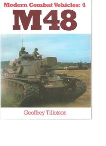

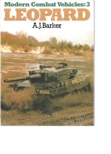


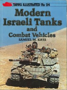
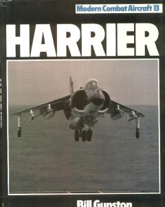
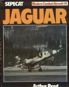


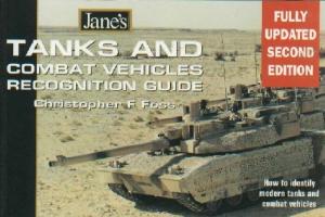

![[Profile Publications][AFV Profile 042] Modern Swedish Light Armoured Vehicles](https://docer.tips/img/300x300/profile-publicationsafv-profile-042-modern-swedish_5a98f562d64ab2fd07afd899.jpg)


![Modern Battle Tanks and Support Vehicles [Greenhill - Military Manuals]](https://docer.tips/img/300x300/modern-battle-tanks-and-support-vehicles-greenhill_5a567c2cd64ab23575e2dd60.jpg)


![[Motorbuch Verlag] - Soviet Tanks and Combat Vehicles of WWII](https://docer.tips/img/300x300/motorbuch-verlag-soviet-tanks-and-combat-vehicles-_5a562e3bd64ab2c2de951013.jpg)
![[Panzer Tracts 14] Gepanzert Pionier-Fahrzeuge - Combat Engineer Vehicles](https://docer.tips/img/300x300/panzer-tracts-14-gepanzert-pionier-fahrzeuge-comba_5a9554e3d64ab27c630afba7.jpg)