SERES 38 JERIES THIRTY EIGHT INf:AN-TR'f1rAt41CMARK m'VALENTINE' - (PART 2) 50p (UK) (UK) ABOVE: The second three man turret Valentine produced whilst...
127 downloads
93 Views
7MB Size
SERES
38
JERIES THIRTY EIGHT
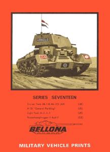
INf:AN-TR'f1rAt41CMARK m 'VALENTINE' - (PART 2) (UK) (UK)
50p
ABOVE: The second three man turret Valentine produced whilst undergoing trials, showing the extended turret front. The 30 gal Auxiliary Fuel Tank which nearly doubled the range could be jettisoned from inside the tank when going into action.
BELLONA MILITARY VEHICLE PRINTS - Series Editor: Hilary Louis Ooyle.
INFANTRY TANK MARK III VALENTINE - Part 2
VALENTINE MK. DI and MK. V - 2 pdr.
VALENTINE MK. VIII and MK. IX - 6 pdr.
Drawings and historical research by D.P. Dyer.
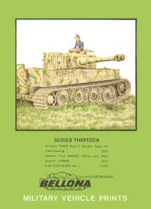
BELLONA PRINTS WHICH SHOULD BE STUDIED IN CONJUNCTION WITH THIS SERIES: SERIES 34- VALENTINE I, II, IV, AND VII, SERIES 31 - BISHOP, SERIES 18 - ARCHER
INFANTRY TANK MK. DI VALENTINE MK. ID/V In order to overcome the disadvantages of the two man turret as fitted to the earlier marks of Valentine a three man turret was introduced. A simple expedient was used to give more room within the confines of the small diameter turret ring. This was to move the trunnions for the 2 pdr. gun forward by 8" and the rear of the turret backwards by a similar amount forming an overhang . The gun was still fitted with an internal mantlet, but the turret front was of a different design. By using the space formed within the turret overhang to contain the wireless set, sufficient room was made behind the 2 pdr. for a seat for the commander. Above his head was located a circular rotating hatch fitted with a periscope . The hatch cover insisted of three separate hinged sections so that the commander could use his periscope without having to close up the hatch completely. This hatch was the only means of entry into and exit from the turret for the three turret crew members. 2
i
Because of the additional weight of the elongated turret and extra crew member the thickness of armour along both sides of the hull was reduced from SO mm to 50 mm. This saved approximately 8 cwt so that although the new turret weighed considerably more than the original the total weight increase of the vehicle was kept down to Yo ton. According to Vickers Limited, the design of a three man turret for the Valentine tank was instigated in November 1937 and entered production in 1939. If this is the case it is difficult to see why the design for a two man turret with 2 pdr. gun was ever put into production. Despite strenuous efforts by the author to either view or obtain copies of supporting documents to ascertain the true facts, the matter is still unresolved along with various other problems. It could be that the three man turret was part of the original design but was shelved due to the gun projecting in front of the vehicle. Whilst, in the light of later developments, this may seem ridiculous it must be remembered that before the War no Country had produced tanks with guns that projected ahead of the vehicle. This was in case a long gun barrel would be damaged when the tank was operating amongst trees. In the United States the 37 mm gun fitted to the Light Tank M2A4 was shortened by six inches for this very reason. The earliest three man turret Valentine so far identified is T.S6591 which was received at the Mechanical Warfare Experimental Establishment from Vickers Armstrong Chertsey on 13th April 1942. Stowage diagrams are dated for 13th July of the same year, all of which tends to help date this mark as only being produced from early 1942. There were two versions of the three man turret Valentines, the MK.III which was fitted with the A.E.C. Diesel engine, and the MK. V which had the alternative G.M.C. Diesel engine. Both of these marks were externally identical. The hull itself was the same as the MK. II/IV with two long stowage boxes on the right hand track guard and spare track links carried on the left hand front track guard. Auxiliary 30 gallon fuel tanks were standard, as were five P.O.W. cans carried at the rear. Valentines with three man turrets fought in the North African campaign along with MK.II/IV as well as in various other theatres of operations. Out of the 2 pdr. armed versions of the Valentine, the three man turret models were the ones selected for conversion to Duplex Drive Swimming Tanks. The majority of these DO tanks however, were eventually only used for training purposes. BELOW: An aerial view of the same vehicle illustrated opposite showing details of the turret top. The Commander's sighting vanes are folded down in front of the ventilation slot.
3
> ~
m
~>
on
~
~
w
Z
t-
Q
Z
a:
.....I
a;
W
<{
UJ
b c;
> '"> Z
~
~
~ ~
Z o
~
<{
t
> 0=:: t-
Z
<{
"
Z
4
•
a: a
(II
1: 35
LAKEMAN AA
MOUNT
VALENTINE V
GUN
40mm
Ll52
OUICK FIRING
© Feb '7 4
~.
CALIBRE
2pdr ORDNANCE
BREN'303 MACHINE GUN (adapted for drum magazine)
SCALE
BOX 16 BREN MAGAZINES)
GEARBOX SPICER (MEADOWS ON Mk "I )
/ ' " 'IAE<:: ' ' ' GMC 2 ST'''' DIES" 4 STROKE DIESEL ON Mk Iii)
STOWAGE
SECTIO N
1D
~-.:~ 0
:0
5
0
-
t
- ::: - I I
I
I
i
2
I 3
15 FEET
I
I 4
IN FAN TRY TA NK Mk.l ll ,
6
•
I M E TRES
VALENTINE Mks III & V
7
co
.t
( lOA
..w~. /"
H S I
I LI
\""-. ~
D~ !
....... ,~_SA}"!!!!!"Ir!:'
-.-.
u......... .
. - ]I
2 WATER BOTTLES
BESA A ND BAG
DEFLECTOR
NOTE: BOX, FIRST A ID OUTFIT, & EXTINGUISHER, FIRE CARRIED IN FRONT L.H. CORNER.
':'~ ."! '
• - --
7
i BAG, 2 PDR_ SPENT .:/ CARTRIDGE CASES
.~CARTRIDGE'CASE
DO
i ~
~j
L
LAMP, HAND, HELLESEN SATCHEL. SIGNAL
12 CARTRIDGES SIGNAL
-- . ,.-
C I!il' ....
_
~Sn
""J
VALENTINE III & V STOWAGE SKETCH-INTER IOR-TURRET & HULL, N.S.
<
PISTOL. SIGNAL
.' •
I
(
I!{~ !.
-r
«
4 BOMBS SMOKE, 2-11''1
HAVE RSACK __
1- 2PDRRD.
CASE, MAP G.S. II:': __ iJ: .
6GREN HAND
~_:"a-c
CD
>
co::
NOTE:
RECOGN ITI ON SIGNALS
STOWED WHERE CONVEN IENT
COMPRESSOR JUN IOR NO,2
BOX BESA 7,92 MM, AMM N,
'
'>
CLEANER, BR IST LE, IN CAPSp·ONGE, R, H, F, OF HULL
BOX BESA 7,92 MM, AMMN , IN FEED TRAY,
CAN, 0 1L , M,G, CAN GREASE M,G, &
PL UGS, CLEAR ING
BESA M,G,
PER ISCOPE TANK
3 T INS O INTMENT, ANTI-GAS
\'
•- - -
fJII\"
Wil . . .
ii::,~ .
~
ROD, CL EAN ING, M,G,
BREN M,G _
WIRE L ESS SET, NO,19
LPACK, SPARE PARTS AND TOOLS BESA M,G,
53 CARTR IDGES Q,F, 2 PDR"
BOX BESA 7,92 MM, AMMN , F LAGS, D I ST INGU ISHI NG BOX BESA 7.92 MM, AMMN. ~_ _ _ _ _
""\t. .
i.
-Q'
I¥1hlLIF iiJEilii}\1J
9
8CARTR IDGESQ,F_2PDR ,
B~~!\~~~~~:MMN, BOXES
~.llIlf i~m
~,
W'
C L EANING, 2-~N BOMB THROWER
J-flIl-lt'-----:-'-'-..- - - - - - 7 BOMBS, SMOKE, 2-IN,
~~-D!_~~~-- BRUSH,
!;:;::~:I'fi'~:;-':"----"7-'---,------ 80MB- T H ROWE R, 2- 1N,
bJl]d~ji!~~::=-:---_ 7 BOMBS, SMO KE, 2- 1N,
VALENTINE III & V
STOWAGE SKETCH -INTERIOR TURRET & HULL.O.S.
/~ w~ ~
't,
F
_ C -e:::it;;;s... . . if~-~:== PE R ISCOP E, TAN K
ABOVE: Frontal view of MK. III or V showing the configuration of the new turret front The 2" smoke bomb thrower aperture can be seen to the left of the Besa machine gun. (RAC Tank Museum)
BE LOW: Right hand side of the MK. III or V, the subject of all four photos in this booklet. As with the photo above the Bren gun adapted to fire drums of ammunition is fitted to the Lakeman A.A. mount but held in the ever readv travelling clips. (RAC Tank Museum)
10
2pdr AP
~ 75mmAPC
LOADER/W IRELESS
OP ERATOR
~"" *·,$W·p@
~lQSV
)~
2 pdr
TUR RET PLATFORMS
ROUND
OMMANDER
GUNNER / WIRELESS
GUNNER WIRELESS
59 ROUNDS 2 pdr (40mm)
COMMANDER LOADER
OPERATOR
53 ROUNDS 6pdr. (57mm)
COMMANDER/LOADER
Mk. I, II, IV, VI, VII
'-1Y'r\~
¥1' , "' VJ:f~J ,I
~vr51 ROUNDS 2pdr (40mm)
Mk.lIl. V
5pdrAPC
~ n
AMMUNITION COMPARISON
Mk. VIII, IX,
ABOVE: % front view of T67111 a standard MK. VIII or IX fitted with a 6 pdr. MK. III gun showing
the bulge on the mantlet above the gun to protect the recoil cylinder. (RA C Tank Museum)
INFANTRY TANK MK. III VALENTINE MK. VID/1X Wth the pressure to obtain tanks armed with the new 6 pdr. anti-tank gun as requested by the War Office in November 1940 the Valentine was not even considered for upgunning. At first the Cromwell tank was intended to mount the new gun, but as it was realised that a long time would pass before this would be available. Because of this delay the Crusader and then later the Infantry MK.IV Churchill were scheduled for upgunning in March and April 1941 respectively. It was not until August 1941 that the design for a 6 pdr. turret for the Valentine was started. In view of no official instruction having been located to date, it is now presumed that this was a design undertaken by Vickers Armstrong on their own initiative. This task was probably initiated via the 'old boy' network in view of the debacle whi ch had occurred with the Crusader and Churchill turret developments . In order to fit a 6 pdr. within the confines of the Valentine turret the fourth crew member had to be
dispensed with again and the turret redesigned for the second time. Because of the size of the recoil
cylinder of the 6 pdr. a narrow external mantlet to protect this was de si gned, and the front turret casting
reshaped to accept this giving a pointed form. The sides and rear of the turret remained similar to the
previous three man turret, but the roof plates were altered to give each of the two remaining turret crew
members an entry hatch. This was necessary not for ease of access but in view of them being completely
separated from each other by the recoil guard of the larger 6 pdr. gun. A s the repositioned commander
did not have a rotating hatch he was provided with two periscopes to enable him to look backwards as
well as forwards, and a periscope for the gunner was re-introduced. In an effort to disperse the fumes
of the larger gun, a ventilator fan was installed in the roof of the turret.
In a further drive to save space the co-axial BESA machine gun was eliminated along with the 2" internally loaded bomb thrower. This bomb thrower had been developed to fire through the front plate of all pre ceeding models.of the Valentine. In order to give the 6 pdr. armed Valentines the capability to lay down smoke, two four inch smoke bomb throwers were now installed outside the turret on the right hand side. These were fired by electrical means from inaide the turret. To save the weight 'of the Valentine increasing to an unacceptable level when fitted with the 6 pdr. gun, and its more weighty ammunition, the side armour of the vehicles was once again reduced. Thus the 60 mm of the original versions became 50 mm for the three man turret versions and finally 43 mm saving an estimated 5cwt on the Valentines with 6 pdr . armament. According to Vickers Limited the 6 pdr . turret for the Valentine entered production in December 1941. If this claim is correct the Valentine may have been the earliest 6 pdr . armed tank and not tht;! Churchill which is frequently claimed as such.
12
Two versions of the 6 pdr. armed Valentine, without a co-axial machine gun, were produced, again due to the type of engine fitted . Those with the A.E.C. Diesel being designated MK.VIII, and those with the G.M.C. diesel MK. IX. Because of the increasing weight of the tank with its heavier turret, heavier gun, and heavier ammunition, the power to weight ratio had gradually decreased. To improve the performance it was found possible to uprate the G.M.C. diesel to 165 bhp and these more powerful engines were fitted to the last 300 MK.IX without any change in designation . The earliest 6 pdr. guns fitted to tanks were the 6 pdr. MK.lII. The barrels of these guns appeared short and fat and were similar to the 6 pdr. MK.lI, towed. Firing Ap·T (Armour piercing shot with tracer) they had a muzzle velocity of 2,700 fps. In order to improve the armour piercing,capability of the 6 pdr. to the maximum the barrel length was increased to 52 calibres which in turn increased the muzzle velocity to 2,950 fps. The designation for the new gun becoming the 6 pdr. MK.lV,towed, and the MK.V 6 pdr . for tank use. Whilst the guns mounted on field carriages were fitted with muzzle brakes, these were never fitted to tank guns; tank guns having simple threaded muzzles which were fitted with counterweights. A capped shot for use against face hardened armour was introduced in October 1942 (APC -T) followed by armour piercing capped balistic capped shot (APCBC-T) in January 1943, a compo site rigid shot (APCR-T) in October 1943, and finally Discarding Sabot shot (APDS) at the end of the same year . All of these projectiles improved the performance of the already very efficient weapon. Firing APCBC shot the 6 pdr. was comparable to the German 7 .5 cm KwK . 40 L/48 as fitted to late models of the Pz. Kpfw rv and Stu. 9.I1I and made the Valentine equal to these in terms of fire power at least. Some of these Valentines were also exported to Russia under Lend-Lease arrangements where they fought along side the T-34.
BELOW: Frontal view of MK. VIlI or IX. T67111. This vehicle was part of a contract placed with Vickers Armstrong in May 1941. The bracket projecting to the left of the turret was for the 4" smoke bomb throwers fitted as from these models. (RAG Tank Museum)
13
x 06
-
:>
g,
11\ ~
~ LI.J
Z f-
Z
Q
LI.J .....I
>
a:
w
i5 a:
ci
> en z
~
..:,t.
~ ~
Z
>
~
0:: f-
Z
N
'"
"0
"
'"
14
a: a
-' U1
ELEVATION
HANDWHEEL
OPENING
VALENTINE IX
VENTILATION Mk 11\ GUN IOlternollve 6pdr MkV)
1:35
DRIVERS COMPASS
6pdr
SCALE
"'- ~- --=<\
ENGINE
2 STROKE
DIESEL ON Mk Xl
OIESEL
IMEADOWS ON Mk X)
IAEC 4 STROKE
GMC
SECTION
~',
6 pdr. Mk.V
L/S2
6pdr.Mk.111 L/4S
o
o
~- oF- - : ~ NFA N T RY
16
15 FEET
:0
I I
3
4
TANK Mk.lll,
METRES
.
VALENTINE
- ,- - .',
Mks V III & IX
17
C!O
...
THOMPSON SUB/M.G.
-==-'""
u
'"
•
~
VALENTINE IX
STOWAGE SKETCH-INTER IOR- TURRET & HULL, N.S.
"
/4
9-6PDR. RDS. ____________________________- 4
6-6PDR.RDS.
7·6 PDR. RDS.
e
. .... ..
/
,~~-=-
~
< "1111111111-
)~
'~~" :'
,~
2BOTTLES.WATER _ _ _ _ _ _ _ _ _ _ _~
FLAGS, DISTINGUISHING (1 SET)
3· 6 PDR. RDS.
BREN M.G.
& COVER MUZZLE
WIRELESS SET. NO. 19
41-'RISMS (SPARE) FOR TANK PERISCOPt::--- BRUSH CLEANING PERISCOPE----:-""""~:=--~ PERISCOPE, TANK--~!!!! 8 THOMPSON SUB/M.G. 20 RD. MAGAZINES BINOCULARS j1rS!! CASE, MAP G . S . ·" SIGHTING TELESCOPE . w - , '." LAMP HAND HELLESEN If '.''': .., . .y, f .1 2 TINS OINTMENT ANTI ·GAS . ·:·,.·(" W Cit. I I: , .~ '.. ' at> J. • WALLET , B R E N . , ; . ~ .. .~~
BOX. FIRST AID OUTFIT & EXTINGUISHER. FIRE CARRIED IN FRONT L.H. CORNER .
-0
CD
" "~
4 GENERATORS, & 4 COVERS, DISCHARGEf, ,
, c~ ,
~ SE~§HEET3
CARTRIDGE, SIG
~.
: ~ :;;§Jtt"
,
' .
'"
.
g=.~ ,
:
,
-:==:=0
(~
SCRAP VIEW OF R.H. FRONT OF TURNTABLE.
& 2 PROTECTORS. OBJECT GLASS:
",
,
.
'
it~
CAN, OIL, " WESCO",, WITH FLEXIBLE SPOUT BOX, SPI>:RES AND TOOLS, :
2PDR'ANDMTG{FOR6POR~
--"'-SEESHEET3.
~~
SA TCHE L, SIGNA L DISCHARGER, LEVERS & CABLES / -\ ENADES. HAND--""/ { \ :,.303 RIFLE • ...:, ~ ~ , ~'~
VALENTINE IX
STOWAGE SKETCH-INTERIOR-TURRET & HULL. O.s.
"
PERISCOPE TANK 3 GRENADES HAND .303 R IF LE
...,.SEE SHEET 3
CANYARD,COCKING BAG6PDR BOX, CARTRIDGE , 303 RIFLE , GRENADE SPENT CARTRIDG'E
"
- ~ir'
~ ~ ~", .
_ I lIi i'4.
~ <=
Technical Specification for Tank lnfantry M K.I1I, Valentine M K. III, V, VIII, & IX. Where different to MKS. I, II, IV, & Vi.I , or where not quoted previously.
Crew: MK.I1I & V Weight, combat loaded: G round pressure : Power to weight ratio :
4 - Driver, Commander, Loader, Gunner Mk.I 15% Tons Mk.1I 16% Tons Mk. III & V 16% Ton s Mk.VIlI & IX 17 .2 Tons Mk.l1I & V 1 0.51bs sq .inch Mk.VII & IX 11 .28Ibs.sq . inch Mk.III & V 7 .7 ton s per HP Mk.VIII & IX 7 .56 tons per HP Mk. IX last 3009 .6 tons per HP
Dimensions Length over gun:
Mk.l1I & V 18' 3" Mk .VIII & IX 20' 9" Mk. V 6 pdr . Mk. VIII & IX 19' 5" Mk. III 6 pdr. Mk. I, II & IV 6' 11" Height over Mk. III & V 7' 4" periscope: Mk. VIII & IX 7' %" Mk. III & V AEC A 190 Engine: 6 cylinder four stroke diesel 130 hp water cooled Mk . VIII & IX GMC 6-71 Model 6004 6 cylinder two stroke diesel 130 hp water cooled Mk . IX la st 300 as above but 165 hp Mk . III & VIll Meadows Transmission: type 22 clash 5F 1 R Mk. V & IX Spicer synchrome sh 5F 1 R clash top and reverse Sighting & Vision : Mk . III & V 1 telescopic sight 4 ta nk peri scopes 2 pi stOl port s Driver's Dire ct vi sion port Mk. VIII & IX 1 telescopic sight 3 x No.6 peri scopes 2 x NO .3 peri scopes 2 pi stol port s Driver's direct vision port
Armament:
Ammunition Stowage:
Fuel capacity :
Armour :
Armour thickness:
Mk. III & V 1·2 pdr. OQF 4.9 mm k/52 Elevation +20 - 15 1·7.92 mm Besa MG co·axial 1,.303 Bren MG AA Mk . VIII & IX 1·6 pdr . OQF 57 mm L/45 or Lj52 Elevation +17 _ 8 ° 1 .303 Bren Mg AA Mk. I, II, IV. 2 pdr . 60 rds . 7 .92 mm 3150 rds . (14x225 rds boxes) .303600 rds (3 x 200 rds boxes) outside turret Mk . Ill , V 2 pdr. 62 rds. 7 .92 mm 3150 rds .303600 rds (box outside turret) Mk. VIII & IX 6 pdr. 53 rds. .303600 rds. Mk. I 56Y, gals petrol All other marks 36 gals All marks could be fitted with .30 gal . auxiliary fuel tanks externally Turret Cast homogenous front, mantlet, and rear rolled plate sides and top. Cast turret in· troduced canadian veh icles Hull Rolled Plate Cast front in· treduced Canadian vehicles Construction Early models bolted and rivetted, welding introduced later model s. Side Mk.III, Mk. V -50mm Mk.VlII, Mk.IX- 43mm
Published by MODEL & ALLIED PUBLICA TlONS LTD. P. O. Box 35, Hemel Hempstead, Herts. HP 1 1EE
Copyright 1974. Model & Allied Publications Ltd. and D.P. Dyer.
Printed in England by
Technical Print Services Limited,Brentcliffe Avenue, Carlton Road, Nottingham.