I The Illustrated Encyclopedia of 20th Century The Illustrated Encyclopedia of 20th Century EAPONSAND ARFARE VOLUME 21 RPG/Skyraid The Illustrated Enc...
151 downloads
188 Views
29MB Size
I
The
Illustrated
Encyclopedia of 20th Century
The
Illustrated
Encyclopedia of 20th Cent ury
EAPONS ARFARE AND
,
VOLUME 21 RPG/Skyraid
The
Illustrated
Encyclopedia of 20th Century
EAPONS """arfare
ICOLUMBIA HOUSE/New York
Editor: Bernard Fitzsimons
Gunston (Aviation) Hogg (Land Weapons) Antony Preston (Naval) Deputy Editor: Su/anne Walker CJopy Editor: Michael Maddison Consultant Editors:
Bill
Ian V.
Assistant Editors: Will Fowler, Richard Green,
Corinne Benicka, John Liebmann, Michael de Luca Editorial Assistant: Julie Leitch
Art Editor: David Harper Assistant Art Editor:
John Bickerton Design Assistants: Jeff Gurney, John Voce Production: Sheila Biddlecombe Picture Research: Jonathan Moore David Brown, Norman Friedman, Ian Friel, Contributors: Michael J. Gething, Bill Gunston, Mark Hewish, Ian V. Hogg, John Jordan, David Lyon, Pamela D. Matthews, Kenneth Munson, Malcolm Passingham, Antony Preston, John A. Roberts, C. J. Ware, Anthony J. Watts, John S. Weeks, M. R. Wilson Illustrator:
John Batchelor
Cover Design: Harry W. Fass Production Manager: Stephen Charkow
© Purnell & Sons Ltd.
1967/1969
©Phoebtis Publishing Company/ BPC Publishing I.td. 1971/77/78 Distributed bv Columbia House, a Division of CBS Inc., 121 .Avenue of the .Americas. Prinrrd in the U.S.A. 1
New
Vork,
New
York 10036
"War
is
cruel
and you cannot refine it." —William Tecumseh Sherman
INTRODUCTION The Illustrated Encyclopedia of 20th Century Weapons and Warfare features, among the usual variety of modern military hardware, a number of the products of the Volume
21 of
More conventional
ume
aircraft featured in Vol-
of course, one of the pioneers of aviation, hav-
Lockheed F-80 Shooting United States and one of the USAF's first jet fighters; the North American F-86 Sabre, first American supersonic fighter and hero of the first large-scale jet-against-jet combat over Korea;
ing produced the world's
the Douglas A-1 Skyraider,
Sikorsky company, one of the world's leading
producers of helicopters. Igor Sikorsky was,
airplane in 1913 and the
ometz
strategic
bomber
first
four-engined
enormous
Ilya
Mour-
in the following year.
After his emigration to the United States he
was
also responsible for the
Pan American
Clippers, pioneer flying boats of the 1930s. His first
21 include the
Star, the
second
jet aircraft to fly in the
aircraft pro-
first
meet the US Navy's new attack role duced after the Second World War, and the McDonnell Douglas A-4 Skyraider, one of the most successful of all combat aircraft and still in to
production after nearly 30 years.
military helicopter to be built in quantity
was the R-5; the second was the S-55, which remained in production for more than ten years
and was built under license in Britain, Japan, and France. After the S-55 came the S-56, originally an assault transport for the US Marines, and numerous other designs, of which the best-known
is
probably the S-61 Sea King,
Land warfare
is
represented in the form of the
M4
Sherman, one of the most widely used tanks of the Second World War— and after— of which almost 50,000 were built. A more recent family of fighting vehicles
Scorpion
series,
is
which includes the
the British light tank.
Scimitar armored reconnaissance vehicle and
used in numerous military roles since 1961.
Striker guided-missile launcher, as well
The
APC, command
Sea King served in a
number of countries
and was built under license by Agusta in Italy, Westland in Britain, Mitsubishi in Japan, and the United Aircraft corporation of Canada. Remotely piloted
vehicles,
or
RPVs, have
often used rotary wings to provide
have led
to
such programs
as the
DASH
unmanned antisubmarine helicopter being abandoned. Simpler remotely controlled aircraft, however, have found a number of military applications, particularly in roles
the risk of casualty tion for
is
high.
ambulance and armored recovery vehicles all built on the same basic hull and suspension, and planned from the
where
One obvious
func-
which they are eminently suited
family— in contrast to the usual procedure which sees specialized conversions imstart as a
provised as the need
arises.
is
Volume 2rs coverage ranges from the Schnellboote— better known as "EBoats"— of the Second World War and the Finally, at sea.
Soviet "Shershen" class fast patrol boats of the
1960s to the
The Scharnhorst, one of the capital which posed a constant threat to Allied shipping during the war, actually achieved very
stricted
enemy
missiles; others include battlefield or photo-
graphic reconnaissance, pathfinding and elec-
battlecruiser Scharn-
ships
ward
target practice or as decoys for
German
horst.
acting as aerial targets, either for straightfor-
tronic countermeasures.
post,
lift,
the peculiar control problems of this flight
though means of
as
little
because their movements were
by fear of their
loss.
re-
RPG
RPG recoilless
Soviet
weapons.
antitank
The Soviet RPG-7, derived from the RPG-2, fires a bigger projectile up to 500 m (550 yards) and unlike many AT weapons
The
RPG-2, which appeared in the mid-1950s, was little more than an improved version of the German Panzerfaust. It consisted of a short tube containing a propellant charge, with a pistol grip and sight. The projectile
was
bomb
with base fuze and had a diameter substantially greater than that of the launcher tube. It carried a tail boom fitted with four flexible sheet-metal fins which wrapped around a reduced-diameter a hollow-charge
section of the boom. The complete tail unit was loaded into the front end of the launch tube, and launched by pressing the trigger. The propellant charge fired the bomb forward, and eliminated recoil by discharging a stream of gas through the rear end of the
As
tube.
the
bomb
left
the
it
can be used
enclosed areas
targets to help develop an efficient rangefinder for British coastal-artillery batteries.
RPV Remotely
in fairly
piloted
vehicles.
The
casual
The
tests
were called Low and
off
on the verge of team went on to
pbserver could be forgiven for supposing that
success, but
RPVs
develop a flying-bomb type of RPV for the Royal Flying Corps. This was technically successful, though it was never employed experiments with operationally. Similar 'aerial torpedoes' were later undertaken in the United States, sponsored by the Army and Navy. Low's device was given the cover
are a relatively new arrival on the aviation scene. Nothing could be further from the truth, for the first known attempts at controlling an aircraft by radio or other means of remote control were made in 1914, soon after the outbreak of the First World War and barely ten years after the Wright brothers' first successful powered flight.
These experiments, by Professor were intended to use pilotless
A
M
Low,
aircraft
as
his
designation A T (aerial target) to disguise its true purpose. After the war development work was
tube the fins
sprang out and stabilized its flight. With an range of 150 m (165 yards), the bomb could penetrate about 175 (7 in) of armour. While basically of the same configuration effective
The Canadair CL-227 RPV, a
free-flying rotorcraft
over areas for sustained surveillance, unlike winged
which has the advantage that it can hover RPVs which can only pass over the target
mm
as the 1962,
RPG-2, the RPG-7, which appeared in an entirely new design. It has a good
is
optical rangefinding sight fitted as standard,
CANADAIH CL-227
but this can be replaced by an imageintensifying sight for night operation. The projectile has a new fin system and a rocket motor incorporated inside the tail boom. The warhead is slightly larger than that of the RPG-2 and incorporates a piezo-electric impact fuze with self-destruction device. The jack-knife fins lie alongside the tail boom when inside the launch tube and spring out and back as the bomb is fired. A small propellant charge in the tube serves merely to throw the bomb clear of the tube, and after about 10 (33 ft) of flight the rocket motor ignites and accelerates the rocket to the target. This system of propulsion causes the rocket to pursue a complex trajectory after launch, dipping and then accelerating away, but this is compensated for in the design of the sight, which gives very good accuracy. The effective range is 500 (550 yards). The RPG-7 is widely used by Soviet allies
m
m
and
combination of size, target and accuracy make it one of the most
guerrillas. Its
effect
formidable weapons of
its class.
Launcher calibre: 40 mm (1.57 in) Warhead diameter: 80 mm (3.15 in) Projectile weight :^.6A kg (4 lb 1 oz) Launcher weight:2.63 kg (6 lb 4 oz) Launcher length: 1 19.4 cm (47 in) (RPG-2)
Effective range: 150
m
(165 yards) Velocity: not
known (RPG-7) Launcher calibre: 40 mm Warhead diameter: 85 (3.35 in) Projectile weight:2.25 kg (4 lb 15 oz) Launcher weight:? kg (15 lb 7 oz)
mm
Launcher length: 990 mm (39 in) Effective range: 500 m (550 yards) Velocity: 300 m/sec (984 ft/sec)
RPK Soviet machine-gun
See Kalashnikov
2241
RPV aimed
at
producing pilotless target
aircraft.
Typical of such vehicles during the 1920s were the Royal Aircraft Establishment (RAE) 1921 Target (of that year) and the Sperry Messenger in the US. The RAE had encouraging successes with its Larynx pilotless aircraft, which was tested in the desert in Iraq carrying a live warhead, but this was the RAE's last aircraft design. Further radiocontrolled aircraft development in Britain then centred chiefly upon adaptations of existing piloted aircraft such as the de Havilland Queen Bee, which was based on the Tiger Moth and used exclusively for target practice.
The next major advance was made in Hollywood by an actor and model-aircraft enthusiast named Reginald Denny. He believed that radio-controlled scale models could provide realistic artillery targets at a fraction of the cost of full-size machines. After successfully testing his 2.7-m (9-ft) span RP-1 prototype in 1935, he formed the
o ~
Two MQM-74C Chukar
11 target
drones bearing the names 'Iron Butterfly' and 'Psychotic US Navy and civilian team during an exercise in 1976
Reaction' are prepared for launch by a
Radioplane company (now the Ventura Division of Northrop Corporation) to develop his ideas further. Radioplane received a small experimental order from the US Army Air Corps for the RP-4 model of 1939, but the real harvest was not reaped until after the US entered the Second World War, when thousands of targets were suddenly needed: Radioplane, together with other US companies like Culver, Frankfort and Interstate, could hardly turn them out fast enough. Inevitably the flying-bomb concept reappeared during the Second World War, leading to explosive-laden pilotless aircraft such as the Interstate
TDR-1, numerous RPVs by
Globe, Temco, Fairchild and McDonnell, and the much larger remotely piloted bombers packed with explosives such as the BG-7 (Aphrodite) Fortress and the AAF/Navy conversions of the Liberator, whose pilots usurode in an accompanying B-34 or PV-1
ally
Ventura.
The US Navy's Bat and the German Henschel Hs 293 and the notorious FZG or V-1 were not, in the strictest sense, remotely guided vehicles. The term 'remote piloting' should be reserved for a vehicle whose behaviour throughout its mission is under the guidance of a remotely based controller on the ground or in a director aircraft. Apart from being cheaper to mass-produce than full-scale manned aircraft, RPVs have the attraction that they can be employed for hazardous missions without placing a pilot's life at risk. An RPV equipped with photographic, infrared or TV cameras, or a search radar, and a data link or relay, can be guided to its target by a remote controller and feed back telemetered data. If goes well it can then be flown back, all recovered, and re-equipped for another mission. Equipped with underwing weapons it becomes a miniature strike aircraft; with electronic jammers it can put an enemy radar out of action or act as a decoy; with a laser rangefinder and target designator it can act as pathfinder for a following strike force of
armed RPVs or manned
An NV-130 Nutcracker in
1976.
2242
TEDS
is
Tactical Expendable
intended to be an
Drone System (TEDS) during trials b> the USAF which would penetrate enemy radar cover
ECM RPV
aircraft.
Equipped
with a small warhead, an expendable RPV can be sent in to silence an enemy radar or knock out a tank. The first major operational use of RPVs was in the early 1970s, in the US intervention in Vietnam, although reconnaissance RPVs
3
R.S.14, Fiat
Epervier (swallow), a Belgian army battlefield surveillance RPV, lifts off from its truck launcher during field trials. Tlie modest cost of to research and development by many nations. RPVs can be used for a wide range of tasks with no risk to a crew
had previously been used over the Chinese and other borders. In Vietnam, photoreconnaissance RPVs played a major part in detecting troop movements and returning post-raid pictures, enabling accurate
damage
be made. The Israelis found RPVs useful in the October 1973 war, both for reconnaissance and for decoying Egypt's
assessments
SAM
(Canadair CL-227; Canada) Propeller/rotor diameter: 2.3 m (7 ft 6 in) approx Height: 1 .32 m (4 ft 4 in) Gross weight: 93 kg (205 lb) Maximum speed: 130 km/h (81 mph)
to
missiles.
The enthusiasm which grew up around the RPV in the mid-1970s now seems to have subsided, but a wide array of configurations remains. They include truck-mounted tethered rotocraft such as Dornier's Kiebitz
(Dernier
Do 34
Kiebitz;
West Germany) Rotor
diameter: 8 m (26 ft 3 in) Height: 1 .45 m (4 ft 9 in) Gross weight: 430 kg (947 lb) approx Maximum speed: not applicable (hovering platform)
(Lockheed XMQM-105 Aquila; US) Span: 3.76 m (12 ft 4 in) Length: 1 .83 m (6 ft) Gross weight:65 kg (143 lb) Maximum speed: 219 km/h (136
mph)
and Spahplattform and Kaman's shipboard
STAPL; CL-227
free-flying
and
rotorcraft
Westland's
(Canadair's
Wideye);
scale-
model-size mini-RPVs for battlefield surveil-
Lockheed's Aquila/Aequare and DSI's Sky Eye; twin-boom shapes like the ESystems E-45/55/100 series and NASA's hydrazine-engined atmosphere-sampling Mini-Sniffers; and 'midi' or 'maxi' size RPVs such as the Canadair CL-89, Meteor Mirach, Beechcraft TEDS (tactical expendable drone system) and Teledyne Ryan AQM/BGM-34
Epervier; Belgium) Span: 1.72 m (5 ft 8 Length: 2.38 m (7 ft 10 in) Gross weight: 142 kg (313 lb) Cruising speed: 500 km/h (311 mph)
(MBLE in)
lance, like
series.
(Teledyne Ryan BGM-34C; US) Span.- 4.41 m (14 ft 6 in) Length: 8.69 m (28 ft 6 in) Gross weight: 2720 kg (6000 lb) Cruising speed :760 km/h (472
mph)
R.S.14, Fiat reconnaissance seaplane. The first of this elegant and welldesigned AS A (Fiat) all-metal, twin-float cantilever monoplane, with twin Fiat A 74 RC38 840-hp radials, flew in May 1939. A Italian
RPVs has led
further 184 production machines were delivered between May 1941 and September 1943.
Designers Manlio Stiavelli and Lucio Lazzaachieved good performance figures with high top speed and a maximum range of 2500 km (1550 miles). Armament comprised a rini
machine-gun in a and two 7.7-mm (0.303-in) Breda-SAFAT weapons, each on a flexible mounting and firing through lateral
12.7-mm
(0.5-in)
Scotti
Lanciani
dorsal
turret
side of the fuselage. The carried in a long detachable ventral gondola in combinations of up to 400 kg (880 lb). The R.S. 14 carried a crew of four or five. It was July 1942 before the 83rd Gruppo, the first to convert, brought the R.S.14 into operational service, but once in service it
hatches
either
bombload was
performed very efficiently. It was used mainly in reconnaissance roles, and also in the bombing and air-sea rescue roles. At its peak the R.S.14 equipped nine Squadriglie. After September 1943 a number flew with the Italian cobelligerent air arm, and several survived into the postwar period. A single prototype of the A.S.14 land-based attack
bomber
was
derivative
built.
two prototypes of
(DSI Sky Eye l-B; US) Span: 3.5
Length: 1.7 (125
lb)
m
(5
ft
Maximum
m
(11
ft
6
in)
Gross weight: 56.7 kg speed: 222 km/h (138 mph) 7
in)
CM
Span.- 19.54
m
(64
ft 1
in)
Length:\4.^
m
(46
ft
Gross weight: 6470 kg (18673 lb) Maximum speed .390 km/h (242 mph) at 4000 m (1 3 000 ft)
in)
2243
RSC
»
A St
Etienne
and
in
1935
M1917 RSC semiautomatic rifle. It has a chequered was withdrawn and converted to bolt action
career
it
RSC
which would accept the 8-mm (0.315-in) Let)el cartridge. It was also known as the Fusil Mitrailleur Mle 1917, or St Etienne
(DE.581), M^r/V/Vr(DE.582), George A Johnson (DE.583), Charles J Kimmel (DE.584), Daniel A Joy (DE.585), Lough (DE.586), Thomas F Nickel (DE.5S7), Peiffer (DE.5SS), Tinsman (DE.589), De Long (DE.684), Coates (DE.685), Eugene E Elmore (DE.686), Holt (DE.706), Jobb (DE.707), Parle (DE.708), Bray (DE.709). DE. 226-229, 232-237, 281-283, 590-606, 674, 687-692 and 710-722 became high-speed transports
Rifle.
(APDs).
French semiautomatic rifle. TTiis rifle, the of which commemorate the design team of Ribeyrolle, Sutter and Chauchat, was the final design of a series which had begun in the early 1900s. It was far from satisfactory in 1916. but the French army accepted it for initials
service since
The
rifle
it
was
the only automatic design
was gas operated, using a
piston fed from a five-round
and it retained clip which was unique to this rifle. It was a cumbersome and ugly weapon, and whilst the mechanical system may have been sound enough, the detail design was poor and the manufacture generally second rate. In 1918 an attempt was made to improve it by shortening the barrel and adapting the magazine to use the standard five-round clip used with the bolt-action rifles, but this design was not completed until after the armistice and relatively few of this Mle 1918 and bolt
carrier,
appeared.
The 5-in guns carried necessitated the lowering of the funnel and bridge heights to reduce topweight. The large number of closerange guns mounted in these ships was part of a general trend in US vessels towards the end of the war, and a reflection of the demand for increased firepower in the Pacific theatre.
APD
conversions were likewise the The result of the exigencies of the Pacific war,
where they were needed
on each
davits
were
withdrawn and converted to hand operation by blanking off the gas port and removing the piston, thus turning them into a species of straight-pull bolt-action weapon. In this form they were issued to African troops in French Equatorial Africa, before being withdrawn. In 1935 the rifles
all
mm
(Mle 1917) Calibre.-B (0.315 in) Weight:5.25 kg (11 lb 9 oz) Length.^33.^ cm (52.4 in) Barrel length:796 (31.4 in) Magazine: 5-round clip
augment
to
the
supply of landing craft. The conversion involved installation of two landing-craft on construction
side of
of
the
decks for
ship,
162
and the
troops.
A
mainmast was also fitted to operate cargo booms. Most Rudderows served in the Pacific during the war and none were lost. Chaffee was scrapped in 1948; Riley became the Taiwan Tai Yuan in 1969; Holt became the South Korean Chung Nam in 1963. The remainder have been disposed of since the lattice
mid-1960s.
mm
Muzzle
velocity:
716 m/sec (2350
ft/sec)
Displacement: 1450 tons (standard), 1780 tons load) Length:93.3 m (306 ft) oa Seam.- 11.3 m (37 ft) Draught: 3 m (9 ft 9 in) Machinery: 2shaft General Electric turbo-electric, 12000 shp=24 knots Armament: 2 5-in (127-mm)/38cal (2x1); 10 40-mm (1.57-in) Bofors; 6 20-mm (0.79-in) Oerlikon; 1 Hedgehog A/S mortar; 8 depth-charge throwers Crew: 220 (full
mm
(Mle 1918) Calibre: 8 Weight: 4.79 kg (10 lb 9 oz) Length: 109.5 cm (43.1 in) Barrel length:
586
mm
Magazine: S-round 670 m/sec (2200 ft/sec)
(23.1 in)
velocity:
clip
Muzzle
Rudderow us
destroyer escort class, built 1943-45. TTiese were the last of the six types of DEs developed during the Second World War, and they were a 5-in (127-mm) gunned version of the turbo-electric Buckley type. The main changes were the addition of a twin 40-mm
Bofors
AA
mounting forward and the reduction of the height of the bridge and
(1.57-in)
funnel.
Construction of the Rudderow Class began in the last quarter of 1943, and 71 had been launched by the end of 1944. Orders were given for 268 but eventually only 81 were completed, the rest being cancelled before launch. Builders included Philadelphia navy yju-d, Charleston navy yard, Bethlehem (Hingham), Bethlehem (Quincy) and Defoe (Bay City, Michigan). Only 22 were completed as destroyer escorts: Rudderow (DE.224), Day (DE.225), Chaffee (DE.230), Hodges {DE. 23 \), Riley (DE. 579), Leslie L B Knox (DE.580), McNulty
2244
Rufe
Allied
codename
A6M2-N fighter floatplane
for
Mitsubishi
See
A6M
Rugglero dl Lauria Three Ruggiero di Lauria at Castellammare di Stabia, Francesco Morosini at Venice arsenal and Andrea Doria at Ansaldo, Italian battleship class built 1881-89.
ships
La
were
built,
Spezia.
Intended as a development of the Duilio Class they were in fact only slightly larger and hardly any better armed because of
and financial pressures. As a result they were virtually obsolescent before they were commissioned. TTieir careers were uneventful: at the end of the century the armament was increased and in 1900 they were active in the Mediterranean fleet, but in August 1909 Morosini and di Lauria were struck off the list. Andrea Doria was laid up political
1911 but in February 1915 was renamed as a floating battery for the defence of Brindisi. After the war she was used as an oil depot, and scrapped in 1929. in
GR. 104 and used
Displacement: 11000 tonnes (normal) Length: m (347 ft 6 in) oa eeam.-19.84 m (65 ft 1 in) Draught: 7.77 m (25 ft 6 in) Machinery: 2-shaft reciprocating steam, 10000 ihp= 17. 5 knots Protection: 450 mm (17.7 in) belt, 356 mm (14 in) turrets and bulkheads. 76 mm (3 in) deck Armament: (Andrea Doria in 1915) 4 17.2-in (437mm)/27-cal(2x2);2 6-in(152-mm)/32-cal(2x1); 4 4.7-in (120-mm)/32-cal (4x1); 10 6-pdr (57mm)/43-cal; 17 1-pdr (37-mm)/20-cal; 2 14-in (36-cm) torpedo tubes Crew: 507 105.9
Rumpler C German
bomber and reconnaissance prewar Rumpler design, the unarmed two-seat B.I, was widely used as a light
aircraft series.
A
reconnaissance aircraft and trainer early
in
World War. A two-bay biplane powered by a lOO-hp Mercedes D.I, it was given a 160-hp D.III and armed with a ringmounted Parabellum machine-gun in the rear cockpit to produce the C.I. This was built in large numbers by Rumpler and several subcontractors, both as the C.I and as the C.Ia the
First
with a 180-hp Argus As. III. Later models of the C.I and all subsequent Rumpler C types had a synchronized Spandau machine-gun on the port side of the forward fuselage in addition to the observer's Parabellum. The C.I and C.Ia were widely used on the Western Front during 1915-16 and thereafter in Palestine, Macedonia and Salonika, both for reconnaissance and communications and as light bombers carrying 100 kg (220 lb) of bombs. A few survived in front-line service until the beginning of 1918. Derived from the C.I were the C.II, with staggered and slightly swept wings, revised rudder undercarriage and control surfaces, and new powerplant of a 220-hp Benz Bz. IV, and the CIV, with the original rudder, rounded tailplane and a 260-hp Mercedes D.IVa engine. The limited numbers of C.IIIs produced saw only limited service in early 1917, but the CIV, with excellent performat altitude, was licence-built by Pfalz as well as being produced by Rumpler, and was
ance
widely employed on long-range photographic reconnaissance, as well as carrying out bombing raids with four 25-kg (55-lb) bombs. Further improvement in altitude performance was achieved with the fitting of a 240-hp Maybach Mb. IV in the otherwise almost identical C.VI and C.VII towards the end of 1917. The C.VII was a standard radioequipped high-altitude photographic machine, but the C.VI, known as the Rubild (Rumpler bild, or Rumpler photographic), was a specialized high-altitude photographic version with no forward-firing gun, a service ceiling of 7300 m (23950 ft) and the remark-
9
R-Z, Polikarpov
m
able speed of 160 km/h (99 mph) at 6000 (19700 ft), putting it almost completely
The Russian armoured cruiser Rurik was
beyond interception. (CIV) Span; 12.66 m (41 ft 6 in) Length: 6 A^ (27 ft 7 in) Gross weight: 1530 kg (3373 Maximum speed: 170 km/h (106 mph)
roughly equivalent to the German BliJcher She had four 254-mm (10-in) guns, eight 203-mm (8-in) and 20 120-mm (4.7-in) guns. At the beginning of the First
m lb)
World War she was stationed RIJR-5
US antisubmarine weapon
in
the Baltic
See Asroc
Rurlk Russian armoured cruiser built 1905-08. After the disastrous losses of the Russo-Japanese war, the Imperial Russian Navy began an extensive rebuilding programme, and as part of this it placed an order for building an armoured cruiser with Vickers Sons and Maxim of Barrow-in-Furness. She was launched as the Rurikin November 1906 and handed over to the Russians for trials in 1908. The hard lessons of the war had been learned, and thus Rurik carried much more armoured protection than her predecessors in the Russian navy. Another new feature was the introduction of an automatic system to reduce the amount of heel should one side of the ship be badly damaged. During trials the ship's engines produced 20675 ihp, and she exceeded her contract speed. In 1909 Rurik joined the Baltic fleet, which was com-
manded by Admiral Von Essen, who expressed himself entirely satisfied with her. When the First World War began, Rurik and the rest of the Baltic fleet were soon on active service. Early in September 1914 Rurik and other cruisers were able to push back the German forward line in the Baltic. In November was decided to fit out Rurik and six other cruisers as temporary minelayers, and in mid-December she was the flagship of a force which laid a big minefield in the Bay of Danzig. Two German minesweepers later suffered serious damage from these mines. Rurik continued to participate in these minelaying operations until mid-February 1915 when she ran aground near Faro lighthouse and took 2400 tons of water into her hull. She went in for repair, but by the summer she was back in service. On July 1-2, 1915, she was escorting a Russian flotilla, but they became separated in fog and by the time Rurik located them again they were engaged in a fight with a German convoy. She began to engage the German cruiser Roon, but a mistaken submarine alarm led her to break off the action, and the convoy escaped. On November 19, 1916, she hit a mine off Hogland and suffered severe damage. The general problems of disrupted supplies and lack of manpower ensured that once repaired she took little further part in the war, and in 1923 she was scrapped. i
R-Z, Polikarpov Soviet light bomber/reconnaissance aircraft. In 1935 Polikarpov produced an entirely redesigned version of the R-5 biplane. Designated R-Z, it was powered by an 820-hp 34N engine and featured a new triangularform fin and rudder, a radiator relocated between the rear undercarriage struts, a
M
straight trailing
edge
to the
upper wing (with-
mm
out any cut-out) and a glazed canopy for the crew. The pilot's canopy section was semienclosed after the style of the Italian Macchi 200 and Fiat G 50 fighters. When not working his machine-gun the observer was completely protected from the weather by a glazed sliding panel. The R-Z had increased fuel tankage and range. Defensive armament
(submerged, beam); 400 mines (wartime) Crew: 899
comprised one fixed synchronized PV-1 machine-gun, and a ShKas weapon on a new ring mounting for the observer. A load of eight 50-kg (110-lb) bombs could be carried under the wing.
Displacement: 15000 tons
(normal) Length: Draught:!. m (26 ft) Machinery: 2-shaft reciprocating steam, 19700 ihp=21 knots Protection: ^52 (6 in) belt, 76 (3 in) sides, 102 (4 in) bulkheads, 38-25 (1.5-1 in) decks, 203-178 (8-7 in) guns Armament: 4 10-in (254mm)/50-cai (2x2);8 8-in (203-mm)/50-cal (4x2); 20 4.7-in (i20-mm) QF (20x1); 14 3-pdr (47-mm) QF (14x1); 2 45-cm (17.7-in) torpedo tubes 149.4 m(490
ft)
Beam:22.S
m (75ft)
mm
mm mm
mm
MC
The R-Z was designed with spatted wheels, but the spats appear to have been largely discarded in service. It was in large-scale production at Zavod No 1, Moscow, about 1(X)0 being built during 1935-37. As well as being employed in the Far East, 62 were sent to the Republican government forces during the Spanish Civil War, where they gained a reputation for reliability and toughness. They flew in formation and the crossfire of their movable ShKas guns firing 1800 rds/min deterred most enemy fighters. They were used for low-level attacks on enemy troops and strongpoints, and most of their losses were to antiaircraft fire. Nevertheless the Natacha,
as
it
was
nicknamed
by
the
Spaniards, fought on through two bloody years and 36 of the original 62 survived the war to fall into Nationalist hands.
Span; 15.5 m (50 ft 10 in) Length: 9.7 m (31 ft 10 Gross weight: 3500 kg (7716 lb) Maximum speed: 290 km/h (180 mph)
in)
2245
S.I
repaired by the submarine's engineers, and days S. I arrived at Harwich, in tow of her prize, at a speed of four knots. After this fiasco negotiations began to transfer the class to the Italian navy, in the hope that they would have better luck with Fiat engines. S.2 was completed in May 19 15 and ran trials, but never joined a flotilla S.3 completed in^ September but never hoisted the White Ensign. All three were handed over to the Italians in September 1915 (the official date of transfer was October 25). TTiey retained their numbers, and were discarded after five
;
1919.
in
Displacement: 254/303 tonnes (surfaced/submerged) Length: 45.3 m (148 ft 6 in) oa Beam:
m
Draught: 2.9 m (9 ft 6 in) Machinery: 2-shaft diesel/electric, 650 bhp/400 shp=13/7 knots (surfaced/submerged) Armament: 2 45cm (17.7-in) torpedo tubes (bow), 4 torpedoes Crew: 26
4.3
(14
ft)
S.1 submarine class, built 1913-15. In an break the Vickers monopoly of submarine construction and to broaden the experience of British designers, the Admiralty took out licences to build foreign British
effort
to
The first of these, taken out was with the Fiat company in Italy,
in 1912,
Laurenti-designed
to
designs.
boats
similar
to build
the
Argonauta Class. As they were to be built by Scotts at Greenock they were known as the Scott-Laurenti design, and were designated the 'S' Class. Only three boats were ordered, 5. 1-3. S. 1 was ready by August 1914 but S.2 and S.3 were not completed until the summer of 1915. 5.
/
was unpopular from
the start because
of her novel design, and especially because of the unfamiliar Fiat diesels. On the night of June 21, 1915, while on patrol north of Heligoland she was forced to submerge, first by a Zeppelin, then by two seaplanes, and finally by trawlers and a destroyer. Under this strain her diesels broke down, and she was forced to remain on the surface, trying to repair them so that the batteries could be recharged. When she surfaced again the following night she was still unable to get either diesel working, but she managed to extricate herself from this dangerous predicament by boarding and capturing the German trawler Ost next morning. The prize crew of an officer and five seamen started to sail Ost back to Harwich with 5. / in tow, but her engines broke down too. They were eventually
S.I us submarine
class. TTiree basic prototypes
built for a type much larger than the previous 'O' and 'R' Class designs with a wider radius of action and higher sustained surface speed. S.l was to a Holland design while S.2 was to a Lake design; S.3 was a Bureau design, and the first submarine to be designed by the US Navy. A production series of 14 boats (S.4-17) was based on the S.3 design with a further four (S.48-S1) built to larger dimensions to provide extra bunkerage. Displacement of this class was some 200 tons greater than in the 'O' and 'R' Classes, with an increase in length of just over 13.4 m (44 ft) and in beam of nearly 1 .2 m (4 ft). A 800-hp increase in the power of the diesels gave an extra 1.5 knots surfaced. Bunkerage rose from 75 tons to 148 tons. In line with increased endurance the torpedo armament was increased in S. 10-13 and S. 48-51. The boats entered service in
were
using a Cox-Klemin XS-2 floatplane. The project was finally abandoned in 1927. S.l was subsequently loaned to the Royal Navy in April 1942 as P552, and was returned and scrapped in 1946. The Holland design (5. /) was developed into the S. 18 Class, but the Lake design {S.2) was abandoned. S.2 and 5.50 were scrapped in 1931, S.IO in 1936, and S.3 and S.6-9 in 1937. S.4 was
on December 17, 1927, S.5on September and S.51 on September 25, 1925. Those which remained at the start of the Second World War were mainly used in a training role during the war, and were scrapped about 1946-47. lost 1,
1920,
{S.1) Displacement: 854/1062 tons (surfaced/ submerged) Length: 66.8 m (219 ft 3 in) Beam: 6.3 m (20 ft 9 in) Draught: 4.9 m (16 ft) Machinery: 2-shait diesels/2 electric motors,
1
200/1 5(X)
hp= 14/11 knots (surfaced/submerged) Armament: 1 4-in (102-mm); 4 21-in (53-cm) torpedo tubes (bow), 12 torpedoes Crew: 42 {S.2) Displacement: 800/977 tons (surfaced/ submerged) Length: 63.^ m (207 ft) Seam .5.9 m
(19 ft 6 in) Draught: 5 m (16 ft 3 in) Machinery:2shaft diesels/2 electric motors, 1800/1200 hp= 15/11 knots (surfaced/submerged) Arma-
ment: a S.l Crew: 38 {S.3-17) Displacement: 876/1092 tons (surfaced/submerged) Length: 70.4 m (231 ft) Seam.- 6.6 m (21 ft 9 in) Draught: 5 m (16 ft 3 in) Machinery: 2-shaft diesels/2 electric motors, 2000/1200 hp= 15/11 knots (surfaced/submerged) Armament: ^ 4-in (102-mm); 4 (S.//-73, 5) 21-in (53-cm) torpedo tubes (4 bow, 1 stern), 12 {S. 11-13. 14) torpedoes Crew: 42
{S.48-51) Displacement: 903/1230 tons (surfaced/submerged) Length: 81.1 m (266 ft)
m (21 ft 9 in) Draught:4.^ m (13 ft 6 in) Machinery: 2-shaft diesels/2 electric motors, 1800/1500 hp=14.5/11 knots (surfaced/submerged) Armament: as S.l 1-13 Crew: 42 Beam:6.6
1919-20.
—built
by Bethlehem, Quincy by Lake TB Co built by Portsmouth navy yard
S.l
S.2, S. 15-17, S.48-51—hui\\
—
S.3- 14
was modified
in 1923 to carry out the of a US submarine operating a floatplane, with a Martin MS-1 housed in a cylindrical tank abaft the conning tower. The trials were completed in November that year, but in 1926 further trials were carried out
5. /
first
trials
The
S.1,
Martinsyde
was an scout aircraft. The S. unarmed single-seat biplane produced in mid1914 by Martinsyde and subsequently ordered by the RFC. Bearing a strong British
1
resemblance to the contemporary Sopwith Tabloid and powered by an 80-hp Gnome it was inferior in performance and directionally and laterally unstable; nevertheless, over 60 were delivered to the
engine,
both
British
submarine
S.
7was captured by the
German trawler Ost Her crew then took their captor
and returned
to
control of
Harwich
;\
L
Os-TTI "~T.-l l..^--1"'-v -'--^--'-^--^/^''-
2246
'^ ' '
^ >
'
I
I
1
S.10/S.12, -'-v
The MFJorType
13 with
its
V--^-
-*S
SIPA
w^.
long, curved, outrigger struts
earned the nickname Longhorn. Designed by Maurice Farman it was used by Belgian and British air forces as well as the French
RFC during
1915, these having a single Lewis gun above the upper wing. Only six of these served in France, however, and another four in Mesopotamia, and it had been withdrawn from service by the end of the following year, some being used thereafter for training. Some were designated as Home Defence fighters, but proved barely capable of lifting the range of antiairship weapons with which they were supplied.
Span: 8.43 m (27 ft 8 in) Length: 6.4 m (21 ft) Gross weight: 1270 kg (2800 lb) Maximum speed: 140 km/h (87 mph)
S.1/S.2/S.6, Letov Czech
light
bomber/reconnaissance
aircraft.
When
the Republic of Czechoslovakia was formed in 1919, its infant air arm was equip-
ped partly with old Austro-Hungarian aircraft and partly with 1 15 machines of various types supplied by France. Naturally the new state would have preferred its own designs, and Alois Smolik was quick to develop his S.A.
prototype reconnaissance-bomber. This featured a wooden monocoque fuselage with plywood covering and a fabric-covered wooden wing. Wing bracing comprised Wform rigid parallel struts. After successful testing, the S.A. was developed into the SM.l which went into production in 1921. Armed with three 7.7-mm (0.303-in) machineguns, this two-seater was built in two versions: the SH.l, 28 of which were built powered by 230-hp Hiero water-cooled engines; and the SM.l, 22 being completed with 260-hp Maybach IVa engines, also water-cooled. The Maybach-powered Letov S.2 followed, 40 of which were constructed
under licence by the Aero company as the SM.2. One of the type is preserved at the Prague National Technical Museum. The S.6, 35 of which were built during 1923-24 for service with the Czech air arm as light bombers, was a totally new design. It had a slim fuselage and the staggered largerspan wings were braced on either side by a single pair of conventional N-struts.
(SH.l) Span: 12.86 (27
ft
3
m
(42
ft
2
in)
Length: 8.3^
Gross weight: 1370 kg (3020 speed: 194 km/h (120 mph)
in)
Maximum
m
S2F,
lb)
craft S-3,
Span: 15.69 m (51 ft 6 in) Length: 8.85 m (29 ft) Gross weight: 2008 kg (4427 lb) Maximum speed: 186 km/h (116 mph) (S.6)
S.7,
Freres, Billancourt (Seine), this aircraft first in 1913 and was originally known as the Type 13. Its standard French production designation was MF.7 (indicating its design origin); S.7 was the designation given to it by the British. It was a two-seat biplane of nacelle-and-tail-boom layout powered by a pusher engine. There was a biplane tail unit between which were mounted twin rudders. It had a frontal elevator for pitch control, supported by long, curved outrigger struts which earned it the nickname Longhorn.
appeared
in
both British and French
service before the end of 1913, and eventually served with seven escadrilles of the
French Aviation Militaire, and Nos 2, 4 and 6 Squadrons and the Naval Wing of the Royal Flying Corps; it also served in small numbers with the Belgian Aviation Militaire. All three operators made considerable use of the Longhorn for observation duties during the early months of the First World War. It began to be replaced in this role by the MF. 1 in May 1915, and by the end of that year was reallocated to elementary training duties. Overall production is not known, but construction in the was undertaken by Brush
UK
Phoenix Dynamo (30), and Robey (17). Standard powerplant was a 70-hp Renault Vtype engine, but those built by Phoenix and Robey were fitted with the 75-hp Rolls-Royce (50),
Hawk.
m
15.54 (51 ft) Length: 1 Gross weight: 855 kg (1885 lb)
1
.35
m
(37
ft
3
in)
Maximum speed:
95 km/h (59 mph)
The S.6
retained the Maybach engine of the S.2 and its three machine-gun armament. It also had the same bombload of 120 kg (265 lb).
S-2,
craft
US Navy
antisubmarine airSee Viking
S.8, SIAI reconnaissance flying boat. The SIAI later known as SavoiaMarchetti) of Sesto Calende began aircraft manufacture in mid- 19 15 with the French F.B.A. unequal-span biplane flying boat. SIAI's chief engineer Confienti soon decided he could better the French design, and produced his own S.8 in 1917 with better hydrodynamic hull characteristics and equal-span wings. The lower wing was attached directly
company (much
French observation and training aircraft. Designed by Maurice Farman of Farman
Span
Lockheed
craft
antisubmarine airSee Tracker
Italian
Farman
The MF.7 was
Grumman US Navy
Grumman US Navy
antisubmarine airSee Tracker
to the top of the hull. Its horizontal tailplane also rested directly on the hull at the extreme rear, instead of being supported wholly by struts as preferred by the French. As in the F.B.A. the pilot and observer were seated in cockpits side by side, the latter having access to the bow cockpit which had a light machinegun on a ring mounting. The S.8 was powered 4B engine. Of by a 170-hp Isotta-Fraschini 800 ordered, 172 had been delivered by the end of the First World War.
V
Span: ^2.77 m (41 ft 11 in) Length: 9.75 m (32 ft) Gross weight: 1425 kg (3142 lb) Maximum speed: 142 km/h (88 mph)
S.10/S.12,
SIPA
French advanced-training aircraft series. During the German occupation of France, the Societe Industrielle pour I'Aeronautique (SIPA) of Neuilly-sur-Seine was entrusted with development of the Arado Ar 396, an improved version of the Ar 96 standard Luftwaffe trainer. The Ar 396 VI prototype, powered by a 580-hp Argus As 411MA-1 12cylinder inverted-V engine, made its first on December 29, 1944, but no production for the Luftwaffe was undertaken. With minor modifications to the wings and tailplane, however, the type was adopted after the war as an advanced dual-control two-seat trainer for the French Armee de I'Air, using a French-built version of the Argus engine flight
2247
1
S.16, Letov
known
as the Renault 12S. SIPA prcnluced three series of mixed wood-and-metal construction aircraft under the designations S. 10 (28 built). S. (51 built) and S. 11 1 (53 built), all basically similar with a gross weight of 1
1
2070 kg (45M
synchronized Vickers gun and twin Lewis guns on a ring mounting operated by the observer. Bombload was up to a 600 kg (1320 lb). Span.- 15.3
lb).
The fourth version was the was first flown on May 18. 1951.
S.12. which It was of allmetal construction, had a wider range of equipment, and fuel aipacity was increased from 240 to 335 litres (53 to 74 Imp gal). SIPA built 50 S.I2s, and 50 of the S.121 in which the centre fuselage was of light alloy instead of steel. Dimensions and performance were similar throughout the series. Most S.IO series aircraft had been withdrawn from Armee de I'Air service by the early 1960s, but in the late 1970s some were still to be found on the French civil register.
m
(36
ft 1
ft
2
Length: 10.22
in)
lb)
m
(33
ft
6
Maximum
S.I 8 us submarine
class. This class was based on the S.l Holland design. It differed from the production vessels based on S.3 in the design of the conning tower and machinery. The boats were completed in 1919-20. S. 18-30,
Quincy
S.42-47—hm\t
by
Bethlehem,
—built by Bethlehem, San Francisco
in)
S.16, Letov Czech reconnaissance-bomber
aircraft. Alois
Smolik produced the prototype of the famous Letov S. 16 in 1926. It was a sturdy single-bay equal-span biplane with N-struts. In addition to normal cabane bracing at the centre section, diagonal parallel struts on either side braced the fuselage to the lower wing. The ailerons, which were fitted to both upper and lower wings, had single bracing struts. The pointed fin and rudder had the distinctive curved leading edge which was also a feature of the contemporary S.20 single-seat fighter. A wide-track divided undercarriage was fitted to ease operations from poor airfields. The prototype was displayed at the 1926 Paris Salon Aeronautique, and a production order of 22 aircraft for Latvia was fulfilled in 1927. Whereas the prototype was powered by a 450-hp Lorraine-Dietrich engine, the Latvian S.I6L machines had 450-hp Hispano-Suizas. Both engines were water-cooled with the same distinctive automobile-type frontal radiators. One of the Latvian order established a 100-km (62-mile) closed circuit record with 1000 kg (2205 lb) payload, attaining an average 231 km/h (144 mph). Large Czjech orders followed for the Lorraine-Dietrich-powered version, the engines being built under licence by the Ces-
komoravska Kolben-Danek (CKD) firm. In 1929 the Turkish air arm received 16 aircraft designated S.16T. The same year four S.16J twin-float versions were exported to Yugoslavia. A number of further variants of the S.16 were built, differing only in their powerplant and detailed equipment. They included the S.516 with the powerful IsottaFraschini Asso engine of 800 hp, which captured a number of closed-circuit records with 500 kg (1100 lb) payload in 1930. The final variant was the S.916 with a LorraineDietrich engine and Farman reduction gear. Lieutenant-Colonel Skala and mechanic Taufer made a remarkable flight to Tokyo via Moscow, Kazan, Omsk, Krasnoyarsk, Cita and Mukden in a standard S.16 in 1927. In all, 115 of all versions of the S. 16 were delivered to the Czech air arm, where they were standard equipment for the air regiments over an eight-year period. Standard armament for these machines was one fixed
2248
(50
Gross weight: 2280 kg (5030 speed: 230 km/h (143 mph)
in)
S.3 1-4 Length:9.33 m (30 ft 7 in) Gross weight: 2325 kg (5126 lb) Maximum speed: 360 km/h (224 mph) (S.12) Span. 11
m
maximum
The US Navy submarine S.25 (SS.130) lacked sufficient endurance for the Pacific and was loaned to the Royal Navy for training. In RN service she was given a Polish crew and named Jastrzab. She was lost in an accident in 1942
Only S. 19 had been disposed of before the outbreak of the Second World War. S.21, 22, 24, 25 and S.29 were loaned to the Royal Navy during the war as P.553, P.554, P.555, P. 551 and P.556 respectively. {S.l was transferred as P.552.) With the exception of P.551 (S.25), which was accidentally sunk in 1942 they were returned to the US in 1944. S.26 was lost in collision with the US submarine chaser PC. 460 off Panama on January 24, 1942. 5.27, 36 and S.39 were all lost through grounding: S.27 in the Aleutians on June 19, 1942; S.36 in the Makassar Strait on January 20, 1942; and S.39 off Russell Island on August 13, 1942. 5.2^ disappeared
received 95 S.20s, and a small batch were exported to Lithuania, designated S.20L. All versions were armed with twin 0.303-in (7.7mm) Vickers machine-guns in the upper engine cowling, synchronized for forward firing through the two-bladed wooden propeller. The S.20 was developed into the S.2I
which was powered by a water-cooled engine with a frontal radiator. A total of 25 S.21s were built for the Czechs. advanced 180-hp
trainer,
HS 8Aa
Span: 9.7 m (31 ft 10 in) Length: 7.44 m (24 ft 5 Gross weight: 1048 kg (2310 lb) Maximum speed: 256 km/h (159 mph)
in)
Pearl Harbor on July 4, 1944. S.44, the only submarine of the class known to have been lost as a result of enemy action, was sunk by Japanese destroyers off Paramushiru oflF
on October 7,
1943. S. 18, 20, 23, 30-35, 37-38,
40-43 and S. 45-47 together with the boats returned from the Royal Navy were all disposed of after the end of the war. See also P.551-555. (S. 18-41) Displacement: 854/1062 tons (surfaced/submerged) Length: 66.8 m (219 ft 3 in) Beam: 6.3 m (20 ft 9 in) Draught: 4.9 m (16 ft) Machinery: 2-shaft diesels/2 electric motors, knots (surfaced/sub1200/1500 hp=14/11 merged) Armament: 1 4-in (102-mm). 4 21-ln(53cm) torpedo tubes (bow), 12 torpedoes Crew; 42
(S.42-47) Displacement: 906/1126 tons (surfaced/submerged) Length: 68.7 m (225 ft 3 in) Beam: 6.3 m (20 ft 9 in) Draught: 4.9 m (16 ft) Machinery, armament and crew: as S. 1
S.41-60 West German
S.20, Letov Czech
single-seat fighter.
The Letov S.20 was
a tubby, compact, single-bay, unequal-span biplane which appeared in prototype form in 1925. Powered by a water-cooled Skoda HS 8 Fb engine of 300 hp, ihe S.20 had twin radiators attached to the forward struts of the conventional fixed undercarriage. When the fuselage was modified to provide a slimmer profile and give better visibility for the pilot the designation was changed to S.20M. A single Jupiter-powered variant was also tested.
The construction of
Wooden wings were
the S.20
was mixed.
married to a fuselage
up of steel tubing, and the whole assembly was fabric-covered. The Czech air arm built
missile
patrol
boat
class.
Constructions Ordered 1970 from in Mechaniques de Normandie, Cherbourg, the first boat, S.41 (P6141) was launched and completed in 1972; S.42-47 (P6142-6147) were completed in 1973; S.48-54 (P61486154) in 1974; and 5.55-60 (P6155-6160) in 1975. Eight of the hulls (the even-numbered boats from P6146 to P6160) were contracted to Liirssen Werf t but all 20 were fitted out in France.
Known
as the
Type
148, the class
was
intended to replace the first twenty of the ageing Jaguar Class (Type 140 and Type 141). They are basically of the la Combattante II design, with steel hulls and lightThe propulsion weight superstructure. diesels each machinery comprises four of 3000 bhp on four shafts for a maximum
MTU
— S-55, Sikorsky
—^^
— /I\
1
N K
130 1
1
speed of 35.5 knots. The armament shows a considerable advance on that of the boats they are replacing. They are armed with an OTO-Melara 76-mm (3-in) gun forward, with four Exocet missile launchers in two pairs angled out to port and starboard aft of the
and a single 40-mm (1.57-in) Bofors mounted on the stern. The latter weapon will eventually be replaced by eight mines. The search and tracker radars are of French
bridge,
origin.
S.41-50 make up the Third Squadron of SBoats, and S.51-60 the Fifth Squadron. Displacement: 234 tons (standard), 265 tons (full m (154 ft 2 in) oa Beam:! m (23 ft) Draught: 2 m (6 ft 7 in) Afac/j/ne^.- 4-shaft. 4 MTU diesels, 12000 bhp=35.5 knots Armament: 1 76-mm (3-in) OTO-Melara DP; 1 40-mm (1.57in) Bofors; 4 Exocet launchers Crew: 30 load) Length: A7
S-43, Sikorsky
us
amphibious transport
medium-si2:ed,
The manuwas applied to a
aircraft.
facturer's designation S-43
twin-engined
commercial
amphibian flying-boat which first flew in 1935. It had a two-step, all-metal hull, retractable landing gear, and wings mounted clear above the fuselage on a central pylon and adjacent supporting struts. Between 1937 and 1939 the US Navy purchased 17 of a militarized version as the JRS-1, carrying up to 18 passengers in addition to the pilot, but by the end of 1941 only one was still in service. Two of the JRS-ls were used by the US Marine Corps. In 1937 the USAAC also acquired five 1 1-seat modified examples of the S-43, desig-
nating them YI OA-8 (observation amphibian) but using them as personnel/cargo transports. A sixth S-43 requisitioned from its civilian designation operator, received the OA-11. The unarmed S-43/JRS-I was powWhitney R-1690ered by two 750-hp Pratt 52 Hornet radial engines (R- 1690-23 in the YlOA-8) and had a maximum range of 1250 km (775 miles).
USAAC
&
m
m
(JRS-1) Span.- 26.21 (86 ft) Length: 15.57 (51 ft 1 in) Gross weight: 8662 kg (19096 lb)
Maximum
speed: 306 km/h (190 mph)
S-55, Sikorsky
us
general-purpose helicopter. After the Rseries, the S-55 was the second Sikorsky helicopter to be built on a large scale. It remained in production for more 5/S-51
'^y. uU,
The Sikorsky S-55
in Israeli markings as the UH-19C. This successful helicopter has been built in Britain, France and Japan under licence and seen action in a variety of theatres including the Far East, North Africa and the Middle East. It remains in service with the RAF for rescue work
2249
S-55, Sikorsky
than ten years and was licence-built by Mitsubishi in Japan. SNCASE in France and Westland in the UK. Nearly 1300 aircraft were built by the parent company. Civil and military S-55s and their derivatives were operated in over 30 countries, and many still remained in service in the late 1970s. The first of five S-55s ordered by the US Air Force for evaluation and designated YH19 was flown for the first time on November 10,
1949.
The
rotor system
was
the classic
a single main rotor and single, smaller antitorque tail rotor. The pod-andtail-boom fuselage of the first aircraft had a blunt-ended rear cabin section, but all subsequent S-55s had an additional triangular fillet between the rear cabin and the boom. The USAF went on to order 55 H-l9As, powered by the 600-hp Pratt Whitney R- 1340-57 Wasp radial engine, and generally similar
arrangement of
&
models were ordered by the US Army (72 Hl9Cs) and US Navy (10 H04S-ls).
The USAF's 270 improved H-19Bs (includSH-I9B rescue variant) featured a
ing the
700-hp Wright R- 1300-3 engine and a largerdiameter main rotor, and could be recognized by a characteristic downward kink in the tail boom. Tlie US Army received 338 of a similar version known as the H-19D Chic-
kasaw; and the Navy received 61 known as the H04S-3, and thirty which were designated H04S-3G, for use by the US Coast Guard. Eight-passenger Marine Corps troop
US Marines deploy from an S-55 during helicopter training at Camp Pendleton, Virginia. Pioneer work with helicopters in an assault role had been done by the Royal Marines during the Suez Operation which saw the first use of the S-55 derivative, the Whirlwind, in the assault
S.61-70 transports, counterparts to the H04S series, included 60 HRS-ls and 91 HRS-2s (550-hp R-1340 engines) and 89 HRS-3s (700-hp R-
CH-37B and those of the Navy/Marine Corps CH-37C. Although unsuccessful on the commercial market, the S-56 had many nated
years' successful military service. Its rotor
1300-3S).
US
helicopter designations were revised under a new tri-service system in 1962, those for the S-55 series being amended as follows: H-19B to UH-19B; SH-19B to
and transmission systems were used in the development of later designs including the S-
HH-19B; H-19C to UH-19C; H-19D to UH19D; HRS-3 to CH-19E; H04S-3 to UH-19F; and H04S-3G to HH-19G. Ten Sikorsky-built HRS-2s were supplied
(CH-37B/C) Rotor diameter: 21.95 m (72 ft) Length: 19.58 m (64 ft 3 in) fuselage Gross weight: 14060 kg (31 000 lb) Maximum speed: 209 km/h (130 mph)
All
Royal Navy for rescue duties and 15 HC)4S-3s for antisubmarine warfare. Subsequent RN aircraft were built in Britain by Westland, who then went on to produce the Gnome Whirlwind version, the first to introduce turbine-engine power to the S-55 design.
US own
companies (including Sikorsky with its S-55T) have offered turboshaft-powered
conversions of existing S-55 airframes. Many piston-engined S-55s have been converted to
more effective form of power. See also Whirlwind.
this
(UH-19B) Rotor diameter AeAbm {S3 \X) Length: 12.85 m (42 ft 2 in) fuselage Gross weight:ZS83 teg (7900 lb) Maximum speed: 180 km/h (112
S.61'70 West German
Known
as
missile
the
Type
patrol 143,
the
boat
class.
class
was
ordered in 1972 as a replacement for the last ten boats of the Jaguar C\ass. 5.6/ (P61 11) was laid down in late 1972 and ran trials from December 1974. 5.62-67 (P61 12-61 17) were completed in 1976 and 5.6«-70 (PI 18-1 120) in 1977. AEG Telefunken, an electronics company, was the prime contractor, with Liirssen Werft and Kroger Werft as subcontractors. This reflects the emphasis placed by the navy on a well integrated weapon system, although 'platform' design has by no 1
means been neglected. Using
the traditional
S-56, Sikorsky
US
multipurpose helicopter. The S-56 was designed to a 1950 US Marine Corps require-
perpetuating the 'composite' construction of
ment for
built
a tactical-assault transport helicop-
ter able to airlift
two dozen combat troops or
an equivalent load of military equipment. The first of fou' prototypes (USN/USMC desig-
XHR2S-1) flew for the first time on December 18, 1953. The S-56 continued the nation
(3-in)
mounting
is
of the bridge, with two pairs of Exocet surface-to-surface missile launchers aft of it. The 40-mm (1.57-in) Bofors of the Type 148 has been replaced on the stern by a 76-mm gun, and 53-cm (21-in) second wire-guided torpedoes of the Seal type are mounted on either side of it. Search and tracking functions are combined in a Dutch 27 radar comprising separate antennae mounted above and below a common platform fitted above the bridge and covered by a distinctive radome. The tall mainmast which rises from the after end of the superstructure carries elaborate antennae to monitor enemy radar emissions, fitted in front
two shipyards a large wooden hull has been designed with a view to improved seakeeping. The frames and the superstructure are of aluminium, with steel floors to take the weight of the main engines,
mph)
m
An OTO-Melara 76-mm
60/64/65 series of heavy-lift helicopters.
to the
The Gnome-engined version flew for the first time in September 1959, since when various
drive four shafts for a maximum speed of 38 knots, and their endurance is double that of the French-built Type 148. With an increase of 10 (33 ft) in length and 100 tons in displacement the boats carry an even more comprehensive armament than the Type 148.
expertise
of
the
/agwar Class. S.65, S. 67 and 5.69 were by Kroger at Rendsburg, the remaining seven boats by Liirssen at Vegesack. Four MTU diesels each rated at 4(XX) bhp the
OTO
HSA
WM
ESM
and communications antennae
to enable the boats to coordinate their attacks. All sensor data is coordinated in a computer-equipped Combat Information Centre. 5.67-70 make up the Second Squadron of S-Boats. Following the cancellation of the Type 162 hydrofoil project it is thought that ten boats of an improved Type 143 will be ordered to replace the Zo^e/ Class at the end of the 1970s. (full load) Length: 57 m oa Beam:7.8 m (25 ft 7 in) Draught:2A m (7 ft 10 in) Machinery: 4 shafts, 4 MTU diesels, 16000 bhp=38 knots Armament: 2 76-mm (3-in) OTO-Melara DP (2x1); 4 Exocet launchers; 2 53cm (21-in) torpedo tubes Crew: 40
Displacement: 37^ tons
(187
ft)
A Sikorsky S-56 multipurpose helicopter lifts a light AFV during air-mobility trials at Fort Benning, Georgia. The S-56 could carry 36 fully equipped troops or 24 litter cases
Sikorsky design tradition of a single main tail rotor, but was the company's first twin-engined helicopter and the rotor and single
and fastest helicopter produced up to West. In order to permit an unobstructed cabin, the two 19(X)-hp Pratt & Whitney R-2800-54 Double Wasp engines were installed in nacelles at the ends of shoulder-mounted stub wings beside the rotor head. The main landing-gear units largest
that time in the
retracted into these nacelles. The fuselage of the HR2S-1 featured clamshell-type nose doofs, providing access to a 53.8 cu (19(X) cu ft) cabin, in the roof of which was a 910-kg (200(>-lb) hoist for cargo loading. Fifty-five HR2S-ls were built. The
m
example was flown on October 25, 1955, and deliveries to USMC Squadron HMX-1 began in mid- 1956. Two were modified for
first
use as
HR2S-1W
early-warning/radar-picket carrying additional crew members and having a huge scanner fairing beneath the forward fuselage for an AN/APS-20E search aircraft,
radar.
Another HR2S-1 was transferred in 1954 to US Army, which evaluated it under the amended designation YH-37. The Army subsequently ordered 94 similar aircraft as the
general-purpose transports designated
Mojave. Deliveries ended
in
May
H-37A
1960, but
over the next 2\ years 90 H-37As were updated to H-37B standard, with autostabilization equipment allowing them to load and unload while hovering. In 1962 the Army aircraft were redesig-
2251
S-199, Avia
S-199, AvIa Czech fighter aircraft. During the Second World War the Avia factory at Cakovice had produced the Messerschmitt Bf 109G-12 twoseat fighter-trainer and Bf 109G-14 single-seat fighter, and after the end of hostilities they
An Avia S-199
continued to produce a hybrid version for the Czech air force. Avia gathered well over 500 ex-Luftwaffe Bf from abandoned 109s airfields, scrap-heaps and elsewhere, and made any missing components from new. A
confirmed, but the S.328 went into large-scale production to equip various Czech air regi-
total of 771 of these aircraft
were produced
(including 129 at the Letov factory at Letnany), but unfortunately only 20 of the standard Bf 109G-14 powerplant, the 1475-hp
Daimler-Benz
DB 605AM,
were found;
air-
were designated S-99. For the remainder, designated S-199, Avia adapted the Bf 109G airframe for the 1350-hp Junkers Jumo 211F bomber engine, driving a modified VS-11 propeller with three large craft fitted with these
paddle-type blades. Armament was the same on the German-built Bf 109G-14: two 13-
as
MG
mm
(0.51 -in) 131 guns in the upper front fuselage and two underwing 20-mm (0.79-in) 151/20 cannon. The marriage was not a success. The low revs and heavy torque of the Jumo engine made the S-199 unpleasant to handle, and it had a nasty tendency to turn over on its port wing during takeoff. The Czech pilots nicknamed it Mezek (mule). Deliveries began in early 1947, and despite its shortcomings the S-199 remained in Czech service until replaced by Soviet MiG-15s in the mid-1950s. Twenty-five were sold to Israel in 1948, and equipped the first Israeli air force fighter squadron (No 101) for some years. The production total includes a proportion of CS-199 two-seat trainers, based on the Bf 109G-12.
MG
Span; 9.92 m (32 ft 7 in) Length: 9A m (29 ft 10 in) Gross weight: 3500 kg (7716 lb) Maximum speed: 579 km/h (360 mph)
S.328, Letov Czech
reconnaissance-bomber aircraft. In the early 1930s the Republic of Estonia had ordered a general-purpose biplane from the Czech Letov company. Designated S.228E, it had proved a considerable success, and a development was built as the S.328F, the
F
light
suffix
indicating a provisional order
from Finland. The Finnish order was never
2252
in service with the Israeli Defence Force in the early 1950s. The S-199, combining the Bf 109G airframe and the Jumo 21 1 F engine was not popular with its Czech pilots
ments which had hitherto elderly
Aero biplanes.
It
relied on rather was powered by a
580-hp Walter (licence-built Bristol) Pegasus II M2 radial engine with a Townend ring cowling, driving a large twin-bladed propeller. The wide-track undercarriage was divided. The narrow, staggered, single-bay, equal-span wings had rounded tips, as did the large fin and rudder. The pilot and observer/ gunner were seated close together in tandem cockpits immediately behind the cut-out in the trailing edge of the upper wing. The fuselage was of rounded section with the horizontal tailplane supported on either side by twin struts. Armament comprised two fixed
forward-firing
7.62-mm
(0.30-in)
machine-guns in the leading edge of the lower wing and a twin 7.62-mm on spindle-type mounting in the rear cockpit. In the lightbombing role up to 5(X) kg (1 100 lb) of bombs could be carried on external racks. The 415 Letov S.328s which went into service proved robust and reliable. In addition 13 S.328N night fighters were built, fitted with two additional machine-guns. Four S.328Vs with twin floats were built for use on the gunnery range located on the Adriatic coast of Yugoslavia. The S.428 was an experimental variant powered by a 650-hp Avia in-line engine. Six S.528s, with 800-hp
Gnome-Rhone
Mistral
Major
radials in long-
chord cowlings were bought for use by the
Czech national security service. After the Germans occupied the Bohemian and Moravian Provinces of Czechoslovakia they used many S.328s for training, and supplied others to the puppet Slovak regime and Bulgaria.
Span: 13.71 m (45 ft) Length: 10.36 m (34 ft) Gross weight: 2640 kg (5820 lb) Maximum speed: 280 km/h (174 mph) at 3000 m (9840 ft)
SA-1 Soviet surface-to-air missile
See Guild
SA-2 Soviet surface-to-air missile See Guideline
SA-3 Soviet surface-to-air missile
SA-4 Soviet surface-to-air
See Goa See Ganef
missile
SA-5 Soviet surface-to-air missile See
Gammon
SA-6 Soviet surface-to-air missile See Gainful
SA-7 Soviet surface-to-air missile
See Grail
SA-8 Soviet surface-to-air missile
See Gecko
SA-9 Soviet surface-to-air missile See Gaskin
SA-10 Soviet surface-to-air missile. According to reports circulating in the United States during 1978, the Soviet Union could deploy its SA10 rapid-acceleration surface-to-air missile as early as 1979, although the Pentagon has repeatedly denied that such a move is likely before the mid-1980s. The SA-10 is purportedly being developed as a counter to the new generation of US cruise missiles such as
Tomahawk and ALCM-B. The
low-flying
which have very small radar would initially be acquired and tracked by a network of ground radars and visual reporting stations, with the possible later addition of an updated airborne early-warning aircraft equipped with a radar able to follow small targets in dense ground Ground radars mounted on tall clutter. towers may be used to track SA-10 targets. Targets for SA-10 would then be tracked by continuous-wave radars, and the missile would probably be command-guided during the early stages of an interception. The weapon is reported to carry an active radar seeker for terminal homing. SA-10 is said to be able to accelerate at 100 g, giving it a very rapid reaction time, and to operate at heights between 300 and 5000 m (1000 and 16400 ft). cruise missiles, cross-sections,
Saab 105 (FV designation B 17A) dive-bomber had
a
&
Whitney R1830-SC3G Twin Wasp radial 32 were built. A total of 14 Saab 17Bs were built, powered by the same Bristol Mercury as the prototype. Of these 76 were B 17B bombers or S Swedish-built 1065-hp Pratt
;
1
1
17B camera-equipped reconnaissance landthe remaining 38 were S 17BS maritime patrol floatplanes. The 17C divebomber, of which 77 were built (and designated B 17C by the FV), were powered by a Piaggio P. IX bis RC 40 D radial These aircraft began entering service in 1941 and remained planes;
.
service until the mid-1950s, latterly on second-line duties. Some were also fitted with ski undercarriages. During the Second World War a Danish air force squadron was formed in Sweden arid equipped with Saab 17s, but they never saw any active service. Saab B 17As were sold to Ethiopia from 1947 some remaining in service for a further 20 years. Total production amounted to 325 in
—
aircraft.
(B 17C) Span: 13.7 (32
ft
2
m
(44
ft
11 in) Length: 9.8
Gross weight: 3865 kg (8520 speed: 435 km/h (270 mph)
in)
Maximum
m lb)
Saab 18 Swedish bomber and reconnaissance aircraft. The Saab 18 was designed initially for reconIf
it
is
to intercept cruise missiles,
have
will
only 30
however,
it
to function efficiently at heights of
m
(100
ft).
m (23 ft) Diameter:45 Speed: Mach 6 Range: 50 km (30
(Estimated data) Length:?
cm
(18 in)
naissance, two prototypes being ordered for Flygvapnet trials in 1939-40. By the time the first of these made its maiden flight on June 19, 1942, both the design and the Swedish air force requirement had been revised, and the type was developed as a light day bomber and dive-bomber. Powered by two 1065-hp SFA Whitney R-1830-S1C3Swedish-built Pratt Twin Wasp radial engines, it carried a crew of three (pilot, navigator/gunner and bombaimer), with a cabin offset to port. Of twinengined, twin-tailed, shoulder-wing layout, with a tail-wheel-type landing gear, the Saab 18 bore a remarkably close resemblance to the German Dornier Do 17Z. Although somewhat underpowered, the Saab 18 entered production in July 1942, an initial batch of 60 being ordered. These began to enter
&
miles)
Flygvapnet service in June 1944 as the B 18A bomber and S 18A reconnaissance version. TTie S 18A carried Ska 5/13 aerial cameras and, later in its career, an under-nose radar.
By
this time
Sweden was
building the 1475-
hp Daimler-Benz DB 605B engine to power the Saab 21 fighter, and it was decided to adopt this for a second bomber production model, the Saab 18B. A total of 121 of these were produced, the first one flying on June 10, 1944. They began to enter service as the B 18B in early 1946. The B 18B was 110 km/h (68 mph) faster than the B 18A, and carried a normal internal bombload of 1500 kg (33 10 lb) with an armament of one 7.92-mm (0.312-in) M/22F machine-gun in the starboard side of the nose plus single rearward-firing 13.2-mm (0.52-in) M/39A guns in the crew cabin and the under-nose gondola. During its service, the Saab 18B was adapted to carry 12 10-cm (3.9-in), eight 14.5-cm (5.6-in) or two 18-cm (7.1-in) air-to-surface rocket projectiles, and was equipped with Saab ejection seats for the upper two crew members. The final production version, first flown on July
1945,
7,
was
the
T
18B,
originally
developed from the B 18B for torpedobombing, but produced ultimately for the attack role. Carrying a crew of two, it was armed with two forward-firing 20-mm (0.79in) cannon, plus a single 57-mm (2.24-in) Bofors cannon in an extended fairing beneath the nose. Sixty-two T 18Bs were built before production ceased in late 1948. The Saab 18 served into the mid-1950s, with the T 18B lasting until 1956.
m (55 ft 9 in) Length: ^3.23 m Gross weight: 8795 kg (19390 lb) speed: 575 km/h (357 mph)
(B 18B) Span: 17 (43
ft
5
in)
Maximum
G
Saab 17 Swedish dive-bomber and reconnaissance aircraft.
The
design, originally desigbegun towards the end of
initial
nated L.IO, was 1937 by the Svenska Aeroplan Aktiebolaget (Saab). It was the first of the company's designs to be accepted by the Flygvapnet (Swedish air force) and Saab received an order for two prototypes of the all-metal twoseat reconnaissance type in November 1938. assistance of some US engineers during the early months of their work. The first flight of the Saab 17, as it was by then designated, was on May 18, 1940. It was a single-engined mid-wing monoplane, with a long greenhouse cockpit for the two-
Saab
had
man crew. Mercury
the
It
was powered by a 980-hp
Bristol
XXIV nine-cylinder radial, driving a
three-blade propeller. The main landing gear retracted into bulbous fore and aft fairings on the underside of the wings, outboard of which were retractable racks which could accommodate a small number of bombs. In general appearance it was not unlike the Curtiss Helldiver, and Saab suggested that the type be designated a dive-bomber. It was evaluated and tested as such by the Flygvapnet and provision was made for it to carry a maximum bombload of 680 kg (1500 lb). Typical armament comprised two 13.2-mm (0.52-in)
plus a
M/39A machine-guns
7.92-mm
machine-gun
(0.312-in)
in the
light attack aircraft of
F
Swedish multipurpose aircraft. The Saab 105 began life in 1959 as a private-venture design for
a jet successor
Safir. It
to
the piston-engined
can be used as a two-seat military
trainer, as a four/five-seat liaison type, or as a
reconnaissance or attack aircraft. Saab decided on a twin-engined shoulder-wing
21 Air Wing, Royal Swedish Air Force, based at Lulea
1 ^^^H^
^^^^B'
06_j|
I^^N^^^I
wings,
M/22 free-mounted
in the rear cockpit.
TTiree variants with different powerplants
were
Saab 105
Saab 105
built for the
^^^^^^^^^^^^^^^^^^^^^^L^
Flygvapnet. The Saab 17A
2253
Saam monoplane configuration to be powered by the small new French Turbomeca Aubisqiie
No and name
745 kg (1642 lb) st. First flight for and engine was on July 29, 1963. Under the Flygvapnet designation SK 60. 150 production aircraft were ordered, and the
71 (ex-DE 12)
one flew on August 27, 1965. Deliveries Flygvapnet training school began in the following spring. Trainee pilots were put on
turb«.>fan of
down
launched
completed
buUder
5/67
7/68
2/71
Vosper Thornycroft
72 (ex-DE 14) Zaal
3/68
3/69
3/71
Vickers, Barrow
73 (ex-DE 13) Faramarz
7/68
7/69
nil
Vosper Thornycroft
74 (ex-DE 1^) Rostam
12/67
3/69
Vll
Vickers, Newcastle
laid
Saam
bi>th aircraft
first
to the
to the
SK 60A
after initial
was designated) training on Safirs. It was followed 60B and 60C versions, a total of (as the trainer
SK SK 60 aircraft being built. The A and B models, intended
by
the
130
basically as
can be adapted for the groundattack role by installing six underwing stores trainers,
two 30-mm (1.18-in) cannon in two 250-kg (550-lb) or six 125-kg (275bombs, or two 300-kg (660-lb) RB05
points for pixls, Ib)
guided air-to-surface missiles. Alternatively, 12 13.5-cm (5.3-in) rockets, or other armament loads totalling 7(X) kg (1543 lb), can be carried. First flown
60C
on January 18, 1967, the the B model is used
variant of
with power in excess of 20000 hp and the miniaturization of electrical components. Efficient maintenance of both propulsion and electronics could be achieved by unit replacement, enabling repairs to be carried out at support bases. This allowed the crew to be reduced to 125 men, with less space consequently required for accommodation. Two Olympus gas turbines give a maximum speed of 40 knots, while Paxman diesels
economic cruising at 17.5 knots. The machinery installation is operated from a
give
SK
centralized control
for
tation.
reconnaissance missions, with a tape recorder plus a panoramic camera fitted into a modified nose. The final 20 of the 150 Flygvapnet aircraft were attack aircraft similar to the SK 60C designated A 20. On April 29, 1967, the prototype of an export model was flown for the first time. Designated 105XT, it was fitted with the more powerful 1293-kg (2845-lb) General Electric J85-GE-17B turbojets, giving better performance and allowing 2000 kg (4410 lb) of external stores to be carried. Forty of these, designated 105(3, were built for the Austrian air force between spring 1970 and the end of 1972. The 105XH, which was aimed at the Swiss market, carried a 30-mm (1 18-in) Aden cannon, non-jettisonable wingtip fuel tanks, improved avionics and an increase in ordnance; no orders were received. The final model, also based on the version developed .
for Austria, was the Saab 105G (first flight May 26, 1972) with more improved avionics, an increase in external armament to 2350 kg (5180 lb) and additional fuel tanks on inboard wing pylons; again, only a prototype was built.
room with
full
instrumen-
for the Saam Class primarily offensive, the main weapon against shipping being the Italian Sea Killer missile, for which a quintuple launcher is mounted on the quarterdeck. The missiles are backed up by a single 114-mm (4.5-in) DP
The armament chosen
is
forward. Rostam and Faramarz were with the Mk 8 model on completion but and Zaal were initially fitted with the
mounting
until
refitted
in
1976-77.
fitted
Saam
Mk 5 AA
weapons consist of
a lightweight triple Seacat launcher forward of the bridge and an Oerlikon-Biihrle twin 35-mm (1.38-in) automatic on the stern. A Limbo A/S mortar is fitted in a well in the quarterdeck. Air search is provided by a Plessey AWS-2 scanner mounted on a pedestal just forward of the squat funnel, while fire control is performed
by two Italian Sea Hunter directors on and below the foremast. The sonar retracts into the hull and is covered by doors to protect it at high speeds. Sensor data and weapons control are coordinated in a computerized operations room.
Displacement: 1110 tons (standard), 1290 tons load) Length: 94A m (309 ft 9 in) oa Beam: 10.4 m (34 ft) Draught: 3.4 m (11 ft 3 in) Machinery: 2 Olympus gas turbines, 48000
(full
(Saab 1050) Span.- 9.5 m (31 ft 2 in) LengthAOA m (35 ft 5 in) Gross weight: QSOO kg (14330 lb) Maximum speed: 970 km/h (603 mph)
hp=40
knots; 2
Paxman
diesels,
3800 hp=17.5
(CODOG arrangement on 2 shafts) Armament: 1 1 14-mm (4.5-in) Mk 8 DP; 2 35-mm (1 .38in) AA (1x2); 1 Sea Killer launcher; 1 Seacat
knots
Saab Swedish
See Draken, Lansen, Supporter, Viggen
aircraft
J. 21, J. 29,
launcher;
1
Limbo A/S mortar Crew: 125
Saam
Saar
Iranian fast destroyer class. Developed from the Vosper Mk 5 design, construction was shared between the Southampton yard of Vosper Thornycroft and the Newcastle and Barrow yards of Vickers- Armstrongs, the order being announced in August 1966. Rostam, launched at Newcastle, was transferred to Barrow for completion. The 5 design evolved in the mid-1960s in response to a requirement from smaller navies for modern high-performance vessels which would be simple to operate and would not make heavy demands on skilled manpower. The technological developments that made this possible were the advent of marine gas turbines
missile patrol boat class. Although designed by Liirssen Werft, political considerations meant that they could not be built in Germany. The order was therefore placed with Constructions Mechaniques de NormanMivtach (311), Miznach die, Cherbourg. (312), and Misgav (313) were launched in
Mk
2254
Israeli
1967 and completed 1968, and Eilat (321), Haifa (322), and Akko (323) were launched and completed in 1968. The second group of six boats, 5aar (331), Soufa {2>7>2), Gaasch (333), Herev (341), Hanit (342) and Hetz (343), were all launched and completed in 1969. Five of these were dramatically hijacked by the Israelis when almost complete.
following the imposition of an arms embargo by France. The class was ordered to counter the Styxarmed 'Komar' Class FPBs transferred to Egypt and Syria by the USSR in the early 1960s. Vessels of this size were seen as ideal for the coast-defence role and the advent of a new generation of advanced and compact weapon systems would give them more hitting power than the second-hand destroyers on which Israel had previously relied. For their own protection they rely heavily on their high speed: four Maybach fast-running diesels each of 3500 bhp drive four shafts to give them a maximum speed of over 40 knots.
The armament
varies between individual boats. That of the first group has included an arrangement with three single 40-mm (1.57-
guns and two 53-cm (21-in) torpedoes, and one with a single 40-mm forward of the bridge, two single fixed launchers for Gabriel surface-to-surface missiles on either side of it, and two triple trainable Gabriel launchers aft of the bridge. The second group mount an OTO-Melara 76-mm (3-in) gun forward. Aft of the bridge two triple trainable launchers are fitted. The search and tracker radars are of French origin. The first group are also in)
with sonar. Excellent seakeeping qualities and good endurance are ascribed to the class, and they performed extremely well in the Middle East war of October 1973. In skirmishes off Latakia and the Nile Delta three Syrian and four Egyptian Soviet-built boats were fitted
A
Saar Class
fast missile attack craft of the
navy. They saw considerable action during the Middle East war of 1973 Israeli
Sabre, North American F-86
Y /—
j
The North American F-86 Sabre has the distinction of being the first USAF jet fighter to engage in a jet-versus-jet aerial combat during the Korean war when Sabres met MiG-15s us AIR FORCE
91096
FU-096 «
I
claimed sunk by the Gabriel missile, which has a range of 20 km (12.5 miles), little more than half that of the Styx. The Saar Class also took part in bombardments of enemy coast and the protection of shipping. Displacement: 220 tons (standard), 250 tons (full load) Length: 45 m (147 ft 8 in) oa Beam:! m (23 ft) Draught: 1 .8 m (6 ft) Machinery: 4 shafts, 4 Maybach diesels, 14000 bhp=40 knots Armament: (First group) 3 40-mm (1.57-in) (3x1); 2 53-cm (21-in) torpedo tubes; (First group, alternative scheme) 1 40-mm; 8 Gabriel launchers (2x3, 2x1); (Second group) 1 76-mm (3-in) OTO-Melara; 6 Gabriel SSM launchers (2x3); Crew: 35-40
Sabre, North American F-86 us fighter/fighter-bomber aircraft. When originally ordered
British air-to-surface missile. Sabre is a laserguided air-launched derivative of the British Aerospace Rapier surface-to-air missile, intended for attacks on helicopters as well as
surface targets. The weapon was one of two proposed to meet the British Air Staff Target (AST) 1227, the other being a cluster bomb developed by a team led by Hunting Engineering. A decision between the two was due to be made in late 1978. Up to 16 Sabres could be carried by an attack aircraft, and British Aerospace believes that a skilled pilot could fire four rounds against different targets on the same pass. The main targets would be tanks; other possible targets are radar vehicles, fuel dumps, fast patrol boats and surfaced submarines. Sabre is additionally proposed as a counter to Soviet attack helicopters such as the Mi-24 Hind-D, and could itself be
launched from helicopters. The missile is based extensively on Rapier, and retains its attributes of high speed combined with light weight. Targets are illuminated either by ground-based laser designators or by pod-mounted equipment such as the Martin Marietta/Thomson-CSF Atlis 2, Westinghouse Pave Spike C or Northrop Improved LATAR. Laser energy reilected from the target is detected by a Martin Marietta seeker mounted in Sabre's nose, allowing it to home onto that object. The missile is claimed to have an 80% single-shot kill probability and is planned to enter service in early 1983
if
development
is
authorized.
Length: 2.5 m (8 ft 4 in) Span.- 38-43 cm (15-17 Diameter: 15-18 cm (6-7 in) Weight: 57 kg
in)
(125
lb)
approx Speed: Mach 2 Range: 6-8 km
(4-5 miles)
the
autumn initial
of
1944,
NA-I40
design was a conservative concept with a non-swept wing. But a USAAF contract for three XP-86 prototypes coincided with the ending of the war in Europe in May 1945, and the results of German research into sweptwing aerodynamics became available. As a result, the NA-140 was redesigned with 35°
wing sweepback and all-swept tail surfaces. first prototype made its maiden flight on October 1, 1947. It was powered by a 17(X)-kg
The
General Electric J35-C-3 with wing leading-edge slats to maintain stability at the lower end of the speed range. In the following April, it became the first US fighter to exceed the speed of sound in a shallow dive, and on September 15, 1948,anF86A set a world air speed record of 1079.84 km/h (670.98 mph). By this time North American had received an initial contract for 221 of the first production model, the P-86A (redesignated F-86A before it entered service); 554 F-86As were eventually built. Early examples were powered by a 2200-kg (4850-Ib) st General Electric J47-GE-1 turbojet and later aircraft by the 2360-kg (5200-lb) st J47-GE-3, -7, -9 or -13. The total included 188 aircraft ordered as F-86Bs (company designation NA-152), intended to have a slightly wider fuselage. Armament comprised six 0.5-in (12.7-mm) machine-guns, three on each side of the nose intake, with underwing provision for two 454(3750-lb)
turbojet,
Sabre, British Aerospace
in
North American Aviation's
thrust
and
fitted
kg (1000-lb) bombs, 16 or two drop tanks.
5-in
(127-mm) rockets
The Sabre entered service in 1950, and on December 17 that year, during the Korean war, F-86As of the 4th Fighter Intercepter Wing of the USAF had a first and successful encounter with Soviet MiG-15 jet fighters. In all, five groups of the USAF were equipped with the F-86 A. Two Sabres originally designated F-86C, later YF-93, were completed with afterburning 2835-kg (6250-lb) st Pratt Whitney J48P-6 engines, faired-in nose, and fuselage-side air intakes. The intended production of 118 F-93As was cancelled in favour of the F-86D. Before the Sabre D model, however, came the F-86E, which first flew on September 23, 1950, and entered production in December 1950. Retaining the J47-GE-13 engine, it differed in having an all-flying horizontal tail and an artificial 'feel' system with powered controls. North American built 336 for the
&
USAF, which
also received 60 built by CanaThe Canadian company produced a further 60, with Orenda engines, for distribudair.
under the ance Program. tion
From March receive
the
US
Mutual Defense Assist-
1951 the
USAF also began
to
whose
development, had been followed
F-86D,
begun two years earlier, by the maiden flight, on December 22, 1949, of the first of two YF-95A prototypes (later redesignated YF-86D). Although still a single-seater, the 'Sabre Dog' was intended as an all-weather intercepter version for the USAF's Air Defense Command, and differed from earlier Sabres in several major respects. Its fuselage was wider and longer, it had a 3470-kg (7650-lb) st afterburning J47-GE-17 engine, the fuselage housed the Hughes E-4 with the AF*G-37 radar above the inlet duct. The nose-mounted guns were deleted, the F86D being armed instead with a retractable under-fuselage tray containing 24 Mighty Mouse 2.75-in (7-cm) unguided FFAR (folding-fin
aerial rockets).
Altogether, 2504 of
model were built, and at the height of its service it equipped 20 wings of Air Defense Command in the US, the Far East and Europe. The F-86D also held two world
this
speed records. The first of these, at 1124.14 (698.51 mph), was set on November 19, 1952, and the second, at 1 151.80 km/h (715.70 mph), in July 1953. The 406 F-86Ds fitted with J47-GE-33 engines, and originally given the designation F-86G, are included in the 2504 total. The next day-fighter version to enter production was the F-86F, first flown on March 19, 1952. Powered by a 2708-kg (5970-lb) st J47-GE-27, this was in service in Korea by
km/h
the
autumn of
that
year.
Armament was
identical to that of the F-86 A, but the
F-86F
introduced an improved '6-3' wing, so called because its chord was 152 (6 in) greater at the root and 76 (3 in) greater at the tip. The leading-edge slats were omitted, and small boundary-layer wing fences were added. US production totalled 2539. Mit-
mm
mm
subishi in Japan assembled 3(X) more, including a small number of a Japanese-developed photo-reconnaissance model, the RF-86F,
equipped with one K-17 and two K-22 cameras. In 1953, North American produced two examples of the TF-86F, a tandem twoseat version with a lengthened fuselage. Alongside the F-86F, North American also produced two additional Sabre models. The final production version for the USAF was the F-86H, the first of two YF-86Hs being first flown on April 30, 1953. Just over four
2255
Sabre, North American F-86
months later the first of 473 production H models was flown, and deliveries were completed in August 1955. Featuring a 0.6-m (2-ft) greater wing span, a 0.36-m (1 ft 2-in) longer, deeper fuselage, and an enlarged, nodihedral tailplane, the F-86H was powered by a 42 8-kg (9300-lb) st J73-GE-3E engine in all 1
;
but the first 116 aircraft, the six nose guns were replaced by a quartet of 20-mm (0.79-in)
M-39 cannon. Produced for the European members of
NATO,
the F-86K was a simplified version of the all-weather F-86D, two of which were converted as YF-86K prototypes (first flight July 15, 1954). Instead of the F-86D's ventral
rocket pack, the F-86K was armed with four
nose-mounted 20-mm M-24A-1 cannon; mountings for two Sidewinder air-to-air missiles were added later. Deliveries began in early 1955, North American producing 120 completed aircraft plus components for a further 221 assembled in Italy by Fiat. TTie 2256
45 Fiat F-86Ks had extended-span, slotted wings of the type fitted to the USAF's F-
last
86L, 981 of which were converted/updated from existing F-86Ds to have the new wings plus more advanced electronics compatible with the United States' SAGE (semiautomatic ground environment) defence system. US production of the Sabre ended, with the delivery of the last F-86F, in December 1956,
design
but significant versions of the basic
were
developed
in
Canada
and
Australia. The sole Canadair CL-13 Sabre 1 was a re-engined F-86A, first flown on August 9, 1950; the Sabre 2 was the F-86E, of which 350 were produced, including the 60 already mentioned for the USAF. The Sabre 3, with a
2722-kg (6000-lb) st Orenda 3, was another one-off, next production- version (438 built) being the Sabre 4 for the RAF, with improved cockpit layout. The '6-3' wing of the F-86F was introduced on the CL-13A Sabre 5 (370
flown July 30, 1953), powered by a 2883-kg (6355-lb) st Orenda 10 engine. Final Canadian variant was the CL-13B Sabre 6 (655 built), with a 3300-kg (7275-lb) st Orenda built, first
14 turbojet, delivered
from November
1954.
To
replace Meteor jet fighters of the Royal Australian Air Force, Commonwealth Aircraft
Corporation
developed
what
many
regard as the finest Sabre variant, by combining the basic F-86 with a Rolls-Royce Avon engine. This involved some 60% redesign of the airframe by CAC to achieve the greater air-mass flow needed by the British engine. The CA-26 prototype, with an imported Avon RA.7 of 3400 kg (7500 lb) st, flew on August 3, 1953, and was followed by three CA-27 production models. First was the Avon-Sabre Mk 30 (21 built), with standard F-86F-type wings, an Australian-built Avon Mk 20 engine, and two nose-mounted 30-mm (1.18in) Aden cannon; external stores capacity
remained
at
910 kg (2000
lb).
The
first
Mk 30
Safeguard was flown on July 13, 1954, and deliveries to No 3 Squadron RAAF began in March 1956. The Avon-Sabre Mk 31 (21 built) incorporated the extended-chord, non-slotted Sabre wing, with additional fuel tankage; the Mk 30s were later brought up to this standard. last 69 by CAC were Avon-Sabre Mk and had underwing points for 24 3-in (76mm) rockets, plus two drop tanks (or four drop tanks without rockets). Capability for two Sidewinders was added in 1960, and eventually all Avon-Sabres had the Sidewinder/rocket capability, and an improved Mk 26
The
32s,
Avon
force alone built up to a peak of 200 rounds by 1967, while others quote a maximum of 100 SS-7 Saddlers together with 109 SS-8 Sasins. In the mid-1970s SS-7s and SS-8s began to be dismantled to balance the deployment of submarine-launched ballistic missiles specified under the SALT-1 armsas limitation agreement. No Saddlers are thought to remain in service.
m (115 ft) approx Diameter: 3 m (10 approx Range: 11000 km (6800 miles) Warhead: 5-megaton, thermonuclear
Length: 35 ft)
engine.
The
large
number produced, and
the wideservice career,
spread nature and length of its confirm the Sabre as a classic fighter aircraft. More than 30 years after its first flight, and 22 years after the last US-built example was delivered, several hundreds were still in the front-line inventories of the air forces of Ethiopia, Indonesia, Japan, South Korea, Peru, the Philippines, Portugal, South Africa, Tunisia, Venezuela and Yugoslavia. Most of
these are either F-86F, F-86K, Canadair Sabre 6 or Avon-Sabre Mk 32 models, in several cases now serving with their second or third operator. Even many of those retained by the US services are finding a useful second career, converted to QF-86 drones for use as missile and artillery targets.
Saeta, Hispano HA-200 Spanish training aircraft. Designed by a team led by Professor Willy Messerschmitt, the Saeta (arrow) first flew on August 12, 1955. The two prototypes were followed by five pre-series and 195 production aircraft, including 30 HA-200 A, 55 HA-200 D, and
HA-200 E versions
delivered to the force from 1962 as the E. 14. Ten HA-200 Bs were supplied to Egypt. The Egyptian Helwan factory was to have built 90 more as the Al-Kahira (Cairo), but some of these may not have been completed. The Saeta had two seats in tandem. Early models had a 400-kg (880-lb) st Turbomeca Marbore IIA turbojet and one 20-mm (0.79100
Spanish
air
Hispano-Suiza cannon. The improved HA-200 E had a more powerful 480-kg (1058-
in) 1 1 .3 m (37 ft 1 in) Length: 1 1 .43 m Gross weight: 7419 kg (16357 lb) Maximum speed: 1086 km/h (675 mph)
(F-86A) Span: (37
ft
6
in)
1 1 .3 m (37 ft 1 in) Length: 1 2.29 m Gross weight: 7756 kg (17100 lb) Maximum speed: 1138 km/h (707 mph)
(F-86D) Span: (40
ft
4
Span: 1 1 .3 m (37 ft 1 in) Length: 1 1 .43 m in) Gross weight: 7711 kg (17000 lb) Maximum speed: 1110 km/h (690 mph) ft
st
Breda
in)
(F-86F) (37
Marbore VI, two 7.7-mm (0.303-in) machine-guns, and two underwing points for rocket or gun pods or bombs. A more heavily armed ground-attack version was designated HA-220 Super Saeta. Ib)
(HA-200 D) Span: 10.93 m (35 ft 10 in) Length: 8.97 m (29 ft 5 in) Gross weight: 3350 kg (7385 lb) Maximum speed: 650 km/h (404 mph)
6
Length: AM9 m (38 ft 8 in) Gross weight: 9912 kg (21 852 lb) Maximum speed: 1114 km/h (692 mph) (F-86H) Span; 11.91
m
(39
ft 1
in)
(Sabre 6) Span: 1 1 .3 m (37 ft 1 in) Length: 1 1 .43 (37 ft 6 in) Gross weight: 7988 kg (17611 lb)
m
Maximum speed: 1143 km/h
(710
mph)
(Avon-Sabre 32) Span.- 1 1 .3 m (37 ft 1 in) Length: 11.43 m (37 ft 6 in) Gross weight: 9525 kg (21000 lb) Maximum speed: 1127 km/h (700
mph)
Saddler Soviet intercontinental ballistic missile. The SS-7 Saddler was the first Soviet ICBM to be deployed in any appreciable numbers, the interim SS-6 Sapwood having achieved less successes as a weapon than as the basis of a space booster. The two-stage Saddler, powered by rocket motors burning storable liquid propellants, entered service during 1961-62 in Mod 1 and Mod 2 form. The improved Mod 3 followed during 1963. The difference between the variants is not known, but it is likely that the early versions employed radioinertial guidance, while the more recent SS7s have pure inertial systems. Different sources give widely varying figures for the number of Saddlers which were deployed. Some claim that the SS-7
Saetta, Macchi C.200
downward-folding transparent side panels, therefore became standard after the first 240 production aircraft. Armament was two 12.7mm (0.5-in) synchronized cowling guns. Total production of the C.200 was 153, the last aircraft leaving the Breda production 1942. Nicknamed Saetta line in October (lightning), they were widely used on most fronts where Italian forces were engaged, but when Italy declared war in June 1940, technical problems prevented the type from taking 1
part in the short-lived conflict with France. First unit in action with the C.200 was the 6"
Gruppo Caccia Terrestre, based in Sicily, which made a number of interceptions over the Mediterranean, escorting Savoia bombers in attacks on Malta. In the autumn of 1940, C.2(X)s based in Albania joined in the air war over Greece against British Hurricanes, with which they were fairly evenly matched. In April 1941 the C.200 went into action over Libya, and then accompanied the Italian expeditionary force on the Ukraine front when Germany attacked the Soviet Union. The 22° Gruppo Caccia Terrestre scored initial successes in the USSR, as did the C.200 units in the Western Desert, but as the quality of Allied equipment improved, the modest performance of the C.200's lowpowered radial engine became apparent. Losses mounted, and the type was largely releto the fighter-bomber role, though C.lOOs were employed on fleet-protection duties until the armistice agreement with the Allies in September 1943. Those C.200s still airworthy in 1944 in the Allied-occupied south of Italy were withdrawn for training at the Leverano flying school, where they
gated
remained scrapped
in
decreasing numbers until finally
in 1947.
Span: 10.68 (35 ft) Length: 8.19 m (26 ft 10 in) Gross weight: 2328 kg (5132 lb) Maximum speed:503 km/h (313 mph) at 4500 m (14800 ft)
This robust alla remarkable
Safeguard
low-wing monoplane fighters designed by Mario Castoldi, and owed much
missile defence
Italian
single-seat fighter.
metal intercepter was the series
first in
of
experience in designing the twin-float Schneider Trophy seaplanes. An air ministry requirement was finalized in 1937 and the first prototype C.200— serialled 336— took to the air on to
Castoldi 's
famous Macchi
MM
December
24, 1937.
It
was powered by
the
us
antiballistic
missile
system.
Ballistic-
(BMD)
studies in the United States date back to the development of ballistic missiles themselves in the early 1950s. An was seen as a natural progression from the Nike Ajax and Nike Hercules antiaircraft weapons, leading to the Nike Zeus missile which was tested successfully in 1962-63. Nike 2^us was short of range for a true area-
ABM
840-hp Fiat A 74 RC38 radial, there being no reliable engine available of greater power. Production at the Macchi, Breda and SAIAmbrosini factories was ordered soon afterwards. Though overall performance was
ject
satisfactory, stability
was poor. To correct this tendency a modified wing profile was adopted for later aircraft, and retrofitted on existing machines. The C.200 had a wide-
X, including an upgraded long-range intercepter (Spartan) backed up by a short-range point-defence weapon (Sprint) which could accelerate extremely rapidly. Phased-array
track inward-retracting undercarriage, but the retractable tail wheel incorporated in the prototype and early production machines was later eliminated as an expensive luxury. Fuselage and tailplane had carefully rounded contour and Castoldi did his best with the engine by providing a narrow-chord cowling with 'helmets' for the cylinder heads. The pilot had a raised, fully glazed canopy with a backward-sliding section, but its transparent panels were of poor quality and Italian fighter pilots disliked closed cockpits anyway. An open cockpit, partially enclosed by
radars were introduced throughout, allowing multiple targets to be acquired and tracked simultaneously so that they could be intercepted by swarms of defensive missiles. In September 1967 the US Secretary of Defense, Robert McNamara, gave the goahead for an operational system to be known as Sentinel. This was intended to defend the west coast of the United States against a nuclear attack from China, with the secondary task of protecting against a light accidental strike. The first missile site was to have been declared operational in October
defence weapon, however, and it relied on mechanically slewed radars both for target tracking and for its own guidance. The pro-
was therefore expanded
to
become Nike
ABM
2257
1
Saffo
1972.
March N69
In
widened silos,
to
include
the
the
bomber bases and
objectives were
ICBM
defence of the national
com-
mand
structure against a determined Soviet The new system, known as Safeguard, incorporated the Sentinel radars and missiles, with the addition of radars to detect submarine-launched ballistic missiles. Safeguard comprised perimeter acquisition radars (PAR), missile-site radars (MSR), the two types of missile, battle computers, and the associated command-and-control network. The General Electric PARs, deployed across the northern US to give overlapping coverage, were phased-array radars radiating in the UHF-band and claimed to have a 90% chance of detecting a target of 1 sq (10 sq ft) cross-section at a range of 4250 km (2650 miles). The PARs were to provide early details of an attack, then handing over responsibility for an interception to the Raytheon MSRs. The had a range of nearly 1600 km (1000 miles), operating in the old S-band (now E/F-band), and was responsible for tracking incoming objects so that warheads could be discriminated from decoys or balloons, preparing the Spartan and Sprint missiles for launching, and guiding them to an interception. attack.
m
MSR
Safeguard was originally intended to defend a dozen or more sites, but the SALT-1 arms-limitation agreement of 1972 restricted the US and Soviet Union to two ABM sites each: one to defend an ICBM base and the other
to
authority.
protect
The
US
the national elected not
command to
deploy
Safeguard around Washington, and the sole remaining site at Nekoman AFB, North Dakota, to defend the Minuteman base at Grand Forks, was declared operational in the autumn of 1975, only to be deactivated a few weeks later. The Safeguard research and development phase, completed in August 1974. had nevertheless been very successful: 47 complete and two partial successes out of 54 interception attempts. The US is still conducting research into future ABM systems, but the only part of Safeguard to remain is the perimeter acquisition radar attack characterization system (PARACS),
which was transferred from the US Army the USAF's Aerospace Defense Command October 1977.
to in
Saffo Italian
torpedo boat class,
This had zinchulls which were divided by built 1904-06.
class of 'high seas' torpedo boat
plated steel 1 transverse bulkheads. Their two-shaft triple-
expansion engines and coal-fired SchulzThornycroft boilers were good for 25 knots when built, a speed which was inadequate for the
new
generation of faster battleships they to catch. By 1915 however.
were supposed
the situation had deteriorated to the point a top speed of only 21 knots.
where the most they could manage was
ships were built by the noted builder Schichau at Elbing: Saffo, Scorpine, Serpente, Sirio and Siifiitturio, SpUa, and had a single funnel. The best-known of the class was the Spica, for during the war against Turkey in 191 1-12 she and four other boats attempted to force their way through the Dardanelles. In 1917-18 she was refitted as a minesweeper, and was discarded in 1923. 5erp^/i/^ sank on June 28, 1916 after colliding with the merchant ship Cittii di Ban off Cape Santa Maria di Leuca. Scorpione was sunk on May 15, 1917, east of Pantelleria after being rammed by the French gunboat Surveillante. In 1917-19 the survivors were rearmed with two 3-in (76-mm) six
All
German
AA
guns. Saffo ran aground near Scalanova in Turkey on April 2, 1920, and sank during subsequent attempts at salvage. The three survivors of the class were stricken in
Bay
1923.
Displacement: 210 tonnes (normal) Length: 51.07 m (167 ft 7 in) oa Beam: 6 m (19 ft 8 in) Draught: 1.6 m (5 ft 3 in) Machinery: 2-shaft reciprocating steam, 3000 ihp=25 knots Armament: 2 3-pdr (47-mm) 150-cal QF (2x1); 3 45cm (17.7-in) torpedo tubes (3x1) Crew: 3B
SAFN Belgian riflle. SAFN (Semi-Automatique Fabrique Nationale) is one name for the selfloading rifle introduced by the Belgian firm Fabrique Nationale just after the Second World War in the hope of catching a large market for this type of rifle. It was more generally known as the Modele 49 and very occasionally as the ABL after the Belgian government mark engraved on those 'issued to the Belgian army. The rifle was designed before the war, but it was too late to go into production before the German invasion and the plans were shelved. It followed the old-style weapons in having extensive machining and carefully built to last a lifetime. As was expensive. The system of operation was by gas, using a cylinder above fitted
components,
a result
it
the barrel and a long piston running back to the bolt carrier. The bolt locked by being cammed down into a recess in the bottom of the body, in almost the same way as the Tokarev. The cams were on the carrier, engaging with lugs on the rear of the bolt, whilst the carrier ran in slides machined in the body sides. The magazine held ten rounds and could be loaded by hand either with single rounds or with chargers of five. was a moderate success. It was The
SAFN
taken into service
and
in
7.92-mm
in
30-06 calibre in Belgium Mauser in Egypt. It
(0.312-in)
A
Belgian
SAFN
rifle
was
also sold to Zaire, Argentina, Indonesia
and Luxembourg in
in
30-06 and to Venezuela
7-mm
trials
(0.276-in) Mauser. Britain lx)ught quantities while finalizing the EM-2
design. The design was an excellent basis for the FAL which followed a few years later, though not all of its features were carried over. One which might have been worth
continuing was the safety, a turning lever on the right of the trigger guard which not only locked the trigger, but also swung across the guard so that a finger cannot be put on the trigger at (Fusil
mm
all.
Automatique Module 49 SAFN) Calibre:?
(0.276
in),
7.65
mm
(0.301
in),
0.30
in (7.62
mm) Ammunition: 7-mm
Mauser, 7.65-mm Mauser, 0.30-in Ml 906 Weight: 4.31 kg (9 lb 8 oz) /.eA7gf/7.- 1 1 1 .6 cm (43.9 in) Barrel length: 590 mm (23.2 in) /Magazine: 10-round detachable box Muzzle velocity: 730 m/sec (2395 ft/sec) ;
Sagger Soviet antitank missile. The AT-3 Sagger is (little one) by the USSR. It was first seen at a Moscow parade in 1965 and has since been deployed widely throughout the Warsaw Pact countries and supplied to about a dozen other Soviet-aligned countries in the Middle East, Africa and Asia. TTie weapon was successfully used by Egyptian forces in Sinai during the October 1973 war with Israel, and many were captured by the Israelis and issued to their own forces as a stop-gap weapon. Sagger equips a number of armoured vehicles, including the BRDM-1 Model C and BRDM-2 (BTR-40PB) reconnaissance cars (six missiles each), the light tank and BMP-1 armoured personnel carrier (one launcher each), the Polish OT-64 Model 5 APC (two launchers), and possibly versions of the T-72 main battle tank. The missile is also deployed by two- or three-man infantry teams. During the 1973 war the Egyptian army fielded three-man Sagger teams: an operator, who carried the aiming unit and control panel, and two other soldiers each transporting a missile in its carrying case in addition to their personal arms. To set up the system the lid is removed from the case and laid on the ground to form a base. The firing ramp, to which the missile body is already attached, is raised on bipod legs which fit into a recess at the end of the lid. The missile's fins are then erected and the warhead unit is attached. Up to four such launchers can be connected to a single control panel and sighting unit. In the infantry-operated version the aimer acquires his target, using the telescopic sight if it is further than about 1000 (1 100 yards). He then launches a missile and controls it throughout flight with a simple joystick. Commands are transmitted down trailing called Miliutka
BMD
m
made for export to Egypt with markings
in
Arabic.
The SAFN of Modele 49 was an expensive but well-made weapon which was exported to South America and Indonesia as well as equipping forces in
22^x
—the former Congo
Zaire
Sailflsh
forces and three were acquired by the air force of the Repubblica Sociale Italiana (the short-lived Italian Social Republic set up at Salo in northern Italy). Approximately 13 were taken by the Germans to be re-engined with the original Daimler-Benz powerplant used in the prototypes. They were reported to have flown with the Luftwaffe in the defence of Berlin. (Re 2005) Span; 11 m (36 ft 1 in) Length: 8.73 m (28 ft 8 in) Gross weight: 3610 kg (7960 lb)
Maximum
speed: 678 km/h (421 mph)
Saida
Above: The USS Salmon (SS.573). Below: the USS SailUsh (SS.572). Both were built as radar pickets but are now attack vessels and the largest conventional submarines in the west. In their role as pickets they were equipped with a retractable air-search scanner mounted in the conning tower, a large height finding aerial abaft the conning tower and an elaborate air control centre.
They have only
six
bow
tubes and none in the stern
Austro-Hungarian light cruiser class, built 1911-15. Three improved Admiral Spaun Class were ordered in 1911. The Saida was launched on October 26, 1912, by Cantieri Navali Triestino, the Novarra on February 15, 1913, and Helgoland on November 23, 1912, both by the Ganz & Danubius yard, Fiume. They were very similar to the Admiral Spaun in appearance, with four funnels and two tall pole masts. The hull was identical, but with slightly increased horsepower, and two additional 10-cm (3.9-in) L/50 Skoda guns. Two ships had AEG turbines, but the Saida had Melms & Wenninger turbines, both capable of 29000 shp with overload. Helgoland reached 27.3 knots on trials with 29565 shp. During the war all three ships were given a 6.6-cm (2.6-in) AA gun, but a proposed rearmament in 1918 with five 15-cm (5.9-in) L/50 guns never materialized. They were seized by the victorious Allies in 1918, Saida and Helgoland going to Italy as Venezia and Brindisi and Novarrato France as Thionville. All three ships were scrapped before the Second World War. Displacement: 3492-3750 tons (normal), 4417 (full load) Length: 130.6 m (428 ft 6 in) Beam: 12.8 m (42 ft) Draught: 5.3 m (17 ft 6 in) Protection: 60 mm (2.4 in) belt, 20 mm (0.79 in) deck Machinery: 2-shaft steam turbines, 25600shp=27 knots Armament:9 10-cm (3.9-in) l_/50 (9x1); 6 45-cm (17.7-in) torpedo-tubes Crew: 340 tons
wires to steer the round, which is fitted with a so that it can be seen easily. Sagger's solid-propellant rocket motor gives it a range up to 3000 (3300 yards), but the weapon's effective maximum range is only about 16002000 (1750-2200 yards) when steered manually. Some vehicle installations are thought to flare
m
m
resembled the earlier Re 2000/2001 Falco and Re 2002 Ariete series of fighter, although it had more modern internal equipment and refinements. Powered by a single 1475-hp Daimler-Benz 605 A- 1 engine driving a threeblade propeller, it was a low-wing single-seat monoplane with an outward-retracting main
it
The
have been converted to semi-automatic com-
undercarriage.
mand
models were powered by the 1475-hp Fiat RA 1050 58 Tifone engine, and six of them were sent to Germany. Armament comprised two 12.7-mm (0.5-in) Breda-SAFAT machineguns in the upper engine cowling, one 20-mm
to line-of -sight guidance, in
which case
the operator merely tracks his target, while the missile flare is detected by an infrared sensor and steering commands are
computed and transmitted automatically. With this system, full range can be used and hit probability is increased.
Length: 87 cm (34 in) Span: 46 cm (18 in) Diameter: 12 cm (4.7 in) Weight: 11 kg (24 lb) flange.- 500-3000 m (550-3300 yards) Speed.- 120 m/sec (394 ft/sec) Warhead:2.7 kg (6 lb) hollowcharge Penetration: 400 (15.7 in)
mm
Sagittario,
Reggiane Re 2005
Italian fighter/fighter-bomber aircraft.
One
of
the best Italian aircraft of the Second World War, the first of two Re 2005 prototypes first took to the air in September 1942. Externally
(0.79-in)
MG
thirty-five
preproduction
151 firing through the propeller
hub and a further two guns of the same calibre in the wings. Maximum bombload was 1000 kg (2205 lb). It is estimated that at 20 of these aircraft served with the Aeronautica squadrons from May 1943. They helped to defend Rome and Naples, and some were later sent to Sicily at the time of the Allied invasion though they arrived too late to be much help. When Italy surrendered, an order for 750 Re 2(X)5 Series I production aircraft had been received by Reggiane, but none of these were built. Of the Re 2005s remaining after the Italian armistice, one was captured by the US least
Regia
Sailflsh
US
submarine class. WTien ordered in 1952 these two boats, built at Portsmouth navy yard, were the largest non-nuclear submarines to be built for the US Navy since Narwhal (SS.167) and Nautilus (SS.168),
completed
in 1930. Sailflsh
December and
was laid down in September 1955 Salmonwas laid
1953, launched in completed in April 1956.
down
in
March
1954, launched in
February
1956 and completed in August 1956. Designed as radar picket submarines they were given the classification SSR. It was intended that they should surface ahead of carrier task forces to give advanced warning of air attack, being less vulnerable in this role than destroyers which had suffered heavy losses when serving as radar pickets in the war against Japan. They therefore had a retractable air-search scanner mounted on the conning tower, a large height-finding aerial abaft the
conning tower and an elabo-
Speed when surfaced was much higher than when submerged.
rate air control centre.
2259
StChamond
!
In \959 Salmon Wi\s modified as a missileguidance submarine to act as a relay for longranpe surface-to-surface missiles. Following the abandonment of the SSR concept both ships underwent FRAM U conversion. They emerged minus their radars but with three finshaped PUFF sonar domes for the BQG-4 passive fire-control sonar just aft of the conning tower and close to the stern. Both bcnits
1968 as a
were
reclassified
SS
in
Salmon was test-bed
reclassified for the US rescue vehicle
submergence gramme, but she reverted the following year
when
to
the
abandoned. Salmon paid 1977. with her sister due
March
1961. In
AGSS
to serve
Navy's deep-
(DSRV) proSS designation programme was
off at the to
pay
end of
off a year
later.
Displacement: 2625/3168 tons (surfaced/submerged) Length: 106.8 m (350 ft 6 in) oa Beam: 8.8 m (29 ft) Draught: 5.5 m (18 ft) Machinery: 4 diesels/2 electric motors, 6000 bhp/8200 hp= 19.5/1 4 knots (surfaced/submerged) Armament: 6 53-cvr\ (21 -in) torpedo tubes (bow) Crew: 95
St
Chamond
French tank. Most of the impetus for the first French tanks came from Colonel Estienne, a serving soldier, but there was also a Department of Inventions which had been examining ideas (most of them impractical) for defeating wire entanglements. After Estienne had got the Schneider company building tanks, the Inventions Under-Secretary, Breton, decided that his department had to be seen being active in this field, and independently of the army ordered a tank from the Compagnie des Forges et Acieries de la
Marine
et
Chamond
Homecourt
at St
Chamond. The
St
design, like most early designs,
was based on
the
known and
tried
caterpillar tractor suspension system.
Holt
On
top of this was built a large steel body mounting a 75-mm (2.95-in) gun in the front face. In order to accommodate all the machinery, the gun, machine-guns and the crew to man it all, the body was over 7.6 (25 ft) long and overhung the track unit at both ends. The front overhang proved to be the weak part of the design, for although it was balanced by the great weight of machinery it tended to scuff up mud, packing it tightly under the front of the tank until it became immobile.
m
Another
was
when
crossing wide trenches the front of the tank was liable to jam itself against the trench wall, ditching the tank immovably. The mechanism consisted of a fourcylinder Panhard engine coupled to a dynamo which in turn drove electric motors attached to the driving sprocket of each track. Thus the driver could vary the propulsion to either track by means of rheostats, giving him extremely fine control of steering and infinitely variable speeds. TTie only drawback was the weight of the system and the drivers' tendency when confronted with extreme obstacles to cram on all the power and burn out the motors. The first action of the St Chamond tank was on May 5, 1917, with the French 6th Army at Laffaux, when 16 were committed fault
that
but only one managed to get into action. The others succumbed to various defects, most of
them becoming bogged due
to the
overhang
or to the narrow tracks and excessive ground pressure. A total of 400 tanks had been ordered, and these were all completed; some were without guns and were used as supply tanks, others were used as command vehicles. Some modifications were made to improve the cross-country performance, but they did little good, and with the advent of the Renault two-man tanks the St Chamond was relegated to minor roles and training. Weight: 22 tonnes Length: 8.68 m (28 ft 6 in) Width: 2.66 m (8 ft 9 in) Height: 2.36 m (7 ft 9 in) Armour thickness: ^7 mm (0.67 in) Armament: 1 75-mm (2.95-in); 4 Hotchkiss 8-mm (0.31 5-in) machine-guns Powerplant: 4-cylinder Panhard gasoline, 90 bhp, driving electric motors via Crochat-Collardeau gasoline-electric system Speed: 8 km/h (5 mph) flange.- 60 km (37 miles) Crew: 9
M
7^. The French St Chamond tank may have looked spectacular in paintings and photographs on training areas, but in action its pronounced overhang caused it to bog down or collect a mass of debris under the glacis plate
>*«
m ^
>•_
ii
"t^.
i
I''//
1
St Laurent
St Etienne French machine-gun. The St Etienne, like the Puteaux, was an attempt to improve on the Hotchkiss. One day the reasons for this desperate search for a better Hotchkiss may be unearthed, for it was at the time as good as many other machine-guns in service in Europe and it had the advantage of having been used with success in the RussoJapanese War. But in 1907 the St Etienne arsenal was given the go-ahead to build an improved version, for which they took the
Puteaux as a starting point. The resulting gun retained the Hotchkiss gas system, but for no apparent reason it was turned round so that the piston was blown forward and the piston rod pulled the mechanism. In order to open the breech when the bolt was going in the opposite direction the piston rod was cut into a rack where it ran inside the body, and the teeth of the rack engaged with a gear wheel. Instead of using the conventional locking method of the Hotchkiss yet another change was made, and the bolt was pinned to a camway in the gear wheel so that as the wheel rotated it opened and closed the bolt. Locking was accomplished by the camway going over-centre at the end of forward rotation. Access was by opening the entire right side of the body, which swung out on a hinge like a door. Dust, dirt, mud and snow got in by the same opening and caused continual jams. The mechanism was not all that was changed. The return spring had to work forwards instead of backwards, and it was exposed on the piston rod below the barrel. Here it got hot and also picked up mud. The gas cylinder could be adjusted to vary the rate of fire, but it quickly fouled up and had to be left at full speed to work reliably.
of the St Etienne macliine-gun with tlie side cover open. The woridng parts were prone to jams from mud and dirt and the gun was very unpopular
The complex mechanism
The St Etienne had the
sights were extensively overThe backsight was an open V working on a complicated and flimsy ramp. The barrel drooped slightly as it got hot, so the foresight was mounted in a vertical slide, resting on a ramp attached to a long bar running back to the body. As the barrel drooped, the ramp moved the foresight so as to make the gunner aim up and compensate Finally,
the
unusual distinction of being replaced by the gun it had been designed to supersede. It was more complex and less efficient than the Hotchkiss and ended its days with French forces serving in the African
hauled.
colonies
for the dropping trajectory. TTie gun was known as the Modele 1907, and when it failed lamentably in the trenches
was modified by simplifying the gas system, when it became known as the Modele 1907 transformee 1916, or Mle 07T16. By then it was clear that it was a failure in every
it
way and
the Ordnance Department followed same cynical path as it had done with the Puteaux. The St Etienne was declared to be ideally suited to use in arid conditions, which it was obviously not, and it was shipped off to the
equip the French forces serving in the African colonies, whose protests could be safely ignored. After its withdrawal from service on the Western Front it was replaced by the Hotchkiss which it had been designed to improve. (Mitrailleuse
mm
(0.315
Modele 1907 St Etienne) Calibre: 8 in) Ammunition: 8-mm Mle 86
Weight: 25.73 kg (56
lb
12 oz) Lengfrt; 118
(46.5 in) Barrel length :7W
mm (28 in)
cm
Magazine:
24- or 30-round metallic strips Rate offire:AOO-
500 rds/min (2300 ft/sec)
(cyclic)
Muzzle velocity:700 m/sec
St Laurent Canadian destroyer escort class. Design work was begun in 1949 but construction was delayed because plans had to be constantly revised with the development of high-speed submarines. The St Laurent Class were the first major warships designed and built in Canada and extensive prefabrication was used with a view to rapid production in an emergency. A flush deck with high freeboard gave them excellent seakeeping qualities, and extensive use of aluminium was made in superstructure and fittings to keep topweight
minimum. Canada relied heavily on
to a
British and US technical assistance in the construction of the class. Yarrow supplied Canadian Vickers with a complete set of machinery for the name-ship, machinery for the others being manufactured under licence in Canada. TTie weapons and sensors were largely of US origin. Originally two twin 76-mm (3-in)/50cal were fitted in open mounts fore and aft, but the forward mounting was later enclosed
a fibreglass shield to give more protection rough weather. Two single 40-mm (1.57-in) AA were mounted on a deckhouse abaft the single funnel, and the armament was completed by two British Limbo A/S mortars, housed in a quarterdeck well with a weatherproof cover. Unlike later classes based on this design they had no gunnery director. The SPS-12 air-search and SPS-10 surface-search radars are of US origin, and two hullmounted sonars were fitted at completion. In 1961 St Laurenthad her stern cut away for an SQS-504 towed sonar. This was installed in the other ships when they and St Laurent herself underwent a major conversion between 1963 and 1966 to enable them to operate a Sea King A/S helicopter the first in in
—
destroyer-sized ships to carry a helicopter of this size. The conversion involved the construction of a flight deck in place of the after A A guns and one of the Limbo mortars, with a large hangar extended forward. The size of the hangar necessitated dividing the funnel into twin uptakes. At a later date triple Mk 32 tubes for antisubmarine homing torpedoes
2261
St Louis
From
left to
right
HMCS
Fraser (233),
Canadian Navy during an exercise
HMCS
in 1972.
Saguenay (206), HMCS Skeena (207) and HMCS Margaree, St Laurent Class frigates of They are light but have excellent seakeeping qualities with their high freelxtard
were added beneath the flight deck at upperdeck level. After their conversion the St Laurent Class were reclassified from DDE to
DDH. St Laurent was discarded in 1974, but Fraser, Ottawa anA Skeenahegan major refits in
1977.
Displacement: 2260 tons (standard), 2800 tons (full load) /.engf^.H5.5m(379ft)oa Seam.- 12.8 m (42 ft) Draught: A m (13 ft) Mac/7/neAy.- 2-shaft steam turbines, 30000 shp=28 knots Armament: (As built) 4 76-mm (3-in)/50-cal AA (2x2); 2 40-mm (1.57-in) Bofors AA (2x1); 2 Limbo A/S mortars; (After conversion) 2 76-mm/50-cal (1 x2); 1 Limbo A/S mortar; 6 Mk 32 A/S torpedo tubes (2x3); 1 Sea King helicopter Crew: 250
St Louis us armoured
cruiser class,
built
1902-06.
Three armoured cruisers were authorized by Congress in 1900, diminutives of the previous Pennsylvania Class, in much the same way as the Royal Navy ordered the Kent Class as a reaction to the huge and costly Drake Class. Because of their reduced fighting power they were officially rated as protected cruisers, although they had a partial belt of 4-in (102mm) steel extending over the machinery spaces for 59.7 m (196 ft) and only 1.04 m (3 ft 5 in) above the waterline.
The armament was unusual
no 6-in the forward
in that
(152-mm) guns were in turrets, and after guns being sided but without shields, while the midships guns were in double-storeyed casemates. The 3-in (76-mm) guns were in a battery forward and aft at main-deck level, and between the casemates a deck higher. The armament attracted considerable criticism and they served only five years with the fleet before being reduced to subsidiary roles as submarine tenders, flagships or receiving ships.
No and name
laid
down
launched
completed
builder
the Royal
DDH.205 St Laurent
11/50
11/51
10/55
Canadian Vickers
DDH.206 Saguenay
4/51
7/53
12/56
Halifax shipyards
DDH.207 Skeena
6/51
8/52
3/57
Burrard
DDH.229 Ottawa
6/51
4/53
11/56
Canadian Vickers
DDH.230 Margaree
9/51
3/56
10/57
Halifax Shipyards
DDH.233 Fraser
12/51
2/53
6/57
Burrard (completed Yarrow, Esquimalt)
DDH.234
5/52
2/54
8/56
Marine Industries
Assiniboine
St Louis (Cruiser No 20) was built by Neafie & Levy at Philadelphia and commissioned in August 1906. Milwaukee (Cruiser No 21) was built by Union Iron Works, San Francisco and commissioned in December 1906. Charleston (Cruiser No 22) was built by Newport News Shipbuilding &. Dry Dock
company and commissioned
mm
mm
(5 in) conning tower (152-mm)/50-cal Mk VIII (14x1); 18 3-in (76-mm) QF (18x1); 12 3-pdr (47mm) QF (12x1); 8 1-pdr (37-mm); 4 0.30-in (7.62-
127
(4 in) belt,
Armament: 14
6-in
mm) machine-guns Crew: 663
St Vincent
in October 1905. Milwaukee was lost on January 13, 1917, when she ran aground off Eureka, California. She was a total loss and the hull was sold for scrap in 1919. The two survivors were refitted
of
with a cage foremast in place of the pole mast and two 3-in (76-mm) guns added. The armament was also reduced to 12 6-in and 4 3-in QF guns. After being used as troop-transports they were rerated as armoured cruisers in July 1920, CA.18 {St Louis) and CA.19 {Charleston). Both ships served in the postwar navy on police duties and were not stricken until 1929-30.
similar design to the previous Bellerophon Class (of the 1906-07 Estimates) but incorporated a number of modifications to the arma-
in 1918
AA
Displacement: 9700 tons (normal) Length: 130 m (426 ft 6 in) oa Beam: 20.1 m (66 ft) Draught: 6.9 m (22 ft 6 in) Machinery: 2-shaft reciprocating steam, 21 000 ihp=22 knots Protection: 102
The three battleships Programme, Collingwood (built by Devonport dockyard), St Vincent (built by Portsmouth dockyard) and Vanguard (built by Vickers), were laid down during 1907-08, launched during 1908-09 and completed in 1910. They were of basically British battleship class.
the
1907-08
ment and machinery. The most important change was the substitution of the 12-in (305mm) Mk XI 50-cal gun for the 12-in Mk X 45cal, in an attempt to give increased range and penetrating power. This allowed an increase in the muzzle velocity to 924 m/sec (3030 ft/sec), compared with 870 m/sec (2850 ft/sec) in the Mk X, using the same 386-kg
2262
V i
Salamander, Sopwith shell, but the weapon was not a success as it had irregular ballistic performance and muzzle wobble, causing inaccuracy and a wide spread in the fall of shot. The new gun required larger turrets and barbettes which necessitated a 460-mm (18in) increase in beam to maintain the level of stability, and this in turn meant a 3-m (10-ft) increase in length to maintain the ships' form and avoid an excessive increase in machinery
(850-lb)
power. The armour arrangement was the same as that in Bellerophon except that the bow and quarter extensions to the side plating were reduced from 152 mm (6 in) and 127 mm (5 in) to uniform 51 (2 in) armour, while the 254-mm (10-in) and 203-mm (8-in) section amidships was lengthened slightly and closed at the ends by 127-mm and 102mm (4-in) bulkheads forward and a 203-mm bulkhead aft. In addition, the torpedo bulkhead was reduced from 51-25 mm (2-1 in) thickness to a uniform 19 (0.75 in). The net result of these changes was an increase of 650 tons in the designed displacement, together with a 1500-shp increase in machinery power to maintain the same 21 -knot
mm
mm
speed. Externally there were few differences between the St Vincent and Bellerophon Classes, but the former could be distinguished by a smaller forefunnel positioned closer to the bridge and a topmast stepped forward instead of abaft the mainmast. On completion the three ships joined the Home Fleet, serving initially in the 1st Division before joining the 1st Battle Squadron in 1912. TTiey remained with this force until 1916 when, after taking part in the Battle of Jutland, they moved to the 4th Battle Squadron. On the night of July 9, 1917 the magazines of Vanguard blew up while she lay at her .noorings in Scapa Flow. She sank almost immediately with the loss of 804 lives. It was later concluded that the most likely cause of the explosion was cordite which had deteriorated, become unstable and spontaneously ignited. War modifications included the fitting of guns, searchlight towers on the after funnel and the rearrangement of the secondary battery which was reduced to 13 guns. In addition Collingwood and St Vincent
AA
had aircraft flying-off platforms fitted on A and Y turrets and the fighting tops on the mainmasts removed during 1918. St Vincent was sold for scrapping in 1921 and Colling-
wood
in the
following year.
Displacement: 195(X) tons (load), 23 OCX) tons load) Length: 163.4 m (536 ft) oa Beam: 25.6 m (84 ft) Draught: 8.2 m (27 ft) Machinery:
(full
4-shaft
direct-drive
turbines,
knots Protection: 254
24500 shp=21
mm (10 in) side, 229 mm mm (11 in) turrets, 76-19
279 decks Armament: 10 12-in (305mm)(5x2);20 4-in(102-mm)(20x1);318-in(46cm) torpedo tubes (submerged; 2 beam, 1 stern) Crew: 760 (9 in) barbettes,
mm
(3-0.75 in)
Saiun Japanese name for Nakajima C6N reconnaissance aircraft See C6N
Sai Yen Japanese cruiser. Sai Yen was the exChinese Chi Yuan which, like many Chinese warships, had been built in Germany at the Stettin yard of the Vulcan company. She was
in 1883 and completed in 1885. She active during the Sino-Japanese war, and had been in action with the Japanese cruiser Naniwa off Asan even before a war between the two countries was declared. She suffered
launched
was
some minor damage during this engagement and was further damaged at the Battle of the Yalu. She retired from the action and reached safety in the port of Wei-Hei-Wei where she was captured when that port fell to Japanese forces on February 12, 1895. She was equipped with a twin 21-cm (8.3in) Krupp gun in a totally enclosed armoured turret forward and a single 15-cm (5.9-in) Krupp gun in an unprotected light turret aft. When captured she was armed with four 6pdr Nordenfeldt QF and six 2-pdr Hotchkiss QF guns. These light weapons were removed during a refit in 1898 and replaced by light 3pdr weapons. The four single above- water torpedo tubes were retained. With bunkerage for 230 tons of coal she had a radius of action of 1000 nautical miles at 10 knots. She continued in active service until the RussoJapanese war, when she was finally mined and sunk on November 30, 1904, off Port Arthur.
Armament: 1 4.7-in (120-mm); 4 12-pdr (80-mm) QF; 8 18-in (46-cm) torpedo tubes (4x2) Crew: 92
Saladin British armoured car. During the Second World War the British Army probably placed more reliance on armoured cars than any other combatant, and once the war was over they demanded a replacement vehicle. The design was entrusted to Alvis of Coventry, and the result was a six-wheeled vehicle with excellent cross-country performance. It was hoped to begin issuing the vehicle in the early 1950s, but many of its components were common to the Saracen APC which had higher priority. The resulting delay was used to good effect, since it allowed the obsolete 2pdr gun to be replaced by the new 76-mm (3in).
Saladin uses a welded steel hull with six independently suspended and driven wheels; the front four wheels are steered, and the vehicle can still be driven with one wheel missing.
The
driver
is
seated at the front, the
and the centre of the hull acts as the fighting compartment into which
engine
m
Displacement: 2440 tons (normal) Length: 72 (236 ft 3 in) pp Beam: 10.7 (35 ft 1 in) Draught: 4.67 (15 ft 4 in) Machinery: 2-shaH reciprocating compound engines, 2800 ihp=15 knots Pro-
m
m
mm
mm
(3 in) deck 15-cm (5.9in); 4 6-pdr (57-mm); 6 2-pdr (37-mm); 4 38-cm (15-in) torpedo tubes (above water) Crew: 230
tection: 51
(2 in) turret,
Armament: 2 21-cm
76
(8.3-in) (1x2);
1
is
at the rear,
the fully rotating turret
is
placed.
The 76-mm
gun can elevate to 20°, and carries a 7.62-mm (0.30-in) machine-gun mounted coaxially. A second machine-gun is carried on the turret for antiaircraft defence, and smoke dischargers are mounted on the turret exterior. The 76-mm gun is provided with HE, HESH, smoke and canister ammunition, and has a
m
maximum
range of 5000 (5470 yards). Saladin can wade to a depth of 1.1 (3 f t 6 in) without preparation. Most first-line units of the British Army had replaced Saladin with the Scorpion CVR (T) by early 1978, but large numbers were held in reserve. An interesting adaptation was carried out by the Australian army who removed the turrets from their Saladins and fitted them to US Ml 13 APCs to turn them into support vehicles. A similar modification which has been suggested is to remove the Saladin turret and replace it with the turret of the Fox CVR(W). The Saladin was also put forward as a possible vehicle for the Swingfire ATGW, but the advent of the Scorpion family ended this idea.
m
Sakura Japanese destroyer class, built 1911-12. Two 2nd Class destroyers, Sakura and Tachibana, were laid down at the Maizuru navy yard under the 1910 Programme and were the first destroyers to be designed completely by the Japanese. They were a great improvement on the earlier Asakaze Class, and formed the basis on which the Japanese built their large classes of 2nd Class destroyers during the First World War. They were 12.2 (40 ft) longer than the Asakaze Class, and displacement rose from 381 tons to 605 tons. To improve handling characteristics an extra centre shaft and extra Kanpon boiler were added. The power of the reciprocating machinery rose from the 6000 shp in the Asakaze Class to 95(K) shp, though this gave only a modest 1-knot increase in speed. Mixed firing was employed in this class, bunkerage for 228 tons of coal and 30 tons of oil being provided. Radius of action was greatly increased to 2400 nautical miles at 15 knots. The increase in displacement was mainly accounted for by heavy armament, for as well as a heavy 4.7-in (120-mm) gun and four 12-pdr weapons the vessels carried two extra 18-in (46-cm) torpedo tubes. They were considered to have carried too heavy an armament on a relatively small displacement. After completion in the summer of 1912 they served in the Fleet. They were removed from operational service in 1931 and were scrapped about two years later.
m
Weight: 1 1 .59 tonnes Length: 5.28 m (17 ft 4 in) Width: 2.54 m (8 ft 3 in) Height: 2.19 m (7 ft 2 in) Armour thickness: 32-8 (1.3-0.3-in) Armament: 1 76-mm (3-in); 2 7.62-mm (0.30-in) machine-guns Powerplant: Rolls-Royce 8-cyl gasoline, 160 bhp at 3750 rpm Speed: 72 km/h (45 mph) Range: 400 km (250 miles) Crew: 3
mm
Salamander, Sopwith British ground-attack fighter. Standard figh-
used for attacking ground troops incurred such high casualties, particularly during the Battle of Cambrai in late 1917, that in January 1918 Sopwith were asked to produce an armoured three-gun fighter specifically for trench strafing. The company's first solution was the T.F.I (for trench fighter), an ters
armoured Camel with two Lewis guns Displacement: 605 tons (normal), 830 tons (full load) Length: 83.5 m (274 ft) oa Beam: 7.3 m (24 ft) Draught: 2.2 m (7 ft 3 in) Machinery: 3-shaft vertical
triple-expansion,
95(X)
ihp=30 knots
firing
downwards through the cockpit and a third mounted above the upper
obliquely floor
wing.
The T.F.l's 110-hp Le Rhone 9J engine 2263
Salamis proved incapable of lifting a sufficient weight of armour for adequate protection of the pilot, engine and fuel tank; in any case, a 230hp Bentiey B.R.2 engine had been specified, and a new design was pnnluced using the wings of the Sopwith Sni|:)e. The forward section of the fuselage, which differed from that of the Snipe in having flat sides, was enclosed by some 295 kg (650 lb) of armour plate, and aft of the cockpit was built up into a faired, armoured headrest. Armament consisted of two synchronized 0.303-in (7.7-mm) Vickers machine-guns in the upper forward fuselage, with 100 rounds per gun, rather than the two oblique Lewis and single forward-firing Lewis or Vickers originally propi>sed, and two 1 -kg (25-lb) bombs could be carried below the fuselage. The first prototype T.F.2 Salamander was tested in May 1918, and large orders were placed with several manufacturers. Only a couple of production machines had reached France by the time of the Armistice, however, and although production continued during 1919 and almost 900 were built, no RAF squadron was equipped with the type.
The Sopwith T.F.2 (trench fighter No 2) Salamander was an armoured ground-attack fighter armed with two Vickers machine-guns. Trials with twin Lewis guns angled at 45" had been unsatisfactory and the Vickers were forward firing. The Salamander was ordered in large numbers but the First World War ended before it saw service in any quantity
1
Span: 9.52 m (31 ft 3 in) Length: 5.94 m (19 ft 6 Gross weight: 1139 kg (2512 lb) Maximum speed: 20^ km/h (125 mph)
in)
Salamis battleship laid down 1913 but not completed. Shortly before the outbreak of the Balkan war in October 1912 the Greek government authorized a big construction programme. An order was placed with the Vulcan shipyard at Stettin for a large cruiser or 2nd Class battleship, similar to Giorgios Averoff. The design was, however, modified
Greek
fully fledged battleship. As so often the case with a small navy the customer made a number of changes, and at one stage the ship was to have three twin turrets, one forward, one amidships and one
and emerged as a
is
chronic shortage of naval guns in Germany made any such ideas quite impossible but the hull survived the war. The Greeks sued the builders for recovery of the money spent on her and from them they eventually recovered about £30000. The hull was finally sold for scrap in 1932. See also Abercrombie, Birkenhead.
aft.
The
final
version called for four twin 14-in
(356-mm) guns to be supplied by Bethlehem Steel, and a dozen 5.5-in (140-mm) guns supplied by the British firm Coventry Ordnance Works. The disposition of the main
armament was conventional, with twin
tur-
forward and aft, and the secondary guns were in a battery at main-deck level. Although the final details were never settled it is believed that she would have been flushdecked, with two tripods and two widely rets
spaced funnels. Salamis (the name Vasilefs Giorgios had previously been suggested for her), was laid down in July 1913 but work was suspended when war broke out in 1914. The hull was launched to clear the slipway but nothing further was done as the armament had not been delivered from the United States and Great Britain. The 14-in guns were sold by Bethlehem Steel to the Royal Navy for installation in four monitors at the end of 1914 and the 5.5-in guns were among a batch of 38 taken over for the British cruisers Birkenhead and Chester and the battlecruiser Furious in 1915-16. TTie existence of the hull worried the British and for some time there was speculation that she would be completed with 12-in (305-mm) or even 15-in (381-mm) guns. The 2264
Displacement: approx 19500 tons (normal) Length: M2 m (564 ft 5 in) wl Seam .24.5 m (80 ft 3 in) Draught: 7.5 m (24 ft 9 in) designed Machinery: 3-shaft steam turbines, 40000 shp=23 knots Protection: 246-76 mm (9.75-3 in) belt Armament: 6 14-in (356-mm)/45-cal (4x2); 12 5.5-in (140-mm)/50-cai (12x1); 12 3-in (76mm) QF (12x1); 3 50-cm (19.7-in) torpedo tubes (2 beam, 1 stern, submerged) Crew; not known
Salisbury British frigate class. In addition to the four
ships completed, a fifth, Exeter, ordered in 1956, was cancelled the following year for economy reasons; a sixth ship, Coventry, was completed as Penelope of the Leander Class; and a seventh projected vessel, Gloucester, was never built. Known as the Type 61, the Salisbury Class had the same hull and propulsion machinery as the Type 41 antiaircraft frigates of the Leopard Class which were built in parallel
with them. Construction was
all-welded and largely prefabricated with a view to rapid production in wartime. The hull form was a shorter version of the Type 12 hull which was to prove successful in the Whitby Class antisubmarine frigates. Both the Type 41 and the Type 61 were designed primarily for convoy escort duties. Endur-
ance was therefore of greater importance than high speed, leading to a novel choice of propulsion system in the form of the Admiralty Standard Range 1 diesel. Four of these were linked to each shaft to give a maximum speed of 24 knots and a range of 7500 nautical miles at 16 knots. The uptakes were initially led up inside the lattice masts, giving the ships a distinctive appearance. The role of the Type 61 was the direction of carrier-borne and shore-based aircraft. To equip the ship for this role one twin 1 14-mm (4.5-in) mounting was discarded in favour of additional air-search and height-finding equipment. The armament therefore comprised a twin 1 14-mm mounting forward,
controlled by a
mm
(1.57-in)
Mk 6M
mounting
director, a twin 40aft
and a Squid A/S
mortar. Lincoln, the fourth ship, was completed with a large deckhouse aft intended for the Seacat short-range surface-to-air missile, and a single 40-mm Bofors was mounted as a temporary measure, as in the Rothesay Class. Apart from the standard Type 293 air search and Type 978 navigation radars a Type 277 Heightfinder was fitted between the foremast and the Mk 6 director with a Type 282 aerial aft. In 1962 the after funnel and lattice mast were replaced in Salisbury by a new mack (mast/stack) topped by a Type 965 'double bedstead' air-search radar. Chichester was taken in hand in 1964 and refitted with macks fore and aft, with the additional replacement of the Type 293 by the Type 993. The Type 282 aerial was also raised in height. Tliese modifications were extended to Llandaff in 1966 and Lincoln in 1968. Lincoln also had her 40-mm gun replaced by a quadruple
Salisbury
Seacat launcher with a GWS-20 director. Salisbury was then taken in hand again, her foremast was modified on the same pattern as the other three ships, and she too was fitted with Seacat. Both Lincoln and Salisbury were given two single 20-mm (0.79-in) guns. Lincoln went into reserve in the early 1970s, emerging briefly in 1976 to take part in skirmishes over fishing rights in Icelandic waters. Chichester served as Hong Kong guardship (minus her 'double bedstead') from 1973 until she decommissioned in 1976. Llandaff was sold to Bangladesh in 1976 as the Oomar Farouq, and Salisbury was sold to
Egypt
in
1978.
Displacement: 2170 tons (standard), 2408 tons load) Length.^06.6 m (349 ft 9 in) oa Beam: 12.2 m (40 ft) Draught: 4.7 m (15 ft 6 in) Machinery: 2 shafts, 8 ASR 1 diesels, 14 400 bhp=24 knots Armament: 2 114-mm (4.5-in) Mk 6 DP (1 X 2); 2 40-mm (1 .57-in) (1 x2) (Chichester and Llandaff); 2 20-mm (0.79-in) (2x1) {Lincoln and Salisbury); 1 Seacat launcher Crew: 237 (full
No and name
HMS
LLndaff, a Salisbury Class frigate, showing her mack (mast/stack) with Type 95 'double bedstead' air-search radar
laid
down
launched
completed
builder
F.32 Salisbury
1/52
6/53
2/57
Devonport dockyard
F.59 Chichester
1/53
4/55
5/58
Fairfield
F.61 Llandaff
8/53
11/55
4/58
F.99 Lincoln
5/55
4/59
7/60
Hawthorn
Leslie
Fairfield
2265
Salish/Samlet
Salish/Samlet Soviet cruise missiles. The SSC-2a Salish and SSC-2b Samlet are surface-launched derivatives of the obsolete AS-1 Kennel airlaunched turbojet-powered cruise missile, and are used in a surface-to-surface role and for coastal defence respectively. Both have a solid-propellant rocket boost motor for firing from the surface. Details are scanty, but both are assumed to employ command mid-course
guidance and either active or semi-active radar homing. Salish is operated by the Soviet army, while Samlet serves with the Soviet coastal artillery and rocket troops and also supplied to Poland, Cuba and Egypt. A Soviet Samlet battery is thought to comprise vehicle-mounted surveillance and missile-tracking radars, the latter being a version of the Sheet Bend naval navigation set; a number of missiles transported on twowheel trailers towed by ZIL-157 trucks; and launchers towed by tracked AT-S vehicles. The battery is defended by cannon and sur-
was
Samlet can also be fired from fixed launchers around strategic installations such as ports. Both Salish and Samlet were obsolescent in 1979. face-to-air missiles.
Length: 7 m (23 ft) approx Span: 5 m (16 ft 6 in) approx Weight: 3000 kg (6600 lb) approx Speed: high subsonic Range:55 km (35 miles); possibly up to 200 km (125 miles) with mid-course guidance updating Warhead: high-explosive
remained operational throughout the war and had the conning tower reduced in size and modified to accommodate two single 20-mm (0.79-in) guns. Swordfish was responsible for sinking the first Japanese merchant ship during the war, Atsutasan Mam, on December 15, 1941. Sailfish sank the Japanese submarine 14 on December 25, 1942, and on December 4,' 1943, she also sank the small aircraft carrier Chuyo and damaged the carrier Ryuho. Four of the class were lost during the war. Sculpin was sunk by the Japanese destroyer Yamagumo on November 19, 1943. Swordfish was lost off Okinawa on January 12, 1945. Sealion was attacked by Japanese aircraft on December 10, 1941, and her hulk was scuttled on December 25, 1941. Seawolf was sunk in error by the US destroyer escort Rowell on October 3, 1944. The rest of the class was sold for scrap shortly after the end
photo-reconnaissance work, and one became an RC-131G used for navaid calibration. Four were converted to VC-131Hs, with 3750-shp Allison T56-A-9 turboprop engines following trials with similar engines in two YC-131Cs in
of the war.
1954.
Group
1
—
Salmon, Seal, Skipjack built by Electric Boat, Groton Snapper, Stingray built by Portsmouth navy yard Sturgeon built by Mare Island navy yard
—
—
us submarine class. This class of 16 submarines was developed from the previous Porpoise Class with displacement and dimensions marginally increased to provide for two extra torpedo tubes and increased torpedo stowage. A further Staff requirement was that the vessels should have a surfaced speed of 21 knots which meant that higher-powered diesels had to be fitted. The design reverted to the composite system of shaft drive. An electric generator was provided for each shaft and was driven by one of a pair of diesel engines, while the other was connected directly to the drive shaft via a gearing unit. Each gearbox was also coupled to two elec-
motors. This arrangement allowed small electric motors to be used from which the armatures could be removed through the engine room during refits without cutting an tric
in the hull. The system proved satisfactory, but the last four units in the class, Seadragon, Sealion, Searaven and Seawolf,
opening
were completed with simple diesel-electric and a single large electric motor coupled to each shaft. The vessels were launched during 1937-39, and proved well-armed ships with good handling characteristics and a wide radius of action. They compared favourably with their Japanese counterparts, the 747 Class, which were rather larger with a higher surfaced drive
speed but less well-armed. Squalus was accidentally lost on trials off Portsmouth navy yard on May 23, 1939, but was subsequently salvaged and recommissioned as Sailfish on
2266
May
15, 1940.
The
class
1
3
1
test-
1
;
counterparts of the USAF's C1 3 1 Fs (previously designated
D were 36 C-
R4Y-1), one VC-I31F (ex-R4Y-lZ) and two C-131GS (ex-R4Y-2). (C-131B) Span: 32.11 m (105 ft 4 in) Length: 24.13 m (79 ft 2 in) Gross weight: 21 320 kg
Maximum speed: A72 km/h
(47 000 lb)
Group
(293
mph)
II
Sargo, Saury, Spearfish, Seadragon, Sealion built by Electric Boat, Groton Sculpin, Squalus, Searaven, Seawolf built by Portsmouth navy yard Swordfish built by Mare Island navy yard
—
—
Sally Allied
Salmon
These were basically electronics
beds, and six were specially adapted as the JC-131B and used by the 6560th Operation Group for the detection and location of missile nose cones. Tliey were fitted with two 2500-hp R-2800-99W engines and could accommodate up to 48 passengers. TTiirty-three of a staff-transport variant were built for MATS with the designations C- 1 3 1 D and VC- 3 D 27 were constructed to the civil 340 standard and the other six were similar to the Convair 440, with additional soundproofing and seating for 44 passengers. These were followed in 1956-57 by 15 C-I31ES for Strategic Air Command. Six of these were later converted to RC-131Fs for
US Navy I
—
codename for Mitsubishi Ki-21 Japanese heavy bomber See Ki-21
340.
(Group I) Displacement: 1449/2198 tons (surfaced/submerged) Length: 93.9 m (308 ft) oa Beam: 8 m (26 ft 3 in) Draught: A.3 m (14 ft 3 in) Machinery: 2-s\\a^\s, 4 diesels/4 electric motors, 5500/3300 hp=21/9 knots (surfaced/submerged) Armament: 1 4-in (102-mm) {Sturgeon 3-in [76-mm]); 4 machine-guns; 8 21 -in (53-cm) torpedo tubes (4 bow, 4 stern), 24 torpedoes Crew: 70 (Group II) Displacement: 1450/2350 tons (surfaced/submerged) Length: 94.6 m (310 ft 6 in) Beam: 8.2 m (27 ft) Draught: 4.2 m (13 ft 9 in) A/fac/j/nerK' 2-shafts,
4 diesels/4 electric motors,
5500/2740 hp=20/8.75 knots (surfaced/submerged) Armament and Crew: as Group I
Samaritan, Convair C-131 us personnel transport and casevac aircraft. The Samaritan C-131
transport was developed via the T-29 series of aircrew trainers from the Convair 240 twin-engined civil airliner, which flew for the first time in July 1946. Two prototypes and a total of 362 production T-29s in four variants were built
during 1949-53. Most of the 112 C-131 Samaritans were powered by 24Q0- or 2500-hp Pratt Whitney Double Wasp engines. TTie first Samaritan version for the USAF was the C-131 A, of which 26 were delivered to the Military Air Transport Service (MATS), beginning in April 1954. It was designed as a casualty transport with an enlarged door for loading the 27 stretchers which it could carry. Alternatively 37 passengers could be accommodated in addition to the four-man crew. It was followed by 36 of the C-I31B version, based on the increased span Convair
&
SA-N-1 Soviet shipboard surface-to-air missile See Goa
SA-N-2 Soviet shipboard surface-to-air missile See Guideline SA-N-3 Soviet shipboard surface-to-air missile See Goblet
SA-N-4 Soviet naval surface-to-air missile. The SAM designated SA-N-4 by was introduced by the Soviet navy in about 1971 and rapidly became that force's standard point-defence missile. The weapon is fired from a tworound launcher which when not in use is retracted into a cylindrical bin let into the vessel's decking. The associated radar group is known as Pop Group in the West and comprises a surveillance dish, tracking antenna and what is thought to be a command-link aerial. The missile itself may be the same as that employed in the land-based mobile SA-8 Gecko surface-to-air missile system, and the associated radars for the two weapons are particularly similar in appearance.
NATO
SA-N-4 is deployed on the aircraft carrier Kiev, and on 'Kara' and modified 'Sverdlov' Class cruisers, 'Krivak' Class destroyers, 'Nanuchka', 'Grisha' and 'Koni' Class corvettes and is carried by at least two types of support vessel.
See also Gecko. (Estimated data) Length: 3.2 m (10 ft 6 in) Span: 64 cm (25 in) Diameter: 21 cm (8.3 in) Weight: 180-200 kg (400-440 lb) Range: 8-15 km (5-10 miles) Speed.- Mach 1.5 Warhead: AO-50 kg (90110 lb)
SA-N-7 missile
Soviet
shipboard
surface-to-air See Grail
fc
Saphir
r Sandal Soviet medium-range ballistic missile. The SS-4 Sandal achieved notoriety when it was based in Cuba during 1%2, thus precipitating the Cuba crisis. The missile was developed
from the SS-3 Shyster and was deployed from 1959. Some 500 remained in service by the late 1970s, targeted on Western Europe and China. A Sandal battery comprises about a dozen vehicles with trailers. Early models of the single-stage missile were powered by oxygen and kerosene, but the liquid cryogenic oxidant has been replaced by the more easily handled nitric acid. The guidance method has also been altered from radio command to an inertial system. Sandal has additionally been used to launch satellites and scientific payloads. It is being replaced in its
military role
Length: 23.5
m
by SS-20.
(77
in)
Diameter:
Mm
(5
ft
Range: 1800 km (1120 miles) Warhead: megaton nuclear
^-
7
ft 1
in)
The arrangement of the armament was unusual, with a twin 24-cm (9.4-in) turret forward, a single 19-cm (7.5-in) turret aft, and another four 19-cm in casemates amidships at main-deck level. She was driven by two sets of triple-expansion engines and a dozen Yarrow boilers, and exceeded 22 knots with 15 271 ihp on her trials. The scale of armouring was impressive, with a thick belt, and she compared favourably with contemporary designs abroad, though by the time she was completed the armoured cruiser was outmoded by Dreadnought. Sankt Georg (St George) was launched on December 8, 1903, and commissioned in May 1905. In 1916 a 6.6-cm (2.6-in) AA gun was added. She was paid off after the naval mutiny at Cattaro (Kotor) in February 1918 and from April served as the headquarters for the Cattaro Naval District. She was allocated to Great Britain in 1920 but was scrapped in Italy.
Displacement: 7420 tons (normal) Length: 122 (400 ft 3 in) wl Beam: 18.8 m (61 ft 8 in) Draught: 6.5 m (21 ft 4 in) Machinery: 2-shaft reciprocating steam, 13000 ihp=22 knots Protection: 210 mm (8.3 in) belt, 65 mm (2.6 in) deck, 210 mm (8.3 in) turrets. 150-135 mm (5.95.3 in) casemates Armament: 2 24-cm (9.4-in) Ly40 (2x1); 5 19-cm (7.5-in) L/42 (5x1); 9 6.6-cm (2.6-in) L/45 (9x1); 10 3-pdr (47-mm) L744 (10x1); 2 45-cm (17.7-in) torpedo tubes (submerged) Crew: 629
m
Sankt Georg Austro-Hungarian 1901-05.
cruiser
As
armoured
was based on
battleships,
cruiser,
built
in other navies the design of this
but
with
that of
high
contemporary speed at the
expense of protection. In this case the battleships were the Habsburg Class of 1899.
capacity and the propulsion systems drive a slow-turning single screw. Both active and passive sonar are fitted, together with the usual radar, periscopes and Omega receiver. Both ships were built in sections at Howaldtswerke Deutsche Werft of Kiel. Salta was launched in November 1972 and San Luis was launched in May 1973. The sections were shipped to Tanador, Buenos Aires for final
assembly, and both ships were com-
May 1974. Two more submarines
pleted in
to the
same design
have been projected for the Argentine navy, while two (Pijao and Tayrona) are in service with Colombia, two (Shyri and Huancavilea) have been built for Ecuador, four (Glavkos, Nereus, Triton and Proteus) have been completed for Greece, and six have been completed or are under construction for Peru. A further four Type 209 units have been built for the Turkish navy (Atilay, Saldiray, Batiray and Yildiray). Four are also under construction, or have been completed, for Venezuela. Though none of the type is in service with the West German navy it has been a most successful export design. Displacement: 1180/1230 tons (surfaced/submerged) Length: 55.9 m (183 ft 5 in) oa Beam:
m (20 ft 6 in) Draught: 5.5 m (18 ft) 1 -shaft Machinery: diesei-electric, 5000 hp= 10/22 knots (surfaced/submerged) Armament:^ 53-cm (21-in) torpedo tubes (bow) Crew: 32 6.25
San Luis
Saphir
Argentine submarine class, launched 197273. Salta and San Luis have been built to the Type 209 design of Ingenieurkontor, Liibeck. This is a single-hull design with two main ballast tanks and trim tanks fore and aft. Snort gear and remotely controlled machin-
French minelaying submarines, built 1925-37. Six minelaying submarines were authorized under the Estimates of 1925-30 to be built annually. Saphir (Q. 145), Turquoise (Q. 146), Nautilus (Q. 152), Rubis (Q. 158), Le Diamant (Q.173) and Perle (Q.184) were all ordered from Toulon arsenal. TTieir mines were laid on the Normand-Fenaux system, which was an adaptation of the British system used in the 'E' and 'L' Classes in 1915-16, with 16 vertical wells in the saddle tanks, each holding two Sautter Harle HS 4 mines. Nautilus was named in honour of Jules Verne, whose
ery
are
fitted.
The
batteries
are
of high
centenary occurred in the year of her launch. Rubis was operating under British control in Norwegian waters at the time of the French armistice in 1940, and after she was detained at Dundee her captain chose to join the new Free French forces. She continued her remarkably successful career until a lack of spares forced the Admiralty to lay her up in January 1945. Between 1940 and 1944 she made 22 trips and her mines accounted for a number of German vessels. The supply of Sautter Harle mines ran out, but fortunately Vickers had provided the very similar T III mine to Romania before the war. The HS 4 mine had a 102.9-cm (40.5-in) diameter and weighed 218 kg (480 lb), while the T III had a diameter of 927 (36.5 in) and weighed 200 kg (440 lb), but it was a simple matter to
mm
adjust the chocks in the mine wells and to
compensating gear. were not so lucky. Saphir and Turquoise were captured at Bizerta on December 8, 1942, by Axis forces, and were taken over by the Italians as FR.l 12 and FR.116. They never served under the Italian flag, and FR.116 was scuttled at Bizerta on May 6, 1943, while FR.l 12 was alter the
The
The French submarine f?u^/sof the Saphir Class. She operated with the Free French forces during the Second World War and carried out over 20 successful mine-laying operations
rest of the class
2267
Saphir r<^ scuttled at Naples on September 15 that year. Le Diamant, scuttled at Toulon on November 27. 1942. was raised by the Italians in 1944 and again sunk shortly after-
wards by
air attack.
Nautilus was sunk by
Bizerta on January 31, and only Perle survived to join her sister in Allied service. Unfortunately she was sunk in error by an Allied aircraft in the North Atlantic on July 8, 1944. After the war Rubis returned in triumph to Toulon and was Allied 1943.
bombers
at
but she was stricken in October and was subsequently scuttled to serve as a 'bottom target' near Toulon. Four vessels of an improved version were ordered in 1936-38: Emerciude (Q.197), L'Agate (Q.208), Le Corail (Q.209) and L'Escarboucle (Q.210), but only Emeraude had been laid down in May 1938. She was destroyed on the building slip in June 1940 and the others were cancelled. They would have had a heavier armament and 40 mines. refitted,
1949,
A
Displacement: 761/925 tonnes (surfaced/submerged) Length: 65.9 m (216 ft 3 in) oa Beam: 7.2
m
(23
ft
Machinery:
8
in)
Draught: 4.3
2-shaft
m
(14
diesel-electric,
ft
1
in)
1300
bhp/1000 shp=13/9 knots (surfaced/submerged) Armament: 1 75-mm (2.95-in)/35-cal; 2 13.2-mm (0.52-in) AA machine-guns; 3 55-cm (21 .7-in) torpedo tubes (2 bow, 1 training tube in casing aft); 2 40-cm (15.7-in) torpedo tubes (in training mounting aft); 32 mines in saddle-tank wells Crew: 42
British Saracen command post vehicle. It has a bigger interior than the troop-carrying vehicle and does not carry a Artillery vehicles have flre-control instruments and some carry (field artillery computing equipment)
machine-gun turret. Royal
FACE
2268
i
1
Satsuma \ Sapwood Soviet intercontinental ballistic missile. The SS-6 Sapwood was the world's first opera-
made its maiden flight on and followed this up with a shot on August 27, over a year
ICBM.
tional
August
3,
full-range before the
It
1957,
Atlas ICBM made its first range. In October 1957 a
USAF's
screaming noise when the vehicle is moving. TTie most important variant, apart from the basic APC model, is probably the Command Post vehicle for Royal Artillery units. This has the hull raised to give more headroom, does away with the turret, and carries a variety of fire-control instruments and radios.
Some
vehicles also carry the
FACE
(field-
a size not matched by the US until 1964. Sapwood thus established the nowfamiliar Soviet tradition of heavyweight
computing equipment) fire-control computer. A similar vehicle, though without the additional headroom, is used as a command vehicle. An ambulance version has been developed, but only a few were made. Numbers were built for Kuwait with no turret and with the top of the compartment left
ICBMs/boosters.
open.
Not all went well with the SS-6, however. The missile was short on range and could reach the United States only from Arctic
Weight: 10.17 tonnes Length: 5.23 m (17 ft 2 Width: 2.54 m (8 ft 4 in) Height: 2.46 m (8 ft 1
to design
flight
Sapwood boosted Sputnik the following
third Soviet satellite
(3000
1
May it launched
into orbit,
Sputnik
and
This weighed nearly 1360 kg 3.
lb),
and the mainland at Norilsk and Vorkuta. Cold and bad weather affected the weapon's electronics and engines, and logistic support was difficult. Probably no more than a dozen or so Sapwoods were deployed operationally, and they were withdrawn on the introduction of the SS-7 Saddler and SS-8 islands
Sasin in 1962-63.
The Sapwood core contained a fourchambered RD- 107 engine burning kerosene and liquid oxygen to produce a thrust of 96000 kg (210000 lb). The core was surrounded by four boosters, each containing an RD-I08 engine burning the same propellants to generate
102000 kg (225000
lb)
of thrust.
Length: 30 m (98 ft 5 in) Diameter: 8.5 m (27 ft 1 over boosters Range: 8000 km (5000 miles)
in)
Warhead: 5-megatons approx
Saracen armoured personnel carrier. After the Second World War the British Army required a new armoured car, and this was placed under development by Alvis, to become the Saladin. In the meantime, however, it became apparent that an armoured personnel carrier was urgently required, particularly for anti-guerrilla operations in Malaya, and the British
basic design of the Saladin was taken as the starting point for the APC. This was eventually given priority over the armoured car version, so that the Saracen APC appeared some years before the Saladin. In fact it appeared too soon, and early production was upset by several 'teething troubles' which might have been avoided had the work been less rushed.
Saracen has a welded steel hull suspended on six wheels, the front four being steerable.
The
driver sits at the front of the passenger compartment, with the engine ahead of him
as in a conventional automobile.
The com-
partment is fitted with bench seats to take eight infantrymen; the infantry section commander and radioman are seated behind the driver. The vehicle commander occupies the sm^ll turret mounted in the roof of the vehicle which carries a 7.62-mm (0.30-in) machine-gun. A hatch in the rear of the roof gives access to a ring mounting upon which an antiaircraft machine-gun can be fitted.
Smoke
dischargers are carried at the front of the hull, and entrance to the interior is via two large doors at the rear end. Transmission is by a five-speed preselector gearbox and fluid coupling, which makes a characteristic
artillery
Armour
thicl
mm
(0.6-0.3 in)
in) in)
rocket for antipersonnel use, or the Roclair illuminating round. The weapon is supplied ready for use, with the rocket contained in a sealed glass-fibre tube. Before firing, the tube is extended from its normal tion
compressed state, which arms the percussion and the parallelogrammic sight is unfolded. A telescopic sight can be used to aim the launcher when it is firing longer-range antipersonnel or illuminating rounds, and the weapon can be reloaded up to 20 times before
firing unit,
being discarded. (Launcher) Length: 74 (39
in)
open
cm
Calibre: 68
(29 in) folded, 100
mm
cm
(2.67 in)
(Rochar round) Weight: 1 kg (2.2 lb) Range: 150-200 m (165-220 yards) Warhead: hollowcharge
Power-
plant: Rolls-Royce 8-cylinder gasoline, 160
bhp
3750 rpm Armament: 2 7.62-mm (0.30-in) machine-guns Speed: 72 km/h (45 mph) Range: 400 km (250 miles) Crew: 2
at
(Rocap round) Weight: 1.8 kg (3.96 lb) Range: 650 m (715 yards) Warhead: 0.8 kg (1.76 lb) of splinters
Range: 650 m (715 yards) Payload: 180000 candlepower/30 sec flare (Roclair round) Weight: 1.3 kg (2.86 lb)
Sark Soviet submarine-launched ballistic missile. Amongst the military equipment captured by Soviet forces in 1945 were a number of the containers which had been developed to launch A4 (V2) missiles against US targets. The containers were to have been towed by submarine to within striking distance of the US eastern seaboard, where they would have been rotated until vertical, allowing the missile to be fuelled and launched. Soviet planners quickly saw the submarine's potential as a missile carrier, and in September 1955 the first firing of a submarine-launched ballistic missile took place. From 1955 to 1957, seven diesel-powered 'Z' Class boats were converted to carry two launch tubes each for
probably developed as a back-up to the SS-7 Saddler, which is longer and has a slightly greater range. Both missiles probably carry the same warhead and their accuracies are likely to be about the same. Deployment of Sasin began in 1963, and up to 200 may have
SLBMs. There is some evidence that the weapon originally intended to fit these tubes was the Scud- A missile, but when the con-
in)
verted 'Z' Class submarines (redesignated 'ZV) put to sea in 1956 it was probably with the SS-N-4 Sark. This is thought to have been powered by a two-stage solid propulsion unit.
The body was
circular in cross-section, and the forepart comprised two sections smaller in diameter than the first-stage motor section.
The 'Z-V submarines were followed from 1958 by 22 diesel-powered 'G-l's and 15 nuclear 'H-l's, each of which carried three Sarks. The vessels had to surface to fire their missiles, and some sources state that Sark never became fully operational. Several 'GI's and 'H-l's were converted to 'G-2's and 'H-2's carrying the SS-N-5 Serb missile. Length: 15 m (50 ft) approx Diameter: 1 .9 m (6 ft 3 in) Range: 650 km (400 miles) Warhead: probably 1 -megaton nuclear
Saro British aircraft
See Lerwick, London
Sarpac, Hotchkiss-Brandt French antitank rocket launcher. Sarpac
is a lightweight infantry weapon intended for short-range engagements of tanks and similar hardened targets, using the Rochar round
with a hollow-charge warhead. The same launcher can also fire the Rocap fragmenta-
Sasin Soviet intercontinental ballistic missile. The two-stage liquid-propellant SS-8 Sasin was
been
in service at one time. In the late 1970s Sasin, like Saddler, was being withdrawn from service as additional SLBM-armed submarines were added to the Soviet fleet.
Length: 25.5
m
(83
ft
8
in)
Diameter: 2.9
m (9 ft 6
Range: 10 (XX) km (6200 miles) approx Warhead: 5-megaton thermonuclear
Satsuma Japanese battleship. Satsuma was the first battleship to be designed in Japan and was ordered under the 1903 Programme. Armour was to be 'adequate, but not excessive', and only large guns were fitted. She was laid down by Yokosuka navy yard on May 15, 1905, launched on November 15, 1906, and completed on March 25, 1909. Her completion was a triumph for Japanese shipbuilders, the largest warships previously built in Japan having been light cruisers. Satsuma was larger than the British Dreadnought and more powerfully armed. Her
armour protection was on a similar scale to that on Mikasa, except that she carried less protection on her main armament. When completed she was the most powerful ship afloat, and had she been completed as originally projected she would have been unbeatable. The original design called for a total of 12 12-in (305-mm) guns in four twin turrets and four single turrets, but she was completed with only two twin 12-in turrets in A and B positions. The remaining 12-in were replaced by 12 10-in (254-mm) guns in twin turrets to port and starboard amidships. With the divided calibre it was extremely difficult to distinguish the fall of 10-in shot from the 2269
Sauer l2-in.
and
in this
respect she
was
inferior to
the British Dreadnought. Furthermore, it is unlikely that broadsides on opposite beams would be fired at the same time, and so three of the KVin turrets were carried with no
obvious gain. During the first few months of the First World War Siitsumu joined other Japanese units in hunting for Admiral von Spec's German Far East Squadron. She was disarmed in 1922 and was finally expended as a target for aerial bombardment and the new 24-in (6 -cm) torpedoes. 1
Displacement: 19372
tons (normal) Length: oa Beam: 25.4 m (83 ft 6 in) Draught: 8.4 m (27 ft 6 in) Machinery: 2-shaft triple-expansion, 17300 ihp= 18.25 vertical knots Protection :229-A02 mm (9-4 in) main belt, 178-152 mm (7-6 in) upper belt, 51 mm (2 in) 146.9
m
(482
ft)
mm (9-7 in) turrets Armament: A (305-mm); 12 10-in (254-mm); 12 4.7-in (120-mm); 8 3-in (76-mm); 5 18-in (46-cm) torpedo tubes (above water) Crew: 1100
deck, 229-178 12-in
Sauer German
who
P Sauer & Sohn are an oldGerman gunmaking company
pistols. J
established
up their early reputation on sportand shotguns. In the early 1880s they entered the military arms field as part of a consortium producing the Reichsrevolver Ml 879 and M1883, and later manufactured rifles under contract. After manufacturing pistols by other designers in the early 1900s, in 1913 they produced a blowback automatic ing
built
rifles
own design. This was a 7.65-mm (0.301 -in) with a fixed barrel, coaxial recoil of their
and a light tubular slide with the separate breech block locked into the rear end of the slide by a knurled cap. Whilst never officially adopted, it became a common sidearm among staff officers in the German armed forces and was also widely adopted by police. In 1930 an improved model, still to the same basic design, was introduced, which became widely known as the Behordenmoc/e// (authority's model) following its adoption by police and similar forces throughout spring,
Europe.
By the late 1930s sales began to suffer in comparison with more modern designs such as those of Walther, and in 1938 the Modell 38H was introduced. This was a completely new design and one of the best pocket pistols ever developed; but for the war, it would doubtless have had considerable commercial success. It used a fixed barrel and, as with the older design, had the breech block made as a separate unit and pinned into the slide. An internal hammer was used, and this was linked to a decocking lever on the forward edge of the left grip. If the hammer was cocked, pressing this lever and gently squeezing the trigger allowed the hammer to be lowered in safety; if the hammer was not cocked, the thumb lever could be pressed to cock the hammer ready for firing. In addition, the lockwork was double action so that the firer had a full choice of options: he could pull back the slide and release it to charge the chamber and cock the hammer; he could then pull the trigger to fire; or he could lower the hammer, allowing the pistol to be bolstered and carried fully loaded. When needed, he merely had to press the thumb catch to cock
2270
The Sauer 7.65-mm M38H pistol was produced to compete with the Walther PP and became popular as the personal weapon of army officers and Nazi Party officials
Savage i'
or, if speed was more imporhe could simply pull through on the
hammer,
the
tant,
trigger to cock and release the hammer in one movement. The Sauer 38H was scheduled to go onto the commercial market early in 1939, and a few early models did, but the vast majority were taken for military service. In postwar years the design of the 38H was not revived and Sauer did not compete in the pistol market until in the mid-1970s they
with the Schweizerische Industrie Gesellschaft (SIG). In order to circumvent Swiss government policies which restricted their sales outlets, SIG collaborated with Sauer to develop a series of pistols known as the SIG-Sauer models, designed largely by Sohn. SIG but made and sold by J P Sauer In the SIG-Sauer P-220, which was the first of these, it is obvious that elements of Sauer design have been included. It is a heavy calibre locked-breech pistol, available in .45calibre (11.4-mm), 9-mm (0.354-in) Parabellum, .38 Super (9.65-mm), and 7.65-mm allied
&
chambering. The breech locking is done by a lug on the barrel engaging in a recess in the slide and being withdrawn by a shaped cam beneath the breech the same method as used on the Fetter and SIG pistols. Sauer influence is seen in the separate and pinned-in breech block and the same double-action lock and decocking thumb lever as seen on the 38H, (0.301-in)
Parabellum
—
although the nal.
hammer
model is exterthe absence of any
in this
An interesting point is
form of safety catch, the designers obviously considering the combination of lockwork and decocking lever to be quite safe enough. The second model is the P-230, a fixed barrel blowback chambered for the 9-mmx 18 Police cai :ridge. This is also an external hammer design and features the same doubleaction lock with decocking lever. (Model 1913) Calibre: 7.65 mm (0.301 in) Weight: 0.57 kg (1 lb 4 oz) Length: ^44 mm (5.7 in) Barrel length: 75 mm (2.95 in) Magazine capacity: 7
Muzzle
velocity:
275 m/sec (900
ft/sec)
APC. The Saurer-Werke (which was taken over by Steyr-Daimler-Puch in 1970) began development in 1956 and after two or three prototypes of various form settled on the production model, first issues of which for an
were made in 1961. The basic vehicle, known as the 4K4F, is a fully tracked machine suspended on five road wheels on torsion bars. The engine is at the front,
with the driver seated alongside
it.
Behind him is the personnel compartment, which has bench seats for eight fully equipped infantrymen. On top is a turret carrying a I2.7-mm (0.5-in) machine-gun. For additional firepower roof hatches could be opened and four 7.62-mm (0.30-in) MG42 machine-guns could be mounted on the hull roof. Entrance is by twin rear doors in the hull. In addition to the basic model several variants have been developed. An early mod-
was the fitting of a 20-mm (0.79-in) cannon in the turret in place of the machinegun. There are also command vehicles, ambulance vehicles, radio vehicles, and an 8I-mm (3.19-in) mortar carrier, and one later version mounts an Oerlikon 20-mm cannon in a special turret which allows elevations of 70° for engagement of both ground and air targets. Experimental variants have included missile and rocket carriers, and a 120-mm (4.7-in) mortar carrier, but these were not ification
mm
(Model 1938H) Ca///?re.- 7.65 Weight:0.72kg (1 lb 9 oz) Length: ^7^ (6.7 in) Barrel length: 83 (3.3 in) Magazine capacity: 8 Muzzle
mm
mm
velocity:
285 m/sec (935
(P-220) Calibre: 9
mm
(0.354 in)
Ammunition: 9-
mm
Parabellum Weight: 0.75 kg (1 lb 10 oz) Length: 198 mm (7.8 in) Barrel length: ^^2 mm (4.4 in) Magazine capacity: 9 Muzzle velocity: 345 m/sec (1130 ft/sec)
mm
Ammunition :9-mm Police Weight: 0.535 kg (1 lb 3 oz) Length: ^68 (6.6 in) Barrel length: 92 (3.6 in) Magazine capacity: 7 Muzzle velocity: 315 m/sec (1035
(P-230) Calibre:9
mm
mm
Saurer Austrian fully tracked armoured personnel carrier. The Austrian army, reformed in 1955, was originally armed with a variety of ex-Allied vehicles, and
its first
priority
was
mm)
turret
mounting (subsequently
fitted in
the Battle Class) in A position instead of her forward 4.7-in guns, and to avoid complications in ammunition supply and control her after 4.7-in were also replaced by single 4.5-
Subsequently Savage was fitted with 20-mm on B gun deck, while in 1945 Saumarez had all her 20-mm guns removed and four single 40-mm Bofors fitted on the platform abaft the funnel. TTie class in guns.
two
single
was
also fitted with the usual outfit of radar
equipment and foremasts
all
either
were prior
with lattice completion or
fitted
to
shortly afterwards, except for Savage which carried a tripod to the end of her career.
On
completion Shark and Success were to the Norwegian navy and renamed Svenner and 5fori/ respectively, but remained under Admiralty control for the remainder of the war. All eight ships of the transferred
plant: Saurer 6-cylinder diesel, 250
bhp at 2400 rpm Speed: 65 km/h (40 mph) Range: 350 km
In 1944 the 23rd Flotilla was transferred to the Channel to cover the invasion of Nor-
(220 miles) Crev/: 2
mandy, and during this operation two of the class were lost. Svenner was torpedoed and sunk by an E-Boat off Le Havre on D-Day (June 6, 1944), and Swift hit a mine and sank off the beachhead on June 24. The surviving vessels remained in Home Waters until the end of the war, except Saumarez which transferred to the Eastern Fleet where she became leader of the 26th Flotilla. On the
formed the starting point for the Steyr development of the Panzer jager K tank destroyer.
mm
Savage The eight Savage or Class destroyers ordered in January 1941 formed the 5th Flotilla of the Emergency War 'S'
Programme. They were
laid
down
in
1941,
launched during 1942-43 and completed in 1943 (Shark 1944). They were repeats of the 3rd and 4th Flotillas (Quilliam and Rotherham Classes) except that they adopted a modified bow form and an improved gun
The bow was altered to resemble that in the Afridi Class destroyers which suffered less from spray and wetness forward than the Javelin Class, whose hull form was being employed in the emergency flotillas. This change involved providing a steeper rake to the stem and increased the overall length by 1.4 (4 ft 6 in). The alterations to the
m
armament improving
were
AA
mainly
defence.
four 4.7-in (120-mm)
were
ft/sec)
(0.79-in)
(4K4F) Weight: 12.5 tonnes Length: 5.4 m (17 ft 8 in) Width: 2.5 m (8 ft 2 in) Height: 2.17 m (7 ft 1 in) Armour thickness:20-8 (0.8-0.3 in) Armament: 1 12.7-mm (0.5-in) machine-gun Pov/er-
1
armament.
ft/sec)
also to have carried four single 20Oerlikons, but twin 20-mm mountings were substituted for these prior to completion, two being fitted in the bridge wings and two abaft the funnel. Five of the class were complete with this armament, but Scorpion carried a quad pom-pom and Swift and Savage two extra twin 20-mm mountings in place of the twin 40-mm which was in short supply. Savage also differed in carrying a prototype of the twin HA/LA 4.5-in (114-
mm
joined the Home Fleet, and in 1943 were formed into the 23rd Destroyer Flotilla. In this same month Scorpion, Stord, Saumarez and Savage took part in the Battle of North Cape during which the German battlecruiser Schamhorst was sunk. Their contribution was a torpedo attack resulting in four hits which slowed down the enemy ship and prevented her escaping from the battleship Duke of York and other units of the Home Fleet.
adopted for service. The Saurer has no amphibian capability, though it can ford to a depth of m (3 ft 3 in) without preparation. The basic chassis
British destroyer class.
(Model 1930) Calibre: 7.65 mm Weight: 0.62 kg (1 lb 6 oz) Length :^A6 mm (5.7 in) Barrel length: 77 mm (3 in) Magazine capacity: 7 Muzzle velocity: 275 m/sec (900 ft/sec)
They were
fitted in
new
Mk
Mk
concerned
with
They
retained the guns but these
IX XXII mountings which
provided 55° elevation, instead of 40° as in the earlier ships. For the close-range armament it was decided to substitute a twin 40(1.57-in) Bofors mounting for the quadruple pom-pom and to fit this on the platform between the torpedo tubes, where it had a wide arc of fire, instead of abaft the funnel.
mm
class
December
night
of
May
16,
1945,
in
the
Straits
of
Malacca, she and her flotilla of 'V Class destroyers sank the Japanese cruiser Haguro with eight torpedoes. Saumarez was hit by three 8-in (203-mm) shells, receiving heavy damage but surprisingly had only two casualties.
In 1945 Scorpion, Scourge and Serapis were transferred to the Royal Netherlands Navy and renamed Kortenaer, Evertsen and Piet Hein; they were sold for scrapping in 1962-63. Saumarez was sold for scrapping in 1950, with Stord {wh'xch was retained by the Norwegian navy) following in 1959 and Sav-
age
in
1962.
—built by Hawthorn Scorpion, Scourge— built by Cammell Laird Serapis, Shark—built by Scotts Success, Swift— built by White Saumarez, Savage
Leslie
Displacement: 1710 tons (standard), 2430 tons load) Length: 1 10.6 m (362 ft 9 in) oa Beam.
(full
221 \
•;
,
Savage 10.87
m
(35
Machinery:
ft
8
in)
2-shaft
Draught: 3.05 geared steam
m
(10
ft)
turbines,
40000 shp=36 knots Armament: 4
4.7-in (120(4x1); 2 40-mm (1.57-in) (1x2); 8 20-mm (0.79-in) (4x2); 8 21 -in (53-cm) torpedo tubes
mm)
(2x4) Crew: 170
Savage Soviet intercontinental ballistic missile. SS-13 Savage was the Soviet Union's
The first
solid-propellant ICBM. It was deployed initially in 1968. and by 197 1 a total of 60 were in service. This figure was never exceeded,
probably because the new motors did not live up to expectations and the guidance system was not accurate enough. Savage is similar in appearance to the US Minuteman, although the three stages are separated by open-truss structures. The second and third stages form the SS-14 Scapegoat mobile missile. Savages are being replaced in their silos at Plesetsk by SS-16S.
The Savage 7.65-mm (0.30-in) IV11907 was one of several designs produced in the early 1900s by the Savage corporation of Utica. The guns were well made but expensive
the face of cheap Spanish and German imports. The only official adoption of the Savage in
Fifty-five
AJ-1 production aircraft were;
built, deliveries to
VC-5 Squadron commenc-
us pistols. The Savage corporation of Utica, New York, was set up in 1894 by Arthur
lica
Savage. The fortunes of the company (which he sold in 1904) were largely founded on a
Calibre: 7.65 mm (0.301 in) Ammunition: 7.65mm ACP Weight:0.685 kg lb 8 oz) Length:MB mm (7 in) Barrel length: 107 mm (4.2 in)
ing in 1949. The turbojet caused some initial, problems, but after they had been solved a further 100 aircraft were ordered. Fifty-five of these were to AJ-2 configuration, with ai taller fin and rudder, a no-dihedral tailplane, ai slightly longer fuselage, additional fuelf capacity and uprated R-2800-48 and J33-A-10 powerplant. The cockpit was redesigned to regroup the three-man crew in closer contact. First flight took place on February 19, 1953. TTie AJ-2P had the same modifications as the AJ-2, which it preceded, plus a redesigned
Magazine: 10-shot detachable box Muzzle ocity: 300 m/sec (985 ft/sec)
nose equipped with five reconnaissance cameras. Photoflash bombs were carried in
Length: 20 m (65 ft 7 in) Diameter: 2 m (6 ft 7 Range: 8000 km (5000 miles) Warhead: megaton thermonuclear
pistol
1-
when
Savage
design of lever-action sporting rifle, but for a brief period the company was brilliant
attracted to the pistol business. In the early years of the twentieth century the US Army let it be known that they would welcome an automatic-pistol design. The Colt company gained the prize, but Savage were very close contenders with a pistol designed largely by Major Elbert Searle and William Condit. The design used a rotating barrel to effect breech locking. The barrel was surrounded by the recoil spring and slide and furnished with lugs fitting into a cam track in the pistol slide. On firing, the reaction on the base of the cartridge case attempted to blow the slide back in the usual blowback manner, but the interaction of the barrel lug and slide track resisted the rearward movement until the barrel had rotated about 5°, after which the track became straight and the slide was free to recoil this, at any rate, was the claim advanced in Searle's patent. There is no doubt that breech and barrel are locked at the instant of ignition, but the two stay locked only briefly, and the best that can be said is that the Savage pistol is a delayed blowback type. A .45-caIibre (11.4-mm) pistol to this pattern was produced for the 1907 US Army trials and did well, and it was decided to issue 200 Savage and 200 Colt pistols to service units for extended comparative tests. Even-
H
—
favoured the Colt, and the were withdrawn and sold at public auction in 1912. Meanwhile a7.65-mm (0.301 -in) version had been put on the commercial market in 1907, followed by a .38calibre (9.6-mm; 9-mm Short) in 1913. The design was slightly changed in 1917 and the pistols remained in production until 1928. TTiey were well made and reliable, and it seems probable that production stopped because the Savage was too expensive to sell tually the tests
Savage
2272
pistols
was by the Portuguese army in 1915, they were unable to obtain supplies of their standard Parabellum pistol from Germany. They were replaced in military service in the late 1920s but were used for some years thereafter by the Guarda National de Repub-
in)
and Guarda
Fiscal.
(1
vel-
Savage, North American AJ-1 us
carrier-borne attack bomber. The AJ-1 of a number of aircraft designed shortly after the Second World War to be powered by a combination of piston engines and turbojets. On June 24, 1946, three prototypes designated XAJ-1 and a static test model were ordered, and the first flight was made on July 3, 1948. It was a three-seat,
was one
high-wing monoplane produced in response to a US Navy requirement for a highperformance attack bomber capable of carrying nuclear weapons. Powerplant was two Whitney R-2800-44W piston 2400-hp Pratt engines boosted by a 2087-kg (4600-lb) st Allison J33-A-19 turbojet in the rear fuselage. The wings folded for stowage, deck arrester gear was fitted and the single-fin tail incorpor-
&
ated dihedral
on the
tailplane.
i
the fuselage. First flight of this version was on March 6, 1952, and 30 were built. The AJ- 1 was produced at North Ameri-
Downey factory and
the AJ-2 and -2P at Production was completed in early 1954. Savages began to be phased out of US Navy service in 1959, but some AJ-ls and i' -2s were converted as in-flight refuelling tankers with the necessary equipment housed in the bomb bay. Under the revised system introduced in 1962 those still serving as tankers were given the new designations A2A and A-2B respectively. AJ-2Ps remained
can's
Columbus.
|
•
.
i
on active service
until the early 1960s in the
photo-reconnaissance role, eventually being withdrawn in favour of the A3D Skywarrior. (AJ-1) Span.- 22.91
Length: 19.2
m
m
(75
ft
2
in)
(over tip tanks)
Gross weight: 2Z 978 kg Maximum speed: 758 km/h (471 (63
ft)
(52 862 lb) mph) (three engines)
The North American AJ-1 Savage three-seat carrier-borne attack bomber capable of carrying nuclear weapons was developed in the late 1940s. The prototype first flew on July 3, 1948
,
'
1
SBU, Vought SB2A, Brewster
Saviem
SBC,
Curtiss
US Navy dive-bomber See Helldiver
See Buccaneer
French armoured personnel carrier. In 1969 the French army stated a requirement for a new APC to supplement the AMX-10 MICV, which was considered too expensive to be bought in large numbers. Tlie vehicle was to be known as the VAB or Vehicule Avant Blinde (front armoured car) and its purpose
men and
supplies into action rather than act as a fighting vehicle in its own from studying prototypes After right. Panhard and Saviem, the latter was selected for production, and in 1975 an order was
was
US Navy scout bomber
to transport
placed with a consortium formed by Saviem and Creusot-Loire. The initial order is reputed to be in the region of 4000 vehicles. The French army version is a 4x4 vehicle with welded armour hull. TTie driver is seated at the front, with the commander alongside him, and the engine and transmission are set
behind them and to one side. The passenger compartment is fitted with bench seats down each side to carry ten fully equipped infantrymen. There is a hatch and a mounting in the roof to which various types of armament can be fitted: the manufacturers have suggested single or twin 7.62-mm (0.30-in) machineguns, a single 12.7-mm (0.5-in) machine-gun, 20-mm (0.79-in) cannon or a HotchkissBrandt 60-mm (2.36-in) breech-loaded mortar. It is also said to be possible to fit the Panhard armoured car turret, mounting a 90mm (3.54-in) gun. The VAB is fully amphibious, requiring only the erection of a splash board and trim vane at the front before entering the water. Propulsion in water is by means of two water 6x6 version jet units at the rear of the hull. has also been developed.
SB2C, Curtiss
US Navy dive-bomber
SBD, Douglas
US Navy dive-bomber See Daundess
See Helldiver
SB2U, Vought
US Navy dive-bomber See Vindicator
us Navy US Navy
SBA/SBN, Brewster us Navy reconnaissance-bomber. The prototype Brewster XSBA-1 mid-wing monoplane scout-bomber flew for the first time in April 1936. It had a long raised canopy for and observer/gunner and was armed with two light machine-guns, one fixed forward-firing, the other on a dorsal mounting. The narrow-track main undercarriage legs retracted into the forward fuselage. In 1937 the original Wright R- 1820-4 radial engine was replaced by a later-model-22 engine in a pilot
A
SBU, Vought carrier scout bomber. In 1932 the held a design competition to find a replacement for the Curtiss F8C Helldiver biplane. One of seven competing designs, the Vought XF3U-1 prototype first flew in May 1933. The Navy Bureau of Aeronautics sub-
amended its requirement to an new 'scout-bomber' category, and Vought accordingly produced a new design, designated XSBU-1. This was a sequently
aircraft in the
workmanlike biplane in the tradition of earlier successful Vought navy types. It had a fixed divided undercarriage and tail wheel, and the two-man crew was housed under a
After flying briefly with Squadron VB-3,
glazed canopy. The single-bay, unequal-span staggered wings had considerable leadingand trailing-edge taper and were braced with N-struts. Power was provided by a cowled, 700-hp Pratt & Whitney Twin Wasp Junior R1535-80 engine driving a twin-bladed metal
SBN-ls were
propeller.
revised cowling.
batch of 30 production
was ordered in September were built as SBN-ls by the
aircraft
Aircraft
US
Naval
revised crew and a redesigned tailplane.
Factory,
accommodation
1938. TTiey
and
had
relegated to training duties.
Span: 1 1 .89 m (39 ft) Length: 8.43 m (27 ft 8 in) Gross weight: 3066 kg (6759 lb) Maximum speed: 409 km/h (254 mph)
Armament comprised two 0.30-in (7.62-mm) machine-guns, one fixed and synchronized in the cowling and the other on a flexible mounting. A single 227-kg (500-lb) bomb could be carried under the fuselage.
scout bombers on a training flight in the United States. The SBU had a two-man crew and two 0.30-in (7.62-mm) machine-guns, one of which was flexibly mounted
US Navy Vought SBU-1
A
Weight: 13 tonnes Length: 5.98 m (19 ft 7 in) Width:2A9 m (8 ft 2 in) Height: 2.06 m (6 ft 9 in) Armour thickness: not known Armament: see text Powerplant: Saviem 6-cylinder diesel, 230
bhp at 2220 rpm Speed: 100 km/h (60 mph) Range: 1300 km (800 miles) Crew: 2
See SM.72, SM.84, SM.85, Sparviero
Savoia-Marchetti Italian aircraft Pipistreilo,
Sawfly Soviet submarine-launched ballistic missile.
The two-stage SS-N-6 Sawfly is powered by rocket motors burning storable liquid propellants. It entered service in late 1967 aboard the
nuclear-powered 'Y' Class submarine;
first Soviet type to carry its missiles within the hull rather than in an enlarged conning tower. By 1978 the Soviet navy was operating 34 'Y' Class boats, each of which carried 16 missiles. TTie original version. Mod
the
was fitted with a single thermonuclear 1, warhead and had a maximum range of 2400 km (1500 miles). This was followed in about 1973 by the Mod 2, which also carried only a single warhead but had a maximum range of 3000 km (1900 miles). The Mod 3, which entered service at about the same time, has the same range as Mod 2 but carries three warheads. Length: 13 in)
m
(42
ft
8
in)
Diameter:
1 .8
m
(5
ft 1
Range: up to 3000 km (1900 miles) Warhead:
3 re-entry vehicles (Mod
3)
2273
^
Scaleboard The Vought SBU-1 was designed as a replacement for the Curtiss Helldiver. It received the designation SBU-1 when it went into service as a Scout-Bomber' Deliveries began in
the mid-1930s with
US NAVY
fitted to
some
which was a special release
gear.
batch of 84 production SBU-ls, delivered in 1935-36, was followed by40SBU-2s with later engines. SBUs served with full shipboard equipment, including radio and arrester hook, with Scouting Squadrons VSIB, VS-2B and VS-3B aboard the carriers of
US Fleet. They were
still
operating
in
1941
4I-S-8
A
the
aircraft
later relegated to the
reserves, where they operated until 1941.
been necessary. The missile is transported within a container mounted on a modified JS III tank chassis, and the complete weapon system is known as Scamp. Before firing, the container is elevated by hydraulic jacks and is lowered on to the ground at the rear of the
The casing then splits to free the round, which is left standing on its launch pad. Scapegoat/Scamp entered service in vehicle.
(Estimated data) Length: ^^ m (36ft) Diameter: m (3 ft 3 in) Range: 800 km (500 miles) Warhead: nuclear
Scamp/Scapegoat Soviet intermediate-range ballistic missile. missile is thought to
Length: 1 0.6
m
(34
ft
9
in)
Diameter:
1
.4
m (4 ft 7
Range: 2000-4000 km (1250-2500 miles) Warhead: 1 -megaton thermonuclear
in)
Scapa, Supermarine The Scapa Supermarine works in
British reconnaissance flying boat. first
appeared from the
was
modernized variant of Southampton and was known initially as the Southampton Mk IV. It retained the same layout and dimensions as the Southampton but otherwise differed considerably. Carrying a crew of five, the Scapa 1932.
the
It
basically a
Supermarine
had an all-metal fuselage, with fabriccovered, metal-framework wings and twin fins and rudders. The powerplant was two 525hp Rolls-Royce Kestrel IIIMS engines, faired neatly into the undersides of the upper wings
aerodynamic improvement. by side in an enclosed cockpit, and internal space was increased by to give distinct
The two
pilots sat side
A
The SS-14 Scapegoat
the straightening of
comprise the second and third stages of the Savage solid-propellant ICBM, SS-13 although extensive modifications may have
bombload of 454 kg (1000 lb) could be carried, and standard armament comprised three Lewis guns on ring mounts, one in the nose
n^^
amid-
Scapas were built for the RAF, equip No 202 Squadron at Kalafrana, Malta, and later Nos 204, 228 and 240 Squadrons. The order was completed by the end of 1935, and the Scapa began to be phased out in 1938. 15
initially to
Scaleboard Soviet short-range ballistic missile. The SS12 Scaleboard missile is transported in a container mounted on a MAZ-543 eightwheeled vehicle. Before firing, the container is elevated and removed, leaving the missile on its launcher. Little is known about the round itself, which has never been revealed to the West; it is not even known whether solid or storable liquid propellants are used.
in separate positions
ships.
Only
1968.
Span: 10.13 m (33 ft 3 in) Length: 8.48 m (27 ft 10 in) Gross weight: 2504 kg (5520 lb) Maximum speed: 330 km/h (205 mph) at 2700 m (8900 ft)
and the others
the fuselage sides.
Span: 22.86 m (75 ft) Length: 16.15 m (53 ft) Gross weight: 7276 kg (16040 lb) Maximum speed: 229 km/h (142 mph)
Scharnhorst
Scarp
Scharnhorst
Soviet intercontinental ballistic missile. Tlie SS-9 Scarp, which entered service in 1965, was the Soviet Union's first secondgeneration ICBM and for a decade formed the backbone of the USSR's nuclear delivery systems. In 1970 the Scarp force reached its peak of 288 operational silos, which was maintained until 1975 when it began to be replaced by SS-I8. Scarp probably has three liquid-propellant stages, the first of which has a cluster of six nozzles and four vernier
German armoured
motors.
The SS-9 Mod
carries a single re-entry vehicle containing a warhead of about 201
megatons yield, but few if any remained in service by 1978. Mod 2, the most widely deployed version, also has a single warhead of about 25 megatons. Mod 3 was tested as a depressed-trajectory missile, in which the apogee is lower than for a normal minimumenergy ballistic flight path, thereby reducing the warning time given. Mod 3 has also been tested as a fractional-orbit
bombardment
sys-
which the warhead is placed on command or after a preset time. Warning time is thus substantially reduced, and the attack can come from any direction, but accuracy suffers. Mod 4 tem (FOBS),
in
in orbit to re-enter
Scarp carried three re-entry vehicles. Like Mod 3 it is thought not to have been deployed operationally, and may have been used as a test vehicle during the development of multiple, independently targeted re-entry vehicles. Mod 5 Scarps have been used to place antisatellite payloads in orbit from the Tyuratam launch area.
Two
cruiser class, built 1904-
D
and C, were authorized in 1904; they were launched respectively as Scharnhorst by Blohm und 08.
large
cruisers,
Voss on March 22, 1906, and Gneisenau by AG Weser on June 14 the same year. They were the last classic armoured cruisers built for the German navy. The design was an expansion of Roon, with double the main armament and fewer medium guns. More powerful machinery gave an extra knot of speed. They were the first big cruisers to introduce the Schultz-Thornycroft boiler, and in addition to the 800 tons of coal, 2(X) tons of oil were carried in the double bottoms. In every respect they were a great improvement over previous German cruisers and compared well with foreign contemporaries. However, the British 'Dreadnought' armoured cruisers of the Invincible Class rendered them obsolete by the time they were completed.
Scharnhorst commissioned in October 1907, and Gneisenau in March 1908. In 190910 they went overseas, and in 1914 they were in the Far East, with Scharnhorst serving as the flagship of Vizeadmiral Maximilian von Spee. TTiey annihilated the British armoured cruisers Good Hope and Monmouth at the Battle of Coronel on November 1, 1914, but
on December 8 they and their supporting light cruisers were equally ruthlessly destroyed by the British battlecruisers Invincible and Inflexible at the Battle of the Falklands.
German
The
were quite outclassed and had (305-mm) fire at ranges of 12 3(X)-
ships
to face 12-in
m
Length: 37 2
in)
up
to
m
(121
ft
5
Diameter: 3.4 m (11 ft (7450 miles) Warhead:
in)
Rang): 12000 km 25 megatons
The German battlecruiser Scharnhorst launched on October 3, 1936. She had a loaded tonnage of 38900 tons and nine 280-mm (11 -in) guns, which put her well outside the limits laid
down
in
the Versailles Treaty
^
18 8.8-cm (3.46-in) L/35 (18x1); 4 45-cm (17.7in) torpedo tubes (submerged; 1 bow, 1 stern, 2 beam) Crew: 764 (840 as flagship)
15 100 (13 500-16 500 yards), without being able to penetrate the British battlecruisers' armour. Within three hours Scharnhorst had three funnels and both masts shot away. Huge holes were torn in her side and the glow of internal fires could be seen. At 1604 hours she listed heavily to port and lay on her beam ends for a minute before capsizing. Gneisenau was equally battered but lasted until 1730 hours, by which time her fire was subsiding. At about 1800 hours, apparently having fired her last ammunition, she capsized quickly, taking about 6(X) men with her. In all 1458 men died, including von Spee, and very few survivors were rescued from the icy water.
Scharnhorst German
class,
built
1935-36.
no more than six in commission at once. Replacements were permitted, but only within the limit of 10000 tons and 28-cm (IIguns. The need to replace six of these led a provision for building Panzerschiffe (armoured ships) 'pocket battleships' to the British press. In addition to the six turrets for the first three of the Deutschland Class, orders were placed with Friedrich Krupp of Essen for a further ten turrets to equip the in)
—
to
remaining
five ships. the end of 1932, however, the limitations of the Panzerschiffe were obvious, and
By
as
they had provoked France into laying
down
the
battlecruiser
Dunkerque
it
was
obvious that they would soon be outclassed
by other navies'
replies.
In 1933 the
Com-
mander-in-Chief of the German navy. Admiral Raeder, asked Hitler for permission to expand the design of the fourth Panzerschiffe to about 19000 tons to permit a third 28-cm (11-in) turret. This was the beginning of a design evolution which culminated in a battlecruiser (although always known to the Germans as a Panzerschiffe) nominally displacing 26000 tons, but actually of 32000 tons by the time it was built. The basic layout and disposition of armour resembled the Mackensen of 1916, and it was hoped to arm the new ship with three twin 38-cm (15-in) turrets. However, the earliest date at which the mountings could be ready was 1938-1939, and so it was reluctantly decided to use the four triple 28-cm mountings under construction and to confirm the order with Krupp for two more. The design of the barbette and the diameter of the turret-wing would still permit up-gunning with the twin 38-cm mountings at a later stage if desired. The secondary armament was also dictated by what was available. Eight single 15-cm (5.9-in) mountings were available for the Panzerschiffe programme, and so the new ship was designed with a mixture of twin turrets and single guns in open shields.
The Displacement: 11 616 tons (normal), 12 985 tons (full load) Length: 144.6 m (474 ft 5 in) oa Beam: 21.6 m (70 ft 11 in) Draught: 8.37 m (27 ft 6 in) max Machinery: 3-shaft reciprocating steam, 26000 ihp=22.5 knots Armament: 8 21-cm (8.2in) L740 (2x2, 4x1); 6 15-cm (5.9-in) L/40(6x1);
battlecruiser
the Treaty of Versailles, Germany was allowed to retain eight old battleships, with
Under
first
was included Estimates, but was not laid down 1935; she was launched as Scharnship. Ersatz Eisass,
in the 1933 until
May
horst on October 3, 1936. Her true tonnage was not announced, and a dismayed France and Britain decided to ignore the premature abrogation of the Versailles Treaty. The
2275
Schmidt Rubin The Gnelsenau with
a raked Atlantic following her reconstruction in 1939. Below: The Scharnhorst during the Channel Dash (Operation Cerl»erus) in February 1942 />«//;
Imiw, •
^
1
1
t
•
^.aM^Si MQr^ ' BiSBiA ^JftWMM'€jMj^^M Bi ^^^ "^
1
»-
-^^^^r
order for the second ship, (ineisenau (iirsalz Hessen), w;is placed at the same time. For most of their active career the two ships viperated together, but after the Channel Dash (Operation Cerberus) in February 1^2. Schiimhorst operated on her own. She was mined twice during the Dash, and repairs lasted to the autumn of 1942. After working up in the Baltic she finally proceeded to northern Norway in March 1943. In September 1943 she joined the Tirpitz in a raid on Spitzbergen, but otherwise spent her time in a bleak Norwegian anchorage. On December 22. 1943, she left harbour as the flagship of the temporary Flag Officer, Battle Group, Rear-Admiral Bey, with orders from Admiral DiSnitz to attack and destroy an Allied convoy bound for Murmansk. The plan was illconceived, liaison with the Luftwaffe was pot>r. and to clinch matters the C-in-C Home Fleet, Admiral Fraser, was in possession of information revealing the Ultra Battle Group's intentions. The Luftwaffe failed to report the sighting of the Home Fleet flagship, the battleship Duke of York, and as Admiral Bey's destroyers were not able to keep up with his flagship the British cruisers and destroyers were able to counterattack with torpedoes. The final Battle of the North Cape, on December 26. divided itself into two phases. In the first the cruisers Norfolk, Belfast and Sheffield and the destroyers fought off Schamhorst's attempts to get at the convoy, and gained time for Duke of York to join. In the second phase Duke of York surprised Scharnhorst and inflicted serious damage with her 14-in (356-mm) guns, firing by radar. Scharnhorst tried to escape but the British destroyers hung on and hit her with an estimated torpedoes. She was finally 1
finished off
down
1
by Belfast and Jamaica and went
with the loss of 1932
complement of .See also
men
i
out of a total
1968.
Deutschland.
g^^^gjfl|
il
Sctietinin Soviet aircraft
See M-5, M-9, M-15
Schmidt Rubin The Schmidt Rubin is one of the weapons of Switzerland. Colonel Rubin was one of the first propoSwiss
rifle.
historic
national
nents of the small-calibre high-velocity bullet
and it is largely to him that we owe the development of the present-day rifles. Perhaps his most important innovation was that of a copper jacket to the then-current lead bullet. Colonel Schmidt was one of the foremost firearms designers and experts of the time and the combination of the two produced a rifle that was revolutionary for the
late
nineteenth
some other Swiss
century, firearms,
though, it
like
was over-
complicated.
The
rifle
was
tried
by the Swiss army
in
1888 and accepted as the Modell 1889. The 1931 version remained in service until 1957 when they were replaced by the SIG Sturm Gewehr 57, though it is possible that many are still held in reserve stocks. It is probably a record for any hand-operated rifle, and it is due in no small extent to the fact that the Swiss army have been fortunate enough not to have been embroiled in a battle for centuries.
The two designers chose to use a straightmore usual rotating method, and in so doing they condemned themselves to a more complicated mechan-
pull bolt instead of the
ism with many internal parts. This may not have worried them since they had the reputation of the Swiss machine-tool industry to support them, but had the rifle been put to the test of trench warfare on the 1916 scale it would almost certainly have failed to stand
up to the test. The first models had a remarkably long bolt which worked in a cylinder 14-mm (4.5-in) long behind the magazine. When the bolt was 1
Displacement: 34841 tons (normal), 389(X)tons load) Length: (As built) 229.8 m (754 ft) oa, (as lengthened) 234.9 m (770 ft 8 in) oa Beam: 30 m (98 ft 5 in) Draught: 9.1 m (29 ft 10 in) max Machinery: 4-shaft geared steam turbines, 160000 shp-32 knots Protection: 330-76 mm
L/54.5(3x3); 12 15-cm (5.9-in) L/55 (4x2. 4x1); 14 10.5-cm (4.1-in) L/65 AA (7x2); 16 37-mm (1 .46-in) AA (8x 2): 6 53-cm (21 -in) torpedo tubes (2x3, above water) Crew: 1669 (peacetime);
closed, its forward end ran clear across the top t)f the magazine feeding the top round and closing the breech. This bolt was locked by a loose sleeve at its rear end, and the sleeve had two lugs which were rotated into engagement with recesses in the cylinder. It can be seen that the bolt was unsupported for the whole length above the magazine, and was not held at all until the area of the locking sleeve. To work the bolt there was a second, and lighter bolt in operation side by side with it in another set of guides on the right-hand
1840 (wartime)
side.
(full
(13-3
mm
m)
belt,
(14.25
2276
in)
108-51
mm
turrets
Armament:^ 28-cm
(4.25-2 in) decks.
362
(11 -in)
This was called the action rod and carried the necessary lugs to engage with cams in the locking sleeve and the cocking piece. A small handle on the action rod was pushed forward and back to open and close the bolt and work the mechanism. Unlike most straight-pull actions there was a slight primary extraction effort, but the action rod needed a sharp and decisive tug to work it properly. The magazine held six rounds in two rows and because of the length of the bolt cylinder it was a long way ahead of the trigger guard, indeed the entire rifle was both long and clumsy. There was a slight modification to the locking lugs shortly after the first issues were made, and the next main modification came in 191 1 when a more powerful cartridge was introduced and the locking lugs were moved to the front on the bolt sleeve and strengthened. In 1931 the ageing rifle was extensively remodelled and the locking lugs moved to the front of the bolt so that at last the long extension in front of the lugs was removed and the locking action took place close to the breech. The same type of action rod was retained, but the short bolt allowed the magazine to be placed just in front of the trigger, reducing the overall length of the weapon. One feature which was common to all the types was a prominent ring on the end of the striker rod so that recocking could be accomplished without opening the bolt. All Schmidt-Rubins shoot well and are
*
Schnellboote made with smoothly machined and precision fitting. However, it is certain that had they ever been used in a war they would soon have jammed from dirt and mud and general lack of maintenance, as did all the other straight-pull rifles that were ever beautifully parts
I
tried in active service conditions.
(Modell 1889) Calibre:!. S
7.5-mm M90 Weight: 4.44 kg
tion:
Length: 130.2
mm
mm (0.29 in) Ammuni-
(30.7 in)
velocity:
cm
(9 lb
13 oz)
780 Magazine: 12-round box Muzzle (51.3 in) Barrel length:
609 m/sec (1998
ft/sec)
mm
Ammunition:?. 5(Modell 1931) Calibre:7.5 M11 14^6/^^^4.01 kg (8 lb 14 oz) Length: 110.5 cm (43.5 in) Barrel length: 655 (25.8
mm
mm
in) Magazine: B-round box Muzzle m/sec (2543 ft/sec)
velocity:
775
Schneider 1915 Colonel Baptiste tank. In Estienne of the French army saw some Holt caterpillar tractors being used by the British Army for towing guns, and he was struck with the idea of using this form of drive for a fighting vehicle. His original idea was for an armoured troop carrier which would smash its way through the German wire and deliver 20 men on the far side of it. In December 1^15 he put his ideas to General Joffre, then Commander-in-Chief of the French army; approved and Estienne went to Joffre Renault with his idea. But Renault was not enthusiastic so Estienne went to the Schneider company who had been working on some ideas of their own. Eventually a design was produced which owed something to Estienne and something to Schneider. Having been shown the design, Joffre wanted to order 400 in January 1916, but the war ministry vetoed this on the not unreasonable grounds that it would be better to see one actually work before committing so much
French
money and
effort to the idea.
On
February
Schneider tank prototypes were demonstrated. They were approved and the order for 400 was given. The design was simple but effective; it was little more than a rectangular box carried on a Holt track unit. The nose was pointed and carried a deflector to slice wire or to force it under the tank to be crushed by the tracks. A short 75-mm (2.95-in) gun was mounted in a sponson to one side of the hull, and an 8-mm (0.315-in) Hotchkiss machine-gun poked from each side of the tank. The six-man crew entered the vehicle through spacious double doors in the rear. A feature which put it technically ahead for its time was the use of springs in the suspension. The Schneider first went into action on April 16, 1917, on the Chemin des Dames; 128 tanks were deployed, but they were badly handled, being used as mobile artillery rather than as fighting vehicles, and many of them were knocked out. In later battles they per21, 1916, the first
formed quite
Schneider, Sopwith British patrt)l floatplane.
Based on the Sop-
with Tabloid seaplane which had won the 1914 Schneider Trophy, the Schneider was a twin-float, single-seat biplane which retained the 100-hp Gnome Monosoupape of the racer. Production began in November 1914, and the Schneider entered service in early 1915. A total of 136 were produced, and these were flown from seaplane stations, seaplane carriers and cruisers on antisubmarine patrols, carrying single 27-kg (60-lb) bombs, and, unsuccessfully, against 2^ppelin airships, when they carried incendiary ammunition for the single Lewis gun mounted above the upper wing. The type also served in the Mediterranean, Aegean and the Dardanelles. Experiments included flying wheeled examples from carrier flight decks, and the successful launch of one example from the submarine E.22 in the spring of 1916. Towards the end of 1915 the tyf)e was reengined and renamed Baby.
Span; 7.82 m (25 ft 8 in) Length: 6.99 m (22 ft 10 Gross weight: 717 kg (1580 lb) Maximum speed: 148 km/h (92 mph) in)
Schnellboote German
motor torpedo boats. Although allowed to build motor torpedo boats under the Treaty of Versailles, the Reichsmarine lacked funds to do more than order two experimental types in 1928, based on the British Thornycroft planing hull. They were the UZ(S).18 (Narwal) and UZ(S).12, and both were failures. Accordingly the Germans turned to round-bilge designs, as proposed by the Liirssen shipyard near Bremen. The prototype was known for security reasons as UZ(S).16, but in March 1931 she was reclassified as Wachtboot (guardboat) W.l. She was armed with two 53-cm (21-in) torpedo tubes on the forecastle, a 20-mm (0.79-in) gun and a machine-gun, and had a speed of 32 knots. The three Daimler gasoline engines were regarded with mistrust on account of the fire risk, and and
MAN
A
Schneider tank with
its
Daimler-Benz were soon given development contracts for high-speed diesels. In 1932 W.l was reclassified as a Schnellboot (fast boat), 5. /, a designation retained for all subsequent craft of this type. They were known to the Allies as E-Boats. Four more gasoline-engined prototypes, 5.2-5, were built. The first boat with a diesel was S.6, launched in 1933. She could still only make 32 knots, however, and finally
MAN
MAN
the in-line diesel was dropped in favour of the Daimler-Benz V-20 engine. TTiis was an outstanding success, and was installed in S.18, which commissioned in July 1938. Progress with light alloys and plywood lining made successive classes lighter, and S. 18-25 reached 39.5 knots on a displacement of 85 tons.
From S.26 onwards the tubes on the forecastle were enclosed, giving the typical S-Boat silhouette of the Second World War. Subsequently the square bridge was replaced by a lower structure of cupola shape, known as the Kalottenbriicke (skullcap bridge), to reduce the silhouette. Initially the armament was two single 20-mm guns, one in a countersunk well in the forecastle and one on a pedestal aft. Later a 37-mm (1.46-in) gun was added aft in many boats. The search for higher speed led to the introduction of supercharging from S.130 onwards, using a motor-driven blower to boost the 2000-bhp 501 engine to 2500bhp. Known as 511, this modification
AA
AA
MB MB
was
retrofitted
back
to 5. J^
when
boats
came
raised speed to 43.8 knots. During 1942 there was further development, and the 3000-bhp 20-cylinder in for extensive refit;
it
MB
518 was installed in S.170; she reached 44 knots but suffered so many breakdowns that the second experimental boat, S.208, was
abandoned. The final series S. 701 -800, built by Danzig Waggonfabrik, were armed with stern tubes and six Luftwaffe 30-mm (1. 18-in) guns.
Production of the original series ran to S.22S at the end of 1944, and up to S.707 ot the Danzig type. By April 1945 S.213, S.217218, S.226-228, S.301-306 and S.708 and S.709 had been added. S-Boats were widely
projecting wire cutter and sponson-mounted 75-nim (2.95-in) gun
well.
Weight: 14.6 tonnes Length: 6.32 m (20 ft 9 in) Width: 2.05 m (6 ft 9 in) Height: 2.3 m (7 ft 7 in) Armour thickness: ^2 (0.47 in) Armament: 1 75-mm (2.95-in); 2 8-mm (0.315-in) machine-
mm
guns Pcverplant: Schneider 4-cylinder gas55 bhp Speed: 8 km/h (5 mph) Range: 50 km (30 miles) Crew: 6
oline,
2277
Schwartzkopf used
in
ihc
Mcditerr.inean
North Sea. Channel, Baltic, and Black Sea, and they
formid.ihle reputatit>n. The nn>st .1 remark.iblc episixie w.is the transfer i>f the
g;iincd ^r\i
Flotill.i
from
Meditcrr.inean
vi.i
the the
North
Sea
to
the
Rhine. Taking over
two months the> went via StrasK>iirg. the [X>ubs .md the Saone through to the Rhone. In 1*42 S-Bo.its i>per.»ting in the Black Sea were the only German surface units opposing the USSR. Many blixxly actions were fought until the last survivors of the 1st Flotilla were scuttled in the Crimea. In May l*»5 about 100 S-Boats survived. Britain look .U, the United States 29 and the
I'SSR
28.
A few were
then handed over to
Norway and Denmark, and
the rest
were
scrapped. Two boats, S.I.Wand S.208, were run in the Baltic with ex-Kriegsmarine personnel under British control in 1948-53. fisheryunarmed listed as .Although protection vessels belonging to the British Army's Rhine Flotilla they were in fact spying on Soviet and East German naval movements in the western Baltic. They were returned to the reconstituted West German navy in 1957 and subsequently scrapped.
{S.38 Type) Displacement: 92.5 tons (standard), 104.5 tons (full load) Length: 35 m (114 ft 9 in) Beam: 5.1 m (16 ft 9 in) Draught: 1.5 m (5 ft) Machinery: 3-shaft diesels, 6000 bhp=39 knots Armament: 2 20-mm (0.79-in) AA (2x 1); 2 53-cm (21 -in) torpedo tubes, 4 torpedoes Crew: 21
Schwartzkopf Germ.tn torpedo. The German navy ordered 1873 but its first Whitehead torpedoes in Germany soon beg^m tt» make its own, using the same principles. By coincidence it was a firm named Schwartzkopf (black head) which made a name for building excellent torpedoes in phosphor-bronze. Under its new name of Berliner Maschinenbau it was soon exporting torpedoes to Japan, Russia, Italy, China and Spain. In 1885 even the British ordered 50, when their own factory and the Whitehead factory at Fiume could not meet the demand. In its heyday the Schwartzkopf factory turned out about 400 torpedoes annually. The Chinese did not make good use of their torpedoes in the war against Japan in 1894. During the Battle of the Yalu River the ships oflf their entire outfit before the battle. Local fishermen later recovered them from the beach and sold them back to the navy at $100 each.
apparently fired
machine-gun.
Production
of
all
early machine-guns demanded a great deal of work: there was much machining and careful fitting to get all the parts to operate without jamming, and the cost of each gun was considerable. Only a very well-equipped fac-
tory could contemplate the manufacture of machine-guns, and maintenance of the completed gun was equally demanding. Andreas
Wilhelm Schwarzlose, an Austrian weapon Schwalbe Popular name for Messerschmitt See Me 262 Me 262 German jet fighter
The Austrian Schwarzlose Model 07/12 machine-gun employed a retarded blowback system and due to the violent action it had heavy working parts with a substantial breech block. Though the first guns were produced in 1 905 they were still in use with Yugoslavia, Bulgaria, Holland, Rumania, Hungary, Italy and Greece as well as Austria at the beginning of the Second World War. This widespread use and long service reflected the mechanical strength of the gun rather than any merit in the design. The rate of fire of between 400 and 450 rds/min was slow by the standards of the 1940s and the gun weighed 19 9 kg (43 lb 14 oz) with a tripod weighing 19.8 kg (43 lb 1 1 oz) which made it an impractical load for covering fire in an infantry assault
2278
gave them, so an oiler was incorporated in the body to wipe each case as it was fed. In 1912 the bolt was made heavier and the angle of the levers changed, allowing the gun to work without an oiler.
The feed was by a cloth belt much like the Maxim, but it was pulled by a simple and
Schwarzlose Austrian
great novelty at the time in the rifle-calibre ammunition that a machine-gun used, since a straight blowback system would have ruptured all the cartridge cases. Schwarzlose used a combination of a strong return spring, a heavy bolt and an arrangement of levers that caused the bolt to work the return spring at a mechanical disadvantage. Even this was not quite enough and he was forced to reduce the length of the barrel, with the inevitable deterioration of muzzle velocity and range. Despite the difficulties, the gun worked and it was much easier to make and maintain than the Maxim or Hotchkiss types. It was adopted by the Austro-Hungarian forces in 1905 and came into service as the Model 1905. By 1907 some modifications had had to be made. It was found that the cases ruptured on extraction, due to the sharp jerk the bolt
designer, set out to make a simple gun. He chose to use a form of delayed blowback, a
gentle roller and wheel, which put less strain on the belt and the feed mechanism than did the Maxim method. The barrel was watercooled, and the rate of fire was modest. To hide the considerable muzzle flash it was necessary to fit a large conical eliminator on the muzzle, a clear recognition mark of the Schwarzlose design.
The gun was used by Austria throughout World War and it was adopted by some other countries in Europe. In Sweden it was chambered for the 6.5-mm (0.26-in) the First
Scimitar,
The Supermarine Scimitar naval strike-fighter which served with the Fleet Air Arm in the late 1950s. The armament included four 30-mm (1 .18-in) Aden cannon
Supermarine
Type 544 or Supermarine N.113. The prototype Scimitar flew on January 20,
as the first
1956.
Of conventional all-metal stressed-skin construction, the Scimitar fuselage differed from the Type 525 by being redesigned on the area-rule principle, with a longer nose, larger air intakes and an extended dorsal spine, terminating in a small air intake. The sweptback wing was of three-spar construction with an outer leading-edge sawtooth, and trailing-edge blown flaps, for which highpressure air was bled from the engine compressors to the top surface of each flap.
round and after the war it was used in in 7.92-mm (0.312-in) Czechoslovakia Mauser calibre. The Netherlands bought some and when that country was overrun in 1940 these guns were put onto the Atlantic defences where they remained until 1945. In 1916 the Austro-Hungarian air force mounted the Schwarzlose on their aircraft, and the gun was mounted both on the cowling to fire through ihe propeller arc and on a flexible
mount
years' service with the Norwegian force until the outbreak of the
army
air
Second
World War, coping with some very severe weather conditions. Armament consisted of two fixed Vickers machine-guns, and provision was made to carry small fragmentation bombs beneath the lower mainplane. Taking nearly 12 minutes to climb to 6100 m (20000 ft), the Scimitar had a service ceiling of 9630 m (31 600 ft) and an endurance of 2^ hours.
in the rear cockpit.
Span: 10.06 m (33 ft) Length: 7.62 Gross weight: 1860 kg (4100 lb) speed: 356 km/h (221 mph)
Scimitar,
05, 07, 07/12, 07/16)
mm
Ammunition: 8-mm
Calibre: 8
(0.315
in)
Patrone Model le 93 Weight: 19.9 kg (43 lb 14 oz) Length: 106.6 cm (42 in) Barrel length: 526 mm (20.7 in) /Wagaz/ne.- 250-round fabric belt Rate of fire: 450 rds/min (cyclic) f^uzzle velocity: 625 m/sec (2050 ft/sec)
Scimitar,
(25
ft)
Supermarine
British naval strike-fighter.
(Maschinengewehr Modell
m
Maximum
The Supermarine
Scimitar had the distinction of being the first single-seat, swept-wing, supersonic (albeit in a shallow dive) fighter to enter service with the Royal Navy. Initially developed from the Supermarine Type 525, which first flew on April 27, 1954, to meet Naval Specification N.113D, the Scimitar was originally known
The
Scimitar
was
the
Royal
Navy's
first
These helped to delay the onset of turbulence over the wing at high angles of attack and at low speed, which allowed lower approach speeds for carrier landings, and reduced the speed required for catapult launches. Powered by two Rolls-Royce Avon Mk 202 turbojets. each rated at 5148 kg (1 350 lb) st, the Scimitar had a range of some 2590 km (1610 miles) when fitted with four 682-litre (15(>-Imp gal) underwing tanks. If an FR Mk 20 refuelling pack replaced a tank on the 1
inner starboard pylon, the Scimitar became a tanker. A nose-mounted flight refuelling probe could also be fitted. The Scimitar had a fixed armament of four 30-mm (1. 18-in) Aden cannon, usually supplemented by four AIM-9 Sidewinder IR homing missiles under the wings. The aircraft was equipped to deliver a tactical nuclear weapon, as well as a full range of conventional weapons including bombs, rockets and up to four AGM-12B Bullpup air-to-surface missiles. Oblique cameras could be carried in an interchangeable nose fairing. The first production Scimitar F.l for the sin^e-seat,
swept-wing
supersonic
fighter
Armstrong Whitworth
first flown 1934. Ministry Specification was a sturdy little singleseat unequal-span biplane, powered by a single 640-hp Armstrong Siddeley Panther VII supercharged engine. It first flew on June 25, 1934. The two prototypes were modified from the earlier A.W.16, most of which had been exported to China, and had the company designation A.W.35. Only four production aircraft (with Panther XI engines) were built, but these gave several
British
fighter
Designed
aircraft,
Air F.7/30, the Scimitar to
2279
h
Scorpion made
Fleet All Ai in
in.iKfcn flight
its
on
J.iiui-
MX) aircraft were onlercil from the Supermarine Jivision of VickersArmstrongs. Nit 24 i>f these were eancelled.
ary
II. i^^7. Initially
FV»duetii>n eeased in September l'X>(). After intensive flying trials had been carried out with the Scimitar by 70()\ Trials Might fiom August 1^57. the first operational
Squadrim. was formed in June l'^)58 and embarked i>n K>ard the carrier \7* 7i»n<»M.v the following September. Iliree v>ther front-line units. K(X). 8(M and 807 Sijuadrons. were equipped with the Scimitar, ami aircraft fri>m 8(X> .Squadron based on VUtcrious operated in Kuwait in I^M. Nos unit. S(M
at l.ossiemi'uth
8(X> .ukI
807 .Squadrons became famous for
performances in the .Scimitar. .•Xpart from the four main operational squadrons, the .Scimitar equipped two training squadrons .ind ti>ok over from the Sea Hawk with 77h Fleet Requirements Unit at Hurn. The last operational Scimitar unit in service was B Flight of 800 Squadron, formed in September 1964 to act as a minitanker fi>rce to extend the range of the Bucc.ineer S. Is with which the squadron was then equipped. The arrival of the Buccaneer their aerobatic
revealed to the public in September the fi>llowing ye.ir an order fi»r 2(XX) was pi. iced with Alvis, followed later by i>rders from Belgium. Iran and .Saudi Arabia.
Once the basic hull and suspension package had been perfected, it was used as the
and turret hull a .Scorpion uses aluminium armour, the driver being seated
Striker is an antitank guided missile launcher used by Royal Artillery units. The hull superstructure is built up into a box shape, with a small cupola at the front. Behind this is a retractable launcher unit carrying five Swingfire antitank missiles. Five more are carried inside the vehicle and can be reloaded from outside the hull. Launchers are also provided for firing illuminating flares to pick up targets at night. Scimitar is similar to Scorpion, but the
were
first
I^X>9. In
t>f
at
front alongside the engine. The turret a 76-mm (3-in) gun, together with a coaxial 7.62-mm (0.3()-in) machine-gun. Suspension is by torsion bars on five road wheels at each side. A flotation screen, permanently fitted to the hull, can be rapidly erected to allow the vehicle to swim in any depth oi water; it is normally propelled in water by the paddle action of its tracks, but an auxiliary propeller kit has been developed to give the
mounts
increased water speed and manoeuvrability.
basis for a
number of
specialized variant
models.
turret mounts the 30-mm (1.18-in) Rardengun instead of the Scorpion's 76-mm weapon.
S.2 a year later rendered the Scimitar tankers redundant, and the flight was then disbanded.
Span
1 1
.33
m
(37
ft
2
in)
Length:
1
6.87
Gross weight: 15876 kg (35000 mum speed: 1143 km/h (710 mph)
4
in)
m
lb)
(55
ft
Maxi-
Scorpion us
tank destroyer. More properly known as Gun, Antitank. Self-propelled, M56. Scorpion was first conceived in 1948 as an air-portable vehicle and was developed by the Cadillac division of General Motors. It was full-tracked, with four road wheels on torsion-bar suspension on each side. The b«.>dy was a simple box of aluminium alloy carrying the engine, transmission and driver, and with a 90-mm (3.54-in) gun pedestalthe
mounted on
top. The gun mount carried a and seats for the gunlayers; the remainder of the detachment stood on a short
shield,
loading platform at the rear.
The
recoil of the
Above: Striker, the antitank guided missile vehicle which mounts five Swingfire missiles. Below: the gun-armed AFV fitted with the Simfire training aid on the gun barrel
Scorpion,
gun was such that the very light vehicle tended to jump, and there was no protection for the gunners except for the frontal shield. First priKlucfion of the M56 was in 1953 and it formed part of the equipment of the 82nd and 101 st Airbtirne Divisions. It was also supplied to the armies of Spain and Morocco in small numbers. It was replaced in US service by the M551 Sheridan tank.
Weight: 7.03 tonnes Length: 5.84 m (19 ft 2 Width: 2.59 m (8 ft 6 in) Height: 2.06 m (6 ft 9
Armament: plant:
1
90-mm
Continental
(3.54-in)
in) in)
Gun M54 Power-
6-cylinder
air-cooled
bhp at 3000 rpm Speed: 45 km/h mph) Range: 225 km (140 miles) Crew: 4
gasoline, 200 (28
Scorpion British
vehicle.
the
armoured reconnaissance Development t)f .Scorpion began in
tracked
early
1960s
at
the
Fighting Vehicles
&
Development Establishment (FVRDE) in order to meet an army requirement for a tracked combat reconnaissance vehicle (CRVfT)). Alvis were given a con- o tract to produce prototypes in 1967, and these 2 Research
2280
«l
Scorpion Spartan is an armoured personnel carrier which uses a similar hull form to Striker. The same cupola is fitted, and there are also hatches in the roof and a single rear door to the hull. It is envisaged that Spartan will act as an ammunition resupply vehicle for Striker, and will also be used to carry Royal
Engineer demolition units. Samaritan is an armoured ambulance vehicle, with a box hull similar to that of Striker but somewhat higher so as to accommodate stretchers and medical crew. Sultan is an armoured command vehicle, using the same body as Samaritan though slightly lower. The vehicle is equipped with radios,
fire-control
equipment
and
map
boards, and has a canvas shelter which
is
folded and situated on the rear of the hull.
Samson
is
an armoured recovery vehicle
which uses the same hull as Spartan. It mounts a heavy-duty winch and anchoring spades and is equipped with tools and recov-
Armament: 1 76-mm (3-in); 1 7.62-mm (0.30-in) machine-gun Powerpiant: Jaguar 4.2-litre 6cylinder gasoline, 195 bhp at 4750 rpm Speed: 88 km/h (55 mph) Range: 645 km (400 miles) Crew: 3
ery equipment. All variants are air-portable. Other variant models which have been developed but not
placed into service include a version of Spartan mounting a ZB298 surveillance radar on the roof, and one with the Tow antitank guided missile, which is also situated on the roof.
Weight: 8.22 tonnes Length: 4.76 m (15 Height: 2.21 m (7 ft 3 in) Armament: 1 7.62-mm machine-gun; 5 Swingfires (Otherwise (Striker)
ft
7
as Scorpion) (Scimitar)
(15
(Scorpion) Weight: 7.96 tonnes Length: AlO m (15 ft 5 in) Width: 2.18 m (7 ft 2 in) Height: 2.08 m (6 ft 10 in) Armour thicl
in)
ft
6
in)
Weight: 7.9 tonnes Length: 4.74 m Height: 2^: m (6 ft 11 in) Armament:
1 30-mm (1.18-in) Rarden; 1 7.62-mm machinegun (Otherwise as Scorpion)
(Spartan) Weight: 8.18 tonnes Length: 4.84
m
A Scimitar in service with the Queen's Dragoon Guards
at Soltau in
has a 30-mm
West Germany. The Scimitar Rarden cannon
(1 .18-in)
iJtt^
2281
Scorpion, Northrop F-89
tt 11 in) Height: 2.25 as Scorpion)
(15
m
(7
ft
5
in)
(Olhen^vise
(Samaritan and Sultan) Weight 7.71 tonnes (Samaritan). 7 92 tonnes (Sultan) Length 4.99 m (16 ft 4 m) Height 2 02 m (6 ft 7 in) (Otfierwise at Scorpion)
(Samson) Weight: 8 tonnes Length: 4 93 m (16 ft 2 in) Height 2 02 m (6 ft 7 in) (Otherwise as Scorpion)
"\ us km F 2RCt
2I8J94
A
Northrop F-89D Scorpion
in
flight
over
southern Californiii
in
the
winter of
1952
An XF-89 Scorpion prototype with the detachable wingtip fuel tanks which became a permanent feature in later models. Later models also had air-to-air rockets housed in pods in the tanks
Northrop as a replacement for its P-61 Black Widtiw, the F-89 Scorpion was offered to the
USAAF
as the
first
multiseat all-weather jet
December 1945. A development contract was placed with the company on May 3, 1946. and an order for two XF-89 prototypes (company designation N-24) followed in December of that year. It was
fighter
in
conventional straight-tapered mid-wing monoplane equipped with two Allison 1814kg (4000-lb) St J35-A-9 turbojets in the fuselage, under the two-seat elongated tandem cockpit for the pilot and radar operator. Wingtip-mounted fuel tanks were removable on the first prototype, which made its maiden flight on August 16, 1948, but were permanent fixtures on all following machines. The centrally installed AI (airborne interception) radar system in the nose was surrounded by a
four cannon. After the
first
30 or so
flights,
normal ailerons were replaced with Northrop-designed 'decelerons'. These were split ailerons which functioned in the normal manner when closed, and opened to operate as a type of airbrake. Whilst on its 102nd flight on February 22, 1950, the first prototype crashed. However, the second, designated XF-89A (N-49), had already made its debut on November 15, 1949, with only slight airframe differences from the original, i/icluding a more pointed, longer nose section the
arxl
silver external finish instead of black.
Engines were two Allison 2359-kg(52(X>-lb) st J35-A-2ls with afterburners. A prtxJuction contract had been placed on July 14, 1949, and deliveries of the F-89A Scorpion started in July 1950. Armament comprised six 20-mm (0.79-in) T-31 (or M-24) cannon in the nose, surrounding the AN/APG-33 radar, each with 2(X) rounds of ammunition. Underwing stores points could carry two 726-kg (1600-lb) bombs plus a 2282
of 16 small rockets. To combat turbulence which had been experienced during tests at high speeds the powerplants were changed to 23 1 3 -kg (51 00-1 b) st Allison J35-A21 As (with afterburners) and the fuselage behind the jet exhausts was redesigned. Eighteen Scorpions of this configuration had been delivered to the USAF when the F-89B model began production. Armament, powerplant and radar installations remained the same, but new internal equipment was fitted. TTiis included the Lear F-5 automatic pilot, ILS and Zero-Reader systems. Thirty
maximum
Scorpion, Northrop F-89 us intercepter/fighter. Designed by
F-89BS were built. The F-89C introduced fins on the wingtip tanks and a revised elevator with internal mass balance. Both these features were also retrofitted on earlier machines. The first 34 F-89Cs had J35-A-21 engines. There followed 30 with the -21 A variant, 45 with the -33 of 2450 kg (5400 lb) st (3357 kg [7400 lb] with afterburning), and 55 with the -33A of 2495 kg (5500 lb) St. Armament and radar remained as before, but the first few Cs were fitted with a fuel-system purge generator in an external fairing beneath the starboard engine, and for a short time an alcohol tank was fitted on the port-wing bomb point as a part of the engine de-icing equipment. During 1951 the YF-89D prototype
appeared, with 52 2.75-in (70-mm) Mighty Mouse rockets in the tip-tanks as well as the fuel. The F-89D production machines (682 built, the largest batch of the series) were also equipped with extra fuel tanks in the nose and on underwing pylons. Once again engines differed: 27 F-89Ds having the J35-A33 A; 130 the -41 variant; and the rest being equipped with the -35. The YF-89E prototype, an F-89C with two Allison YJ71-A-3 engines installed, remained an engine testbed only since the production version was cancelled, as was the F-89G, which was tt) have had a revised armament layout and fire-control system. The last ver-
sion to go into series production was the F89H, with wingtip pods redesigned to house three Hughes GAR-1, -2, -3 or -4 Falcon airto-air missiles and 21 rockets, a further six of which could be carried in the underwing position. Total production of this model was 156, plus three D-model machines (not redesignated) used to test the new equipment. Powerplants were two J35-A-35s. Armament changes were made during 1956 to accommodate the Douglas MB-1, an unguided missile with a nuclear warhead. These were attached one each side of the fuselage on underwing pylons which were also used to carry four GAR-2A air-to-air missiles, and the wingtip tanks were utilized either for fuel or rockets. A Hughes MG-12 fire-control system was also installed. Thus modified, the Scorpion was designated F-89J. and 350 of the F-89D models were so converted, powered by J35-A-35 or -35 A
engines.
Most Scorpions began entering squadron between 1951-53, although the H models did not arrive until 1956. They saw service
service in Alaska (F-89Ds and Hs) and were eventually phased out in favour of the Convair F-102 Delta Dagger. Early B models
were
later allocated to training units, and the others to Reserve and Air National Guard units, or went into service with the ARDC (Air Research and Development Command) as DF-89A and DF-89B missile and drone control aircraft. Total production of the
Scorpion series amounted to some 1050. (F-89D) Span: 18.19
m lb)
(53
ft
10
in)
Maximum
m
(59
ft
8
in)
Length:
WAI
Gross weight: 19160 kg (42240 speed: 1024 km/h (636 mph)
Scott British destroyer leader class. The eight leaders of the Scott Class were ordered during 1916-17, laid down during 1917-18, launched
Scout during 1917-19 and completed during 1918-19. the Thornycroft Shakespeare Class but their builders did not have the same expertise as Thornycroft,
They were Admiralty copies of
and they were of slightly heavier construction. Though they did not achieve the same high speeds on trial their sea speeds were similar to the Shakespeares. In appearance they were identical to the earlier class except that they had narrower funnels. Only Bruce, Douglas, Montrose and Scott completed in time to take part in the First World War. Douglas served with the Grand Fleet as a leader for the 21st Destroyer Flotilla and the other three with the 10th Destroyer Flotilla at Harwich. During this period Scott was torpedoed by a submarine and lost off the Dutch coast on August 15, 1918.
Between the wqrs the class was employed extensively as leaders to the Vanoc and Wakeful Class destroyers mainly in Home Waters and the Mediterranean. In October 1933 Stuart was transferred to the Royal Australian Navy while Bruce was reduced to reserve in 1938 and expended as a torpedo target in 1939.
The remaining
five
were saved
from the breaker's yard by the outbreak of the Second World War during which they were employed mainly on escort and patrol duty in British coastal waters or the Atlantic, although some also saw service in the Mediterranean. During 1941-42 they were rearmed to suit role. TTie 4.7-in (120-mm) gun in A was removed from all except Campbell; it was replaced by a Hedgehog in Douglas and Malcolm and a twin 6-pdr
their
new
position
mounting in Mackay and Montrose. Two 2AA (2x1) replaced the midship 4.7-in gun and two 20-mm (0.79-in) AA (2x 1) were fitted in the bridge wings, except in Campbell where the 2-pdrs replaced the 3-in (76-mm) AA and the 20-mm replaced the midship 4.7in. In addition, Mackay and Montrose mounted an extra 20-mm aft, and subsequently all had their 2-pdrs replaced by 20mm guns. Campbell also had the 4.7-in Y mounting replaced by a 4-in (102-mm) AA gun, while Douglas and Mackay had the 4.7in Y mounting and the after bank of torpedo tubes removed to provide space and save pdr
weight for additional depth-charge stowage. Finally Campbell, Mackay and Montrose had
and rangefinder on the bridge replaced by surface-warning radar, while all units were fitted with air-warning radar. their director
Mackay, Montrose and Malcolm took part in the evacuation of Dunkerque. In In 1940,
February 1942 Campbell, Mackay and four old Vanoc and Wakeful Class destroyers carried out a torpedo attack on the battlecruisers Schamhorst and Gneisenau as they were emerging into the North Sea after their escape from Brest and passage through the English Channel. The six First World War destroyers managed to close to within 3000 m (3300 yards) of their heavily escorted target, and escap>ed with no losses, though no torpedo hits were scored and Worcester was badly damaged. Unlike her sisters, the Australian Stuart served as a fleet destroyer for the first few years of the war, initially in the East Indies. She later saw considerable action in the Mediterranean, including the Battle of Matapan in 1941. Shortly after the outbreak of war
with Japan she returned to Australian waters where she was employed mainly on escort duty. In 1944 she had the midships, forecastle and quarterdeck 4.7-in guns removed and 2pdr AA added amidships while being converted to a fast transport, and was employed thereafter carrying refrigerated supplies to Australian troops in New Guinea. Douglas and Malcolm were sold for scrapping in 1945, prior to the end of the war, while the remainder followed during 1946-49.
Bruce, Campbell, Douglas, Mackay, Malcolm, Scott built by Cammell Laird Montrose, Stuart built by Hawthorn Leslie
—
—
they took some of the ideas of the Scotti guns for their own. Scotti actually locked his bolt using quite steeply inclined lugs which were held in position by a carrier, and this carrier was pushed back by the gas piston. The moment the bolt was freed from the carrier it rapidly unlocked due to the gas pressure and the usual blowback cycle took place. It was usually necessary to oil or grease the rounds to be sure that they came out of the breech without rupturing, and it is noteworthy that no-one has since tried to copy the Scotti
system
in its entirety.
(Infantry
Displacement: 1800 tons (load), 2130 tons (full load) Length: 101.3 m (332 ft 6 in) oa Beam: 9.8 m (32 ft) Draught: 3.8 m (1 2 ft 6 in) Machinery: 2shaft geared steam turbines, 40000 shp (Stuart and Montrose 43 (XX) shp)=36.5 knots Armament: 5 4.7-in (120-mm) (5x1); 1 3-in (76-mm) AA; 6 21-in (53-cm) torpedo tubes (2x3) Crew: 160
ScottI Italian
machine-gun. Alfredo Scotti was a
freelance weapon designer who contracted out his designs to firms who built them on a royalty basis. Scotti weapons can be found with the mark of several of the Italian arms firms on them. The company who made most of his weapons was Isotta Fraschini, more usually recognized as makers of high-class cars; Ansaldo and Grandi also took contracts and Ansaldo produced some aircraft guns. In all his designs Scotti used a system of locking which he patented. Recent research has cast some doubt on the originality of this idea, but at the time it was accepted as being a genuine original invention. The Scotti locking arrangements and system of operation relied on a fully locked bolt at the instant of firing, the unlocking being done by gas action. Once unlocked the bolt was pushed rearwards by residual blowback. This is not a delayed blowback system because the bolt is locked, nor is it a pure gas system since the gas force is only used to unlock. It has some of the merits of both, and some of the vices too, and only small numbers of Scotti machine-guns were ever built, nearly all of them for aircraft. One difficulty with this system is that both the gas and the blowback parts need to be carefully balanced to the
ammunition, and in army ground use the ammunition cannot always be guaranteed. Air forces, on the other hand, can usually be confident that they will rearm their aircraft under good conditions and will be able to stick to one particular type or mark of ammunition for certain guns. Aircraft guns also work in cleaner conditions, though they do have to survive intense cold at altitude. Scotti made one infantry light gun, which was apparently reasonably successful but it was not accepted by the Italian army. He also tried his hand at pistols and heavy machineguns and cannon up to 20-mm (0.79-in). All used the same system, but only the cannon were accepted, and these he sold abroad in small numbers. To handle the foreign sales an office was set up in Zurich, and some work was subcontracted to Oerlikon and SIG. In 1932 Oerlikon bought up the Swiss office, including foreign rights, and it is possible that
machine-gun
light
Calibre: 7.7
mm
(0.303
in)
Modello 1928) Weight: 12.25 kg (27
unloaded Length: 106.8 cm (42 in) Barrel mm (25 in) Magazine: 250-round belt Rate of fire: 5(X) rds/min Muzzle velocity: 730 m/sec (2400 ft/sec) lb)
length: 636
Scout us armoured vehicle. In 1965 Australia, Canada, the US and Britain attempted to draw up a specification for a common revehicle. connaissance Like most such endeavours it came to nothing; the Canadians bought the Lynx, the British developed Scorpion,
the
Australians decided
to
see
what everybody else did, and the US went their own way, putting out development contracts to several companies in order to see what turned up. The projected vehicle was to be known as the Armored Reconnaissance Scout Vehicle or ARSV. In 1972 two companies were given develcontracts, Lockheed Missiles & Space company, and the Food Machinery Corporation (FMC). Eariy in 1974, after some 39 million dollars had been spent, a comparative test was begun between a vari-
opment
ety of potential reconnaissance vehicles, including the two main contenders, a tracked ARSV from and a wheeled vehicle
FMC
from Lockheed.
FMC
The tracked Scout is, in effect, a small tank. It has a hull of welded aluminium armour, with the driver seated centrally at the front with a hatch and five vision blocks. The engine and automatic transmission are at the rear of the hull, driving sprockets at the rear of the track. Suspension is by torsion bars on four road wheels. On top of the hull is the two-man turret with two hatches; in the trials models it carried a 20-mm (0.79-in) cannon, but there is sufficient room for a 30(1.18-in) Bushmaster cannon if required. The cannon is backed up by a laser rangefinding sight, and an antiaircraft machine-gun is mounted on top of the turret. The vehicle is
mm
amphibious, moving in water by means tracks; the only preparation required is the erection of a trim vane. The Lockheed wheeled Scout is derived from an earlier vehicle study known as Twister. This was a cross-country vehicle which achieved astonishing articulation by actually having the body in two parts, connected by a flexible joint. Thus the front half of Twister could roll independently of the rear half and the front wheels could be some 30° out of alignment with the rear. This system of construction has been applied to the ARSV. It is basically a six-wheeled armoured car which looks relatively commonplace at first fully
of
its
2283
Scout, Bristol
RrfuelliiiK
and checkinK an
Army
Air Corps Westiand Scout helicopter during an exercise at Netheravon on Salisbury Plain, Wiltshire
The Westiand Scout is used for attack and liaison and can also be employed for lifting small bodies of troops tor reconnaissance patrols and observation posts. The attack helicopter can be armed with Aerospatiale
SS
11 antitank missiles
sight.
slung from
booms
The forward
section of the body, which
front
wheels and suspension,
the
carries
steering and fuel tank, is roll-articulated to the rear bi>dy which ci>ntains the crew, rear wheels, engine and armament. TTie tires are special low-pressure types, and the rear wheels have a 'walking-beam' type suspension allowing large wheel movements and astonishing cross-country agility.
same 20-mm cannon and can, if needed, mount the 30-mm Bushmaster cannon. It is also provided with electric power control and a gun stabilizer which improves the accuracy of firing when the vehicle is moving. The car is fully amphibious, being propelled in the water by means of twin jet units at the rear.
The
as
turret
the
mounts
FMC
the
vehicle,
(FMC Tracked Scout)
Weight: 8.62 tonnes Length: 4.67 m (15 ft 4 in) Width: 2.44 m (8 ft) Height: 2 39 m (7 ft 10 in) Armament: 1 20-mm (0.79-in) cannon; 1 7.62-mm (0.30-in) machinegun Powerplant: GMC 6-cylinder diesel, 280 bhp at 2800 rpm Speed: 84 km/h (52 mph) Range: 725 km (450 miles) Crew: 3
Scout, Bristol The single-seat 'Baby Biplane', Frank Barnwell's first design for the British and Colonial Aeroplane company, which first flew in February 1914, was an equal-span single-bay biplane powered by an 80-hp Gnome engine. It was followed by two similar machines, subsequently designated British scout aircraft.
Scout B while the original became the Scout A, which were acquired by the Royal Flying Corps and sent to France in September 1914. The performance of the Scout B was superior to that of contemporary types, and numbers of Scout Cs, powered by 80-hp Gnome, Clerget or Le Rhone or 110-hp Clerget engines and with new cowlings and minor modifications, were ordered by both the RFC and RNAS. A total of 161 Scout Cs were produced, and from December 1915 were joined by the Scout D, with SQ-hp Gnome or Le Rhone, 100-hp Gnome Monosoupape or 10-hp Clerget or Le Rhone engines and 1
further
modifications,
m (16 2.49 m (8
Length: 4.9
ft
1
in)
Width: 2.44
m
(8
ft)
Armament: 1 20-mm cannon; 1 7.62-mm machine-gun Powerplant: GMC turbocharged 6-cylinder diesel, 300 bhp at 2800 rpm Speed: 105 km/h (65 mph) Range: Height:
725
2284
km
ft
2
in)
(450 miles) Crew: 3
HMS
Vindex on November
3, 1915),
and the
successful launching of one from an airborne Porte Baby flying boat in May 1916. (Scout D, 110-hp Clerget) Span; 7.49 m (24 ft 7 in) Length: 6.3 m (20 ft 8 in) Gross weight: 653 kg (1440 lb) Maximum speed: 177 km/h (110
mph)
of which 210 were
built.
(Lockheed Wheeled Scout) Weight: 7.7 tonnes
the upper wing and occasionally above the engine, firing undefllected and uninterrupted through the propeller arc. A few were fitted with synchronized Vickers machine-guns, but many continued to be armed only with rifles or carbines. RFC Scouts served in the Middle East as well as on the Western Front, while RNAS machines served in the Aegean as well as from home bases on anti-Zeppelin missions armed with Ranken darts. Two notable experimental flights made by RNAS Scouts included the first takeoff by a landplane from a ship under way at sea (from
The Scout's performance would have made it an outstanding fighter if suitable armament had been available: in the event the small-arms carried by the original military Scout Bs were generally replaced or
augmented only by makeshift arrangements. Lewis guns were often mounted, usually on
Scout, Westiand The general-purpose helicopter. P.531, a larger, five-seat private-venture development of the company's Skeeter series, was built in 1958, the first of two prototypes making its first flight in July of that year. Although it used a number British
Saunders-Roe
Scud of Skeeter components, the P.531 was powered by a Blackburn Turmo-603 derated to 325 shp driving a rotor with four Skeeter blades in place of the original's piston engine and three-blade rotor. In 1959 Saunders-Roe and the P.531 were taken over by Westland, who continued development, and in the same year two further prototypes were built. One of these, powered by a Blackburn A 129 (Bristol Nimbus) engine derated from 970 to 635 shp and with new transmission, rotor blades, a modified tail boom and skid landing gear in place of the Skeeter tricycle type used in the original prototypes, was ordered into production as the Scout for the Army Air Corps; a different line of development led to the Royal Navy Wasp antisubmarine helicopter.
The Scout
differs in its
powerplant and
undercarriage from the Wasp, which has wheeled landing gear and a 710-shp Nimbus 103 or 104 in place of the Scout's 685-hp Nimbus 101 or 102, and while the Scout has a full tailplane below the tail boom the Wasp has a half tailplane which is situated opposite the
tail
The
rotor. first
pre-series P.531-2
Mk
I
flew in
August 1960, and was followed by a total of 150 Scout AH Mk Is, delivered in 1963-68. As well as serving with the British
Army
light transport, training, liaison,
search and
as a
rescue and casualty evacuation helicopter, the Scout has been exported in small numbers. Two Australian machines serve as shipborne survey aircraft, and three have gone to the Jordanian air force and two each to the police departments of Bahrein and Uganda.
Scrubber
Scrag Soviet intercontinental ballistic missile.
The
SS-10 Scrag was developed in parallel with the SS-9 Scarp. It never became operational as a
weapon although
the basic vehicle has
been used to launch spacecraft. The threestage Scrag is thought to have been the last Soviet ballistic missile to use cryogenic proand may have taken part in the development programme for the SS-18. pellants
Length: 38.5 m (126 ft 4 ft 2 in) Range: 12000
(11
in)
km
Diameter: 3.4 (7500 miles)
m
Scrooge Soviet mobile ballistic missile. Scrooge, also referred to as SS-15 or SS-XZ, uses a tracked launcher/transporter vehicle based on the JS III tank chassis and is similar to that employed with the Scamp/Scapegoat system. In the case of Scrooge, however, the container does not split to release the missile, and the is presumably fired directly from the tube. The missile itself is generally assumed to be a modified version of the SS-13 Savage, probably with a different first stage, although its predecessor may also have been the SS-
round
Scrooge was displayed in Moscow during may not have become operational until the 1970s, and is reported to be deployed along the Spviet Union's border with Mongolia. 16.
1965 but
(Estimated data) Length: 18.5 m (60 ft 8 in) Diameter: 2 m (6 ft 6 in) Range: 5600 km (3500 miles)
Warhead:
1
megaton
Soviet antiship missile. The SS-N-I Scrubber, the Soviet navy's first antiship missile, entered service in 1958-59 on 'Kildin' and
'Krupny' Class destroyers. The four 'Kildin' ships had one Scrubber launcher aft, while the eight 'Krupnys' carried launchers both fore and aft. The SS-N-1 missile was launched from a ramp about 17 (55 ft) long, which could be rotated through about 200° and elevated to the firing angle. At the rear of each ramp was a hangar-type structure housing a single missile ready to fire, which was loaded from a store in the deckhouse. Scrubber was of aeroplane configuration and was launched with the aid of solidpropellant rocket boosters. Cruise propulsion was taken over by an air-breathing engine. An infrared seeker is thought to have been fitted for terminal homing, and mid-course
m
guidance updating would have been necessary for the missile to operate effectively over anything near its quoted range. TTie 'Kildins' have since been converted to operate SS-N-1 1 in place of Scrubber, and the 'Krupnys' have been converted to 'Kanins',
which carry no antiship Length:?. 6 m (24 ft 11 Diameter: 1 m (3 ft 3 miles) or less
in) in)
missiles.
Span. 4.6 m (15 ft 1 in) Range: 240 km (150
Warhead: high-explosive
Scud Soviet battlefield-support missile. Scud has been deployed in two basic versions: the SSIb Scud-A and SS-lc Scud-B. An interim-
Rotor diameter: 9.83 m (32 ft 3 in) Fuselage length: 9.25 m (30 ft 4 in) Gross weight: 2A(H kg (5300 lb) Maximum speed: 21 ^ km/h (131 mph)
Scrooge
is based on a launcher/transporter derived from the Josef Stalin heavy tank. It first appeared in public at the May Day parade of 1965 and is reported in service along the Mongolian Border. The missile is believed to be a modified version of the SS-13 Savage
Right: Scud-A battlefield-support
which first appeared in public 1957 and has since been replaced by Scud-B mounted on a MAZ-543 eight-wheeled truck chassis. Scud-B was designed to be the equivalent of missile, in
the
US Army Lance missile 2285
1
Scunner variant of Sciid-H has also K'cn first seen by Western observers in iy.^7, is carried on a tracked vehicle based on the JS III tank chassis and used with other Stuiet weapiMis. including the f"R(X iiintniided artillery ri>cket. The cradle, which supports the missile during transport, is elesliirKiard
seen. Scud-A.
vated ti> the vertical so that the round can be prepared for launching. This cradle is then retracted, le.iving the Scud standing free. Reload .Scuds .ire carried on trailers ti>wed by Zll.-I.^7 trucks and .ire transferred to the JS III by a mobile cr.me. The slightly longer and more nuKlern Scud-B has also been seen mounted on JS Ills, but in 1965 it was revealed on a MAZ-.M3 eight-wheeled vehicle. This is now the standard installation, and Scud-A has been withdrawn from service.
A
Scud battery includes, in addition to the transporters and reload rounds on
missile
their trailers, a mobile meteorological unit equipped with an End Tray weather radar, a fuel tanker towing a trailer-mounted pump, and vehicles for command control. The single-stage missile is powered by a rocket engine burning liquid propellants, thought to be unsymmetrical dimethylhydrazine and nitric acid. Vanes in the exhaust are used for steering, and guidance is inertial. Scud can be
with either nuclear or high-explosive
fitted
warheads, and three missiles equipped with the latter type were fired at Israeli targets in Sinai by the Egyptian army during the 1973 October War. Scud-B has been supplied to a number of Warsaw Pact and Middle Eastern armed forces, though only Soviet weapons have the nuclear warhead.
in
Factory scout aircraft. This was ctmventional equal-span staggered biplane, the S.E.5 was built around the 1.50-hp Hispano-Suizii V-8 engine. The Royal Aircraft Facti>ry at Farnborough presented two designs in the summer of 1916. and the S.E.5 was selected Tor development. At this stage in the First World War, there were very few experienced pilots available and the aircraft had to be btUh simple to fly and manoeuvrable. In the latter respect it was not as good as the famous Sopwith Camel, but achieved many successes and was flown by wellknown air aces of the time. The S.E.5's diving capabilities made it an ideal gun platform, allowing pilots to fire from a greater distance than was possible with some of the less stable types in service British single-seat
a
Scunner Soviet ballistic missile. During the last few months of the Second World War the Allied powers vied with each other in attempting to capture as large a part as possible of the German missile programme, with special emphasis on the engineers who had been responsible for the A4 (V2) ballistic missile and its proposed successors. Although most of the senior specialists went to work in the United States, the USSR captured large numbers of engineers and took them back to the Soviet Union. Tliere they were set to work on developing guidance, control and propulsion systems, with the results being fed to separate groups of Soviet rocket engineers. The first A4-type missile to be fired on Soviet soil (it may have been a captured round, or a direct copy)
was launched
at
Kapustin Yar
in
October 1947. and in the same year Stalin, who- was an enthusiastic supporter of longrange rockets, appointed Sergei Pavlovich Konilev as head of a design team to develop the U.S.SR's missile arsenal.
A
rocket designated SS-1 Scunner by is thought to have been deployed
NATO from
probably as a training round than an operational weapon, and it must have been based extensively on German wartime work. No accurate performance data are available. Korolev's team went on to 1947,
rather
develop the improved SS-2 Sibling, which may well have become fully operational.
2286
The
at the time.
original
armament was
to
have been a single Lewis gun, mounted on the centreline to fire through the hollow propeller shaft. It had a strong fuselage of wire-braced box-girder construction, with the wings comprising wooden spars and ribs, with interplane bracing struts and wires. Downward view for the pilot was good, and a headrest was installed in the rear of the cockpit. The fuel tank was attached to the upper longerons and shaped to form the top of the fuselage. An adjustable tailplane was operated by elevator control lines running along inside the fuselage, which contributed to the overall tidiness of the design. Three prototypes were ordered, A4561-63, the
(Scud-B) Length: 1 1 .2 m (36 ft 9 in) Span: 1 .8 m (5 ft 11 in) Diameter: 65 cm (2 ft 10 in) Weight: 6300 kg (13 890 lb) Flange: 280 km (170 miles) Warhead: nuclear or high-explosive
had already been issued February 1917 to the Martinsyde company for 2(X) machines and a similar order was given to Vickers. Orders were placed for a total of 28977 engines, and they were constructed under licence in France, Spain, Italy, Russia and Japan, as well as in the UK. Even so demand exceeded the output, and 29, 1917. Contracts
S.E.5/5a, Royal Aircraft
first
of
November
which made
its
maiden
flight
on
1916; like the second profirst flew on December 4, it was
22,
totype, which unarmed. By December 21, however, the second aircraft had been equipped with a 0.303-in (7.7-mm) Vickers gun and Constantinesco C.C. synchronizing gear, plus a 0.303-in Lewis gun with Aldis ring-and-bead sights on a Foster mounting firing over the centre section of the upper wings. The gasoline tank had been moved to accommodate the Vickers gun, and was replaced by a gravity-feed tank. A4562 disintegrated in mid-air during trials on January 26, 1917, and the pilot was killed. A production batch of 24 S.E.5s began to enter service in March 1917. They had semienclosed cockpits, an extended windscreen and different exhaust manifold. A second
production run consisted of aircraft with modified mainplanes, and on one machine the Vickers gun was replaced by an additional Lewis gun which fired forwards and downwards through the floor of the cockpit. This was found to be unsatisfactory and the original arrangement was eventually restored. S.E.5s were used by the American Expeditionary Force as well as by the services and some were even custom-built to suit a particular pilot's requirement. Most of the second batch were powered by Wolseley-built 150-hp Hispano-Suiza engines. The last one came off the production line on June 17, 1917. A4563 became the prototype of the S.E.5a. It was equipped with a 200-hp Hispano-Suiza water-cooled engine, with L-shaped ex-
many inadequately built engines (British-built engines were among the worst oflFenders) were installed as the pace of the war increased towards the end of 1917. Further airframe contracts were placed with the Bleriot and Spad Aircraft Works (later Air Navigation company) and Vickers for 850 aircraft in July 1917. By the end of the year an additional 13(X) had been ordered and contracts continued to be issued in spite of the shortage of engines. In December 1917 the S.E.5a was being operated by only five squadrons, whilst about 500 of the type remained on the ground awaiting their powerplants. Since the Wolseley-built Hispano-Suiza engine proved defective the company began building their own version, known as the Viper, which proved more satisfactory. Experiments were also made with the Sunbeam Arab I and II engines, but they were not successful. There were no armament changes on the S.E.5a initially, although attempts were made to install two and even three Lewis guns on one mounting for homedefence duties. This idea was not pursued, however, as the aircraft were not suited to the home-defence role; they were difficult to land at night on the small home airfields, and the water-cooled engines took too long to warm up for takeoff. The Sopwith Camel, with its rotary engine, was found to be far
superior in this respect. Various modifications were made to the aircraft as engineering technology improved, and there is no doubt that the S.E.5 and 5a made a great contribution to the war effort. When the Armistice came some 2700 were on RAF strength alone, and they continued to serve with the air arms of Australia, Canada, Poland and South Africa for some time afterwards. A few remained at the Royal Aircraft Establishment, and some found their way onto the British civil register, making a name for themselves as 'sky-writing' machines. One remains in the Science
Museum, London, and another with the Nash Collection.
is
preserved
Span: 8.1 m (26 ft 7 in) Length: 6.5 m 4 in) Gross weight: 875 kg (1930 lb) Maximum speed: 192 km/h (119 mph)
(S.E.5) (21
ft
m (26 ft 7 in) Length: 6.38 m Gross weight: 902 kg (1988 lb) speed: 193 km/h (120 mph)
(S.E.5a) Spa/1.- 8.1
(20
ft
11
Maximum
in)
UK
hausts, driving a four-blade propeller, and had a slightly reduced length, gravity-feed giisoline tank, and a deeper cockpit than its
predecessor.
It
was ready
for testing
by
May
Seacat, Short British naval surface-to-air missile. Seacat is
one of the world's most widely deployed shipborne weapons, and is operated by a total of 15 navies. The manufacturer was still signing up new customers nearly 15 years after the system entered service with the Royal Navy, and the missile also formed the basis of the land-based Tigercat system. One of the main reasons for Seacat's success is its simplicity. In 1951 the Royal Aircraft
Seacat, Short
Launching a Short Seacat shipborne
SAM. The
Establishment, Farnborough, studied the of visual command to line-of-
application
(CLOS) guidance
sight
and
in the
for air-to-air missiles, it turned its attenmethods for controlling
following year
tion to similar antitank weapons. From these studies the RAE concluded that small, simple weapons using visual command guidance could have a very high accuracy when fired from fixed positions against targets with low crossing rates.
The Royal Navy, which was
at that
time formulating a requirement for a cheap and simple missile to replace its Bofors 40(1.57-in) guns, called for further studies
mm
to
show whether
CLOS
guidance was
suit-
able for a missile launched and controlled from a moving ship to intercept targets with
what might be hi^ crossing
rates.
1955 the British Ministry of Supply therefore awarded Short Brothers Harland a contract to design a test vehicle, known as GLTV, to prove the guidance system. Firings began in October 1955, and by the time the project ended in June 1957 it had been shown In
&
Seacat system
is
small enough to be mounted on a wide range of inshore patrol boats
that CLOS guidance would meet the Royal Navy's requirement. Short had already concluded in early 1956 that the demonstration programme was likely to be successful, and in June of that year the company issued proposals for SX.A7, a weapon using CLOS guidance. The Royal Navy panel set up to examine Short's
The aimer acquired and tracked
private-venture proposals issued a favourable report in October, but it was not until March 1958 that the firm received an instruction to proceed with development of SX.A7 and its ancillary equipment. The full contract followed in June of that year, and the first development Seacat, as it was by then
tor in use. When he judged the target to be within range the aimer fired a round and gathered it onto his sightline with the aid of a joystick, which generated commands for transmission through a radio aerial mounted on the launcher. The aimer continued to steer the missile to impact. Later Seacat variants have incorporated radar tracking, with the optical director slaved to a radar which tracks the target. The aimer's sightline is therefore automatically aligned with the target, and he has only to steer the missile into the centre of his field of
conclusively
known, was
at Aberporth in March from the trials ship Decoy began in December 1960, and the same vessel undertook acceptance trials from June 1961. TTiirteen months later Seacat entered service fired
1959. Firings at sea
aboard
The
HMS
Barrosa.
original version of Seacat
was
GWS20
(Guided Weapon System Mk 20), comprising a four-round launcher and an optical director.
his target
with the aid of binoculars on the director. The launcher was slaved to the sight in azimuth and elevation so that it followed the target line of sight, corrected automatically to
compensate for the effects on the missile of wind and launch ballistics, together with the displacement of the launcher from the direc-
view and keep it there. Overseas customers have adopted a number of fire-control systems, including the Hollandse Signaalappara2287
1
Sea
Dart, British
Aerospace
ten M40, Klcttronicii S.in Ciiorgio NA^ and Conlraves Sea Hunter, for use with Scacat.
The
latest variant to enter service
Royal Navy
with the
CiWS24. Targets are tracked by u Type 912 (Selenia Orion RTN-IOX) which has a television camera radar, is
borcsighted to the antenna. The missile is gathered automatically by means of the television system, which detects flares on the wcapv>n. and control is then assumed by a
below-decks operator. Trials have shown that a completely automatic interception is also pi>ssible with
GWS24.
Recent exp*>rt customers have adopted a version of Seacat, using the three-round launcher originally developed for Tigercat. The missile can be used to attack surface targets as well as aircraft, and Short has intrixluced a height control so that rounds can bo fliuv n close to the sea without danger of ditching. The height-control unit, which overrides the aimer if he tries to fly the missile tiK> low. can be fitted in existing Seacats at low cost. lightweight
Length: \A7 m (4 ft 10 in) Span. 65 cm (25.5 in) Diameter: 19 cm (7.5 in) Weight: 6& kg (150 lb) Range:5 km (3 miles) tVaA^eac/.' continuous-rod
British Aerospace Sea Dart or GWS30 can hit aircraft travelling at speeds in excess of has an antimissile capability and cruises at a speed of about Mach 3.5
The 2,
The TIR acquires SeaCobra, Bell .AH-
Sea
1
US
Marine Corps version of HueyCobra See HueyCobra Bell
Dart, British
Aerospace
British naval surface-to-air missile.
tries.
Sea Dart,
known as CF299, was designed as a successor to Seaslug. By using considerably smaller and lighter handling equipment than its predecessor it could be made to occupy no more space than a medium-calibre gunnery system. Targets were to include aircraft flying in excess of Mach 2. air-to-surface and ship-to-ship missiles, and surface vessels. Sea Dart was designed to have a maximum range of at least 30 km (19 miles). It was intended to be more effective than Seaslug ag;iinst high-flying and very low targets, and originally
have a faster reaction time. Sea Dart development began in August 1962 and auth»iriz;ition for full go-ahead was
to
received the following May. Test firings started in 1965 and the first production contract
was awarded
in
November
1967.
The
project suffered a serious setback with the cancellation in 1966 of the projected Sea
Dart-armed CVA-OI aircraft carrier and the subsequent reduction of the planned eightship
Type K2 destroyer
class to the single vessel Bristol. It entered limited service ab«iard Bristol in the mid-1970s, and arms the Type 42 destroyers, of which (plus two for the Argentine navy) had been ordered by the end of 1978. .Sea Dart is also installed in the Royal Navy's three Invincible Class command cruisers. In August 1977 it was announced that a Mk 2 Sea Dart was to be developed for service from the mid-1980s. The updated variant will be more effective than the Mk but development of the definitive weapon system will trials
HMS
1
1
,
have taken some 23 years, which is hardly an impressive record. Targets to be engjiged by Sea Dart are detected by the ship's surveillance radar and assigned to one of the two Marconi Radar Type 909 tracker/illuminator radars (TIRs).
22KH
its target, and a missile pointed at the predicted interception position. Sea Dart Mk 1 is accelerated off the launcher by a solid-propellant rocket booster developed by Imperial Metal Indus-
launcher
is
The motor produces 15900 kg (35000
of thrust for 2.5 seconds, propelling the missile to a speed of Mach 2 at which the Rolls-Royce Odin ramjet sustainer engine can ignite. The booster is then jettisoned and the ramjet further accelerates Sea Dart to its cruising speed of about Mach 3.5. In addition to tracking the target, the TIR illuminates it so that four interferometer aerials spaced around the missile's nose can pick up reflected radiation, allowing the guidance system to update continuously the predicted interception point. The warhead is detonated by a proximity fuze. Sea Dart Mk 2 has miniaturized electronics, allowing more space to be devoted to fuel and thus extending the lb)
MSDS
flight envelope. The new electronics will also be more resistant to jamming, and a method of thrust-vector control has been incorporated in the boost motor so that the missile can be fired at angles off the target bearing and then steered rapidly in the desired direction. The House of Commons
weapon's
Expenditure Committee revealed the Sea Dart
in 1976 that
programme would cost more
than £300 million at 1975 prices, and the Mk 2 production is likely to add substantially to this figure.
A
shore-based version. Land Dart, has also
been proposed and British Aerospace is additionally offering a lightweight Sea Dart installation suitable for small vessels.
Box
launchers
replace the complex moving assembly used with the full GWS30 (Guided Weapon System Mk 30), and a tracking radar in the Marconi 8(X) series carrying the normal target illuminator is used instead of the TIR.
Length: 4.34 Diameter: 42 lb)
m cm
(14
Span: 91 cm (3 ft) 550 kg (1210 80 km (50 miles) Speed:
ft
3
in)
(16.5 in) Weight:
Range: at least 3.5 Warhead: high-explosive
Mach
Seafire,
Mach
Supermarine
British naval fighter aircraft. Experience with
the Sea Hurricane proved to the Royal Navy that the concept of adapting high-
performance land-based fighters to operate from carriers was sound, and in 1941 it was decided to adapt the Spitfire for carrier operation. A standard RAF Spitfire VB was fitted with an arrester hook and underwent successful trials on board the carrier Illustrious, and 48 RAF Spitfire VBs were later fitted with slinging points and a retractable arrester hook. These aircraft, redesignated Seafire IB, were powered by a Rolls-Royce Merlin 45, 46, 50, 50A, 55 or 56 engine. Some aircraft also had the tropical air filter under the nose and clipped wingtips. The wing fitted was the B-type Spitfire wing, with provision for two 20-mm (0.79-in) Hispano cannon and four 0.303-in (7.7-mm) Browning machineguns. In all, some 170 Seafire IBs were provided by Air Service Training for the
Royal Navy. The second major variant was the Seafire F.IIc designed as a naval fighter. It was generally similar to the IB, but was fitted with the 'universal' C-type Spitfire wing (which could mount four 20-mm cannon or any of the previous armament options), catapult spools and a strengthened undercarriage. Rocket-assisted takeoff gear (RATOG) could also be used. The L.IIC subvariant, produced for low-altitude operations, was powered by a low-rated Merlin 32 engine driving a four-
bladed propeller. The PR.IIC was fitted with photo-reconnaissance F.24 cameras for duties. A total of 372 Seafire lis were built. The major Merlin-engined version of the Seafire
was
the III. generally
powered by the
Merlin 55 engine, which also introduced a manually operating double-folding wing allowing the aircraft to fit onto carrier lifts. The Seafire III could also be fitted with RATOG and a 136-litre (30-Imp gal) centreline drop tank. Alternatively, a single 226-kg (500-lb) bomb could be carried on the centreline, or one 113-kg (250-lb) bomb under
Seaford, Short
A Supermarine
Seafire F.45. It
had four 20-nun
each wing. Several subvariants were developed, including the LF.III for low-altitude operations and the FR.III for fighter reconnaissance duties. Both clipped and full-span wings could be fitted. Manufacture of the Seafire III
was undertaken by Cunliffe-Owen who built 350 and 900 respec-
and Westland, tively.
The first Seafire unit to form was 807 Squadron, which took the IIC in June 1942, followed by 801 Squadron in September, which took the only operational Seafire IBs. Both units were involved in the North African invasion in November 1942. The Seafire was used in quantity by the Fleet Air Arm in Sicily, at Salerno, during the invasion of southern France and, later, Normandy. The aircraft also took part in the attacks on Tirpitz. Seafires were also heavily deployed in the Far East for the final assault on Japan. By the end of the war, 12 front-line squadrons were equipped with the Seafire, ei^t of them with the III. In all, some 1792 Merlinengined Seafires were built, including the 170 converted RAF Spitfires. The next variant to be produced was the Seafire XV designed to Specification N.4/43, which was the first to be powered by the Rolls-Royce Griffon engine. In this instance it was a Griffon VI driving a four-bladed propeller. The airframe was based on the Seafire III, but featured the broad-chord rudder of the Spitfire XII and increased fuel capacity in integral wing tanks. The first 50 airframes had a mid-fuselage V-type arrester hook, but the remainder had a tail-mounted
hook fitted. The Seafire XV was armed with two 20-mm cannon and four sting-type
machine-guns. Cunliffe-Owen and Westland built 184 and 250 machines respectively. Four squadrons were in the process of working up for Pacific service at the end of
0.303-in
the war.
The Seafire F.XVII which followed on and supplemented the XVs had a cut-down rear fuselage and a bubble canopy to increase
(0.79-in)
cannon, but unusually for carrier-borne aircraft
Extra fuselage fuel capacity was did not have the extra tankage but carried one vertical and one oblique F.24 camera for fighterreconnaissance duties. Of the 232 Seafire XVIIs produced, Westland built 212 and Cunliffe-Owen the rest. The Seafire XVII proved to be the longest-serving variant of the postwar period, having the distinction of being the last Seafire in Royal Navy service when withdrawn from 764 Training Squadron visibility.
installed.
in
The FR.XVII subvariant
November
1954.
The XVII was
not, however, the last variand XVII ant produced, for while the were under production, Cunliffe-Owen were working on a naval version of the RAF's Spitfire F.21, designated Seafire F.45. Produced to Specification N.7/44 it featured modified undercarriage leg fairings, a tailwheel guard and extra naval radio equipment. It was armed with four 20-mm cannon and the wings did not fold. It was powered by a Griffon 61/85 engine driving either a five-
XV
bladed
propeller or a six-bladed contrarotating propeller. The 50 produced were built at Castle Bromwich. They served with 778 Squadron from October 1946, but were never in front-line service. In a similar manner, the Seafire F.46 was derived from the Spitfire F.22. It had the cutdown rear fuselage and bubble canopy, and later aircraft featured the fin and rudder of the Spitfire F.24. The Seafire FR.46s were fitted with a single F.24 camera behind the pilot.
The
aircraft
were
built
by Supermarine
South Marston, but the original order for 200 was reduced to 24 plus the prototype. It did not enter front-line service, but was issued to 781 Training Squadron and later to 1832 Squadron Royal Naval Volunteer Reserve. The final version of the Seafire to be produced, equivalent to the Spitfire F.24, was fully navalized with folding wings. Designated Seafire F.47, it was powered by the Griffon 88 engine driving a six-bladed contraat
it
did not have folding wings
rotating propeller, with the carburettor air intake positioned as a lip behind the spinner. It carried an additional internal fuselage tank, which could be further augmented by a flushfitting 409-litre (90-Imp gal) tank beneath the centre fuselage and two 105-litre (23-Imp gal) underwing blister tanks. Total fuel capacity amounted to 1314 litres (289 Imp gal), ensuring a range of some 1510 km (940 miles), further than any other Seafire variant. The Seafire F.47 was armed with four shortbarrelled 20-mm Hispano cannon, and many of the 90 aircraft built were fitted with cameras and redesignated FR.47. The last Seafire F.47 was delivered in March 1949. The first unit to receive the F.47 was 804 Squadron in February 1948, followed by 800 Squadron in April 1949. Embarked on the carrier Triumph, 800 Squadron took part in operations in Malaya from October 1949 to February 1950. In June 1950, Triumph sailed for Korea, where 800 Squadron flew some 360 offensive patrols the only Seafires to take part in the Korean war. Superseded in front-line service in 1951, the Seafire F.47 continued in the service of 1833 Squadron until 1952.
—
RNVR
LF.III) Span: 11.23 m (36 ft 10 in) Length: 9.22 m (30 ft 3 in) Gross weight:^!! kg (6784 lb) Maximum speed: 560 km/h (348 mph) at 1800 m (6000 ft)
(Seafire
Span: 1 1 .25 m (36 ft 1 1 in) Length: in) Gross weight:4853 kg (10700 lb) Maximum speed: 727 km/h (452 mph) at 6250 m (20500 ft) (Seafire F.47)
10.46
m
(34
ft
4
Seaford, Short British maritime reconnaissance flying boat.
To
follow the famous 'C Class Empire flying boats. Imperial Airways/BOAC ordered three of the larger 'G' Class, powered by four 1380-hp Bristol Hercules IV radials, and having a gross weight of 33 340 kg (73 500 lb).
2289
-
Seafox, Falrey They were used
for non-«;top fransjitliintic services until impressed in 1^40 for m.iritiine were then Iliey duties. re».-v>nn.iiss.iiwe equipped with AS\' (.lir ti> surface vessel) r.id.tr, .ind .irnied with 12 Bri>wnint; 0.303-in (7.7-mni) iiLichine-guns (four e.ich in a tail turret and two dorsal turrets). They could alsi> carry eijiht 22<>-kn (.^(KVIh) Kniibs under
the win^is.
Cloldt'ii
GoliUn Horn
and
h'let'cf
in
was
1^43.
lost
but
1^41.
in
the
third.
CiolJen Hind, survived until 1^54. From the "C" Class's famous military descendant, the Sunderland, three further Kisic types were derived: the civil .Sandring-
ham and
.Solent,
.md the
RAF
.Seafi>rd.
The
as the .Sunderland IV, the first of two prototypes flyinp for the first time on .August .M). 1^44. A taller tail with a large, Se.iford bejian
life
ciirving di>rs.il fin distinguished the Seaford
Sunderl.md. though there were hydrodynamic and aerixiynamic improvements. The powerplant of the production Seaford was four 1720-hp Bristol Hercules XIX I4-cylinder radial engines, and a formidable armament included a dorsal turret with two 20-mm (0.79-in) Hispano cannon; nose and tail turrets each with two 0.5-in (12.7-mm) machine-guns; two freemounted beam guns of the same calibre; and
from
the
other
two fixed, forward-firing 0.303-in Browning guns. Offensive load was a maximum of 2250 kg (4960 lb) of b«.>mbs, depth charges or mines. Range at 249 km/h (155 mph) was 4500 km (2800 miles). TTiirty Seafords were ordered, but only eight were completed as such, 12 others being mtxlified into Solent 2s for BOAC. The RAF Seafords were intended for wartime use in the Pacific but served only briefly, for operational trials, with 201 Squadron in the spring of 1946. Seven were then converted to Solent ended all its 3 civil transports. When flying-boat services in late 1950, Short proposed a conversion of the Solent for antisubmarine duties, but the idea was not adopted.
A Sea Fury from the Royal Navy's Vintage Aircraft Flight with Concorde 002 when the AngloFrench aircraft visited the Royal Naval Air Station, Yeovilton, England on March 4, 1976 they were pooled to form 700 Squadron in January 1940. They also served on converted armed merchant carriers, and in two training squadrons. The Seafox is best remembered for its part in the Battle of the cruisers,
13, 1939), when it for the cruisers Ajax, Achilles and Exeter during the action with Admiral Graf Spee. The introduction of the escort
River Plate (on December
was spotting
carriers later in the war rendered the catapult-spotter obsolete, and the last Seafox unit (702 Catapult Flight) was disbanded in July 1943.
m (40 ft) Length:^0.^9 m (35 ft 5 in) Gross weight: 2458 kg (5420 lb) Maximum speed: 200 km/h (124 mph) Span.- 12.19
BOAC
Sea
Span; 34.37 m (112 ft 9 in) Length: 27 m (88 ft 7 Gross weight: 34020 kg (75000 lb) Maximum speed: 389 km/h (242 mph)
Seafox, Fairey British reconnaissance seaplane. TTie Fairey
Seafox was built in response to Specification 11/32. which called fi>r a light seaplane, suitable for catapulting from the Royal Navy's cruisers for reconnaissance. The first prototype made its first flight on May 27, 1936. fitted with a twin-float undercarriage.
The second prototype, with wheels, folU)wed in Ntwember 1936. Of conventional biplane configiiratit>n. the .Seafox had a metal monocoque fuselage and fabric-covered wings. The powerplant was a single Napier Rapier VI of 395 hp, and the .Seafox was armed with a single 0.303-in (7.7-mm) Lewis gun in the rear cockpit, with provision for light bombs beli>w the wings. TTie .Seafox had unusual
crew accommodation left
in
in which the pilot was the open, while the observer had an
enclosed cockpit. Fairey built a total of 64 Seafoxes in two batches of 49 and 15. delivering the first aircraft in April 1937 and continuing production into 1938. All except the second profiitype were delivered as seaplanes. Initially serving in six Catapult-Flights aboard various
2290
Fury,
Hawker
British naval fighter aircraft.
The Sea Fury
originally conceived in 1942 as a light-
ened version of the Tempest II for RAF service in the Far East. The original Specification F.6/42 attracted the attention of the Admiralty, who saw the advantages of a common fighter for the Pacific campaign. The specification for the RAF version was raised in January 1943 as F.2/43, with the Fleet Air Arm's Specification N.7/43 coming a month later. Six prototypes were ordered, one for structural tests and the remainder for engine trials. First to fly, on September 1, 1944, was the F.2/43 powered by a Bristol Centaurus XII. TTiis became known as the Fury I. The N.7/43 specification was fully navalized as the N. 22/43, and was named the Sea Fury.
The
fusel-
by eliminating the centre section of that They were hinged outboard of the cannon, and featured power-folding. The engine radiator was mounted in the leading edge of the port wing at the wing root. It was powered by a single Bristol Centaurus 18cylinder radial engine of 2480 hp usually driving a five-bladed Rotol propeller, though some early F.X versions were fitted with four-bladed propellers. The F.X was armed line
type.
with
four
Hispano
was in)
metal, stressed-skin construction.
age was built with a distinct slope forward of the cockpit to ensure that the pilot had the required view over the nose during carrier landings. The wings were taken from the Tempest, and joined together on the centre-
short-barrelled
Mk
cannon
20-mm
(0.79-in)
inboard wings, while the FB. 1 1 also had provision for 907 kg (2000 lb) of stores under the wings. Two 454kg (1000-lb) bombs, drop tanks or 12 27-kg (60-lb) rocket projectiles were the usual 5
in the
weapon loads. The first production Sea Fury, design;ited F.X, was flown on September 30, 1946, and the first unit to be equipped with the type was 807 Squadron, in August 1947. The navy's requirements for pure fighters was being
by the Seafire F.47, so the second batch of 50 Sea Furys were built as FB.ll fighter-bombers. The first unit to receive these was 802 Squadron in May 1948. The type proved both useful and popular with pilots, and eventually 565 Sea Fury FB.lls were delivered. Sea Furys served with distinction throughout the Korean war, chiefly in the ground partly fulfilled
TTie first prototype Sea Fury made its maiden flight on February 21, 1945. It was a minimum-navalized version, with nonfolding wings and a sting-type arrester hook. The initial contracts called for 200 Furys for the RAF and 200 Sea Furys for the Fleet Air Arm, l(K) of which would be built by Boulton Paul. The end of the Second World War. however, almost ended the project when the RAF Fury was cancelled, although 30 were ordered by Iraq in December 1946, plus two trainers. Development was concentrated on the Sea Fury for which Hawker retained
attack role. In combat with the much faster Soviet-built MiG-15 jet fighter they managed to score several victories, the first of which, on August 9, 1952, was by Lieutenant Ocean. P Carmichael of 802 Squadron, Some 39 aircraft were transferred to the Royal Canadian Navy and served with 871 Squadron while another 30 went to the Royal Australian Navy, and 808 Squadron flew from Sydney during the Korean war. In October 1946 the Royal Netherlands
orders for only 100, the Boulton Paul order being cancelled. TTie Sea Fury was of conventional all-
further 24 Mk 50s (as the type was known) were licence-built in Holland. The Dutch Sea
HMS
RAN
HMAS
Navy ordered
10
F.Xs and
14
FB.lls. and a
Furys served on board Karel Doorman. The]
,
,
Seahawk, SC Curtiss SOC Seagull served aboard every carrier,
battleship and The SOC-2 was land based, but the SOC-3 had interchangeable floats or wheel undercarriage. The SOC remained in service with the US Navy throughout the Second World War when it was invaluable as an air-sea rescue aircraft
The Curtiss
cruiser in the
Seagull, Curtiss
US
Fleet during
SOC
us Navy
reconnaissance seaplane. Ordered June 1933, the prototype, Curtiss X03C-1 was an equal-span single-bay biplane with its two-man crew in tandem open cockpits. It had a large central float plus small stabilizing floats, one under each lower wing. It was an amphibian, with wheels retracting into the central float. Construction was of metal with in
1946 Iraqi order for 30 Furys was followed up with orders in 1951 for a further 25 singleseaters and were really
three
trainers.
These
aircraft
Sea Furys without the specific naval equipment, and were known as Baghdad Furys. It was the Iraqi request for a trainer version of the Sea Fury which led to the development of the T.20, which featured dual cockpits and controls, only two cannon, and a special periscopic sight, which enabled the instructor to fire the guns from the rear Pakistan received 50 new-built Mk 60s (as the export version was then known) in 1950, followed by another 37 in 1951-52. A further five ex-RN aircraft were supplied in 1953-54, and Pakistan also took delivery of five T.61 (T.20)
trainers
aircraft
while
in
Some
1949-50.
were supplied
Burma received ex-RN T.20s in
to 18
Egypt
in
12
new
1950-51,
ex-RN FB.lls and
1957-58. In the same period 15 single-seat and two twin-seat exaircraft were sold to Cuba. TTie last major export order was the sale of some 15 ex-RN T.20s to Germany for target- towing duties in 1957-62, while an ex-Dutch singleseater was acquired in 1963. three
RN
The Sea Fury equipped
eight front-line
Arm
squadrons, one Australian and one Canadian squadron, five training squadrons and six RNVR squadrons, and was the last piston-engined fighter to serve with the Royal Navy. It was finally replaced in Fleet Fleet Air
Arm
service
by
the
Sea
Hawk
though some aircraft did continue the
RNVR
air divisions until
to
in 1954,
serve in all a
1957. In
of 65 Furys and 860 Sea Furys were the last aircraft of which was an ex-RN T.20 refurbished as a target- tug for Germany and delivered in 1960. total
built,
1 1 .7 m (38 ft 5 in) Length.^0.6 m Weight: 5670 kg (12500 lb) Maximum speed: 740 km/h (460 mph)
(FB.11) (34
designs by Douglas and Vought. In June 1935 it was modified into the XSOC-1, which dispensed with the amphibian undercarriage and housed the crew under a glazed canopy faired into the fin. Power was provided by a cowled 600-hp Pratt Whitney Wasp R- 1340- 12 radial. A total of 135 production SOC- Is were ordered and the first went to equip Scouting Squadron VS-5B
&
seat.
Air
fabric covering. Flight tested from April 1934 onwards, the Curtiss proved superior to
ft
9
Span:
in)
aboard USS Marblehead on November 12, 1935. Although it could be fitted with a fixedwheel undercarriage, the primary role of the SOC Seagull was to act as the eyes of the fleet, and it was stressed for launching by catapult from battleships, cruisers and seaplane tenders. After carrying out its scouting or observation tasks, it alighted nearby to be winched up from the sea by the mother ship. The SOC- Is were followed by 40 SOC-2s, all with wheel undercarriages and some with arrester hooks for carrier duties, and 83 SOC3s. Three SOC-4s went to the US Coastguard. The US Naval Aircraft Factory built 44 as SON- Is, the last being delivered in
August
The
1939.
SOC
machine.
It
proved a robust and effective battleships by
was replaced on
the Vought OS2U-1 in 1940-41, but flew with cruisers until 1943. It was briefly replaced by the unsuccessful S03C-1 monoplane on a few ships, but was soon brought out of retirement and served until the end of the
war. Its missions included not only reconnaissance and spotting for naval guns, but in the early war years it was used for convoy escort, fitted with two depth bombs under the wing instead of the usual two 45-kg (lOO-lb)
bombs, as well as for liaison duties. Many Pacific carrier crews in particular owe their
its
career.
lives to the Seagull operating in the air-sea rescue role. Defensive armament comprised
one fixed forward-firing O.30-in (7.62-mm) Colt-Browning machine-gun and one similar free-mounted weapon in the rear cockpit operated by the observer. The last SOCs left squadron service at the end of 1946. Span: 10.97 m (36 ft) Length: 9.58 m (31 ft 5 in) Gross weight: 2466 kg (5437 lb) Maximum speed: 266 km/h (165 mph) at 1500 m (5000 ft)
Sea Harrier, British Aerospace Carrier-based version of British Aerospace Harrier V/STOL support and reconnaissance aircraft See Harrier
Seahawk, SC Curtiss us Navy reconnaissance seaplane. The last catapult seaplane to go to sea with the fleet was the Curtiss SC-1 Seahawk, which served with VO-2 Squadron until 1949. The prototype XSC-1 had first flown in February 1944. First production deliveries were in October that year to the cruiser Guam. The SC-1 was a single-seat low-cantilever-wing all-metal stressed-skin monoplane, with a raised carefully contoured glazed canopy for the pilot. TTie main float was connected to the fuselage by a large faired strut, and the wingtip floats were supported by single cantilevered struts. The float undercarriage could quickly be replaced by cantilever-strut fixed wheel units for ferrying purposes. The 1350-hp Wright R-1820-62 radial engine had a full cowling and drove a f our-bladed variablepitch propeller. TTie outer wing sections had considerable d ihedral In all three prototype s 563 production SC-ls and ten SC-2s (twoseaters with redesigned fuselages and more powerful R- 1820-68 engines) were delivered. Experiments with the SC-1 helped to standardize a technique, also developed by a number of other naval air arms, for recovering seaplanes with a trailing net and winch while the mother ship was still under way. The SC-1 carried full radio equipment and could lift two 113-kg (250-lb) bombs on underwing racks plus a further two of 45 kg .
,
2291
Sea Hawk, Hawker/Armstrong Whitworth power-assisted ailerons for improved control
and
stability,
and 40 were
built.
The FU.3
featured a strengthened wing and hardpoints for carrying bombs, drop tanks, rocket projectiles, mines or sonobut)ys. The first of 1 16 FB.3s flew in March 1954.
The Sea Hawk F(GA).4
close-suppt)rt air-
had additional hardpoints enabling it to carry up to 20 3-in (76-mm) rocket projectiles or ft>ur 226-kg (500-lb) bombs. It first flew in August 1954, and 97 were built. In an effort to improve performance, especially speed, the uprated Nene Mk 103 engine, developir^ 2360 kg (5200 lb) st, was fitted in some 50 each of the FB.3 and the F(GA).4, which were redesignated FB.5 and F(GA).6 respectively. In addition, a further 86 newproduction F(GA).6s were built. In Royal Navy service, the Sea Hawk equipped 13 front-line squadrons, three squadrons in the Royal Naval Volunteer Reserve Air Division and five training squadrons. In November 1956, Sea Hawks of 800, 802, 804, 810, 897, and 899 Squadrons, operating from the carriers Albion, Bulwark and Eagle, provided close air support for the Anglo-French attempt to seize the Suez craft
A
SOC-1
Curtiss
Seagull floatplane of
US Navy Squadron VS-145 during
l(X) Ih) each in small bays in the central float with doors operated by the pilot. Alternatively, one of the iinderwing bombs could be replaced by an ASH radar container. Two forward-firing O..S-in (12.7-mm) Browning machine-gims were fixed in the wing leading edge immediately outside the propeller arc. The comparatively small numbers of SC-ls still active before the end of the Second World War did yeoman service in scouting, observation and liaison duties as well as rescuing a number of downed US aircrew
(
from the Pacific. For service in this last role, bunk bed was installed in the rear fuselage
a
behind the
pilot's cockpit.
Span: 12.5 m (41 ft) Length: 11.07 m (36 ft 4 in) Gross weight: 4080 kg (9000 lb) Maximum speed: 504 km/h (313 mph) at 8720 m (28 600 ft)
Sea Hawk, Hawker/Armstrong Whitworth British naval strike-fighter.
the
Hawker
was
built
Developed from Sea Hawk
The Sea Hawk was a mid-wing monoplane of all-metal stressed-skin construction. It featured an unusual powerplant installation with bifurcated intakes and exhausts for an engine mounted centrally in the fuselage. The intakes were in the wing leading edge, while the exhausts were just aft of the wing. This unorthodox layout gave excellent handling and
characteristics,
and
all the fuel to be carried in the fuselage and the pilot to be positioned in the very nose of the aircraft. The outer wing panels folded upwards to give a folded span of 4.06 (13 ft 4 in) for stowage below decks. The first production Sea Hawk F.I, powered by a Rolls-Royce Nene 4 (Mk 101), flew in November 1951 and entered service with 806 Squadron, in March 1953. The F.l was armed with four 20-mm (0.79-in) Hispano cannon mounted in the forward lower fuselage. The initial 35 Hawker aircraft were followed by a further 60 F. Is from Armstrong Whitworth. The F.2 version had
P. 1040 jet fighter, the
to
first
manoeuvring
allowed
meet Specification N.7/46. It replaced the Sea Fury and Attacker in Fleet Air Arm service, and went on to achieve mtxlest export success. Three prototype aircraft were ordered in February 1946, the first of which flew on September 3, 1948. Originally designed by Hawker, Armstrong Whitworth took over prcxiuction and development after the
a patrol in 1937
m
RN
Canal. The
last
Fleet Air
Arm
unit to fly the
Hawk, 806 Squadron, disbanded in December I960. Several Sea Hawks Sea
remained flying into the 1960s, being operated by the Fleet Requirements Unit at Hurn. The Sea Hawk was also sold abroad in small numbers. The Netherlands acquired 22 Mk 50s or F(GA).6 aircraft for service aboard the
carrier
Karel Doorman, and
fitted
to
carry two AIM-9 Sidewinder AAMs. The Federal German navy received 32 Mk 100s for use as strike-fighters and 32 Mk lOls, fitted with Ekco radar in an underwing pod for fighter/reconnaissance duties. Both German versions featured a taller fin, and all were land-based. The Dutch Sea Hawks remained in service until 1964 and the Germans withdrew the type in 1965. In 1978 the only remaining user of the Sea Hawk was the Indian navy, which in I960
purchased 12 new F(GA).6s and 12 ex-RN FB.3s, updated to F(GA).6 standard. They later acquired a further 22 ex-RN F(GA).4s and 6s plus a mixture of 28 ex-German Mk 100/ 101 s. Equipping 300 Squadron on board Vikrant plus land-based training Hawk will remain in Indian service until replaced by the Sea
the carrier
Sea
units, the
navy
Harrier.
35 prt)duction aircraft. (F(GA).6) Span: 11.89
The Hawker Sea Hawk saw action with the Royal Navy when the carriers Albion, Bulwarkand Eagle supported the Anglo-French operations at Suez in November 1956. The type was still in service with the Indian navy in 1978
(39
ft
8
Maximum
m
(39
ft)
Length: 12.1
Gross weight: 6000 kg (13220 speed: 964 km/h (599 mph)
in)
m lb)
-N
2292
Sea King, Sikorsky Sea Hornet, de Havilland British carrier-borne strike fighter, night fightand reconnaissance aircraft. The Royal
er
Navy's first twin-engined shipboard fighter, the Sea Hornet was a naval variant of the RAF Hornet, which had been developed from the Mosquito as a long-range fighter for service in the Pacific. The conversion of two Hornet F. Is began in 1944, and the first of these flew for the first time in April 1945. The second was a fully navalized version, and had folding wings, catapult attachment points, arrester gear and naval radio equipment, and the first Sea Hornet F.20 flew in August 1946. A total of 78 were built, and these were delivered to 801 Squadron, the only squadron to be fully equipped with the type, from June 1947. 1949 until 1951, when the type was replaced by the Sea Fury, they served aboard Implacable. Afterwards, some Sea Hornets remained in second-line service until as late as 1955. A development of the F.20 was the P.R.22 photographic reconnaissance version, 43 of which were delivered to the Fleet Air Arm. This differed principally in having additional photographic equipment, carrying two cameras for daylight reconnaissance and one for night work, and served with 801 and 738
From
HMS
Squadrons.
One
other naval variant, and the only twoseat version of the Hornet, was the N.F.21 night fighter, of which the prototype, a converted F. first flew in July 1946. Delivery of a total of 79 production N.F.21s was completed by November 1950. With an ASH scanner in the nose, flame-damping exhausts and a second cockpit for the navigator midway along the fuselage, the N.F.21 was the FAA's standard night fighter from 1949 until replaced by the Sea Venom in 1954, serving with 809 Squadron aboard the aircraft carriers Vengeance, Indomitable and Eagle. After its withdrawal from front-line service, a number of Sea Hornet night fighters were used as radar trainers until 1955. The distinctive feature of the naval version was the tail fillet first introduced on the naval version and later fitted to the RAF's F.3 Hornet. Armament of the Sea Hornet comprised four 20-mm Hispano cannon in the underside of the forward fuselage, plus eight 27-kg (60Ib) rockets, 907 kg (2000 lb) of bombs or two mines. Range with auxiliary fuel tanks was 2410 km (1500 miles). 1 ,
imum
range of 10
km (6 miles) compared
with
Mk
more than 25 km
2 (15.5 miles) for the version, is used as a training round. 2 was designed to arm ships Sea Killer
Mk
which are already equipped with other weapons, search and tracking radars, and equipment. Additional items operation of the antiship weapon are a J-band (formerly designated
fire-control
necessary
for
Ku-band) command link, ct)mputer, missilecontrol console and closed-circuit television if that is not already installed as part of the fire-control system. The launcher is a rotating five-round assembly in the case of the Iranian frigates, although single or double fixed box launchers are also available. Targets detected by the search radar are identified and handed over to an I/J-band (previously known as X-band) tracking radar; in the 5s this is a Contraves Sea Hunter 4. The missile is accelerated out of its launcher cell by an SEP 299 solid-propellant rocket booster motor which burns for 1.7 seconds, producing 4400 kg (9700 lb) of thrust, and is then jettisoned. The SEP 3(X) solid-propellant sustainer then ignites and produces 1(X) kg (220 lb) of thrust for 73 seconds to maintain the high-subsonic cruise speed. The J-band command transmitter gathers the round onto the vertical axis of the beam produced by the conical-scan target- tracking radar and instructs the missile to descend to its cruise height, which is maintained by a radio altimeter. The Sea Hunter 4 continues to track the target ship, and Sea Killer 2 rides down the centre of the beam, which it detects by means of rearward-facing antennae. The command link transmits instructions to descend to 2-3 (6.5-10 ft) above the sea when the missile is about 1000 (1 1(X) yards) from its target, and to arm the warhead. TTie
Mk
Mk
m
m
weapon's semi-armour-piercing 70-kg (154Ib) warhead is detonated either by impact or proximity fuzes.
Mk
Sea Killer 2 can be guided optically if the tracking radar is not operating. In this
case, one operator steers a television camera to follow the target and another controller steers the missile so that it remains on the boresight of the tracking camera. The command link functions as normal. Sistel proposed a Sea Killer Mk 3 development, using an active radar seeker in place of beam-riding/command guidance, but this project has since been abandoned. The Mk 2 is also used in Marte, which has been developed for the Italian navy's Agusta-Sikorsky SH-3D Sea King helicopters. The standard missile, with slight modifications, is guided in
azimuth by an SMA APQ-706 search and attack radar which tracks the round and its target
simultaneously.
Steering
commands
computed automatically and transmitted over a radio link, the weapon's height being controlled by a radio altimeter. are
A shipborne version of Marte, known as Mariner, is being offered by Sistel and SMA to equip light vessels and hydrofoils. A two-missile installation weighs less than 1600 kg (3500 lb), including all controls and the surface-based version of the APQ706 radar, known as SPQ 711. typical
Length: 4.7 m (15 ft 5 in) Span:99.9 cm (3 ft 3 in) Diameter: 20.6 cm (8.1 in) Weight: 300 kg (660 lb)
Range: 25 km
(15.5 miles)
Speed: 300 m/sec
(985 ft/sec) Warhead: 70 kg (154
lb)
Sea King, Sikorsky us
multirole helicopter. Sea King is the to most military variants of the Sikorsky S-61 helicopter, the commercial versions being unnamed. In service since 1961, the Sea King was still in production in early 1979, including variants being built by
name given
Agusta (Italy) and Westland (UK). Evolved to meet a 1957 US Navy requirement for a submarine hunter/killer helicopter, the XHSS-2 prototype was first flown on March 11, 1959, after which seven YHSS-2s were built for US Navy service trials, held
A Royal Australian Navy Sea King, one of ten ordered for Australia from a British subsidiary of Westland in the early 1970s. Sea Kings are built by Sikorsky, Westland and Agusta in Italy
Span; 13.72 m (45 ft) Z.engf/7; 11.18 m (36ft8 in) Gross weight: 8278 kg (18250 lb) Maximum speed: 752 km/h (467 mph)
Sea
Killer
Mk
2, Sistel
Sea Killer Mk 2 is a sea-skimming weapon, using an unusual combination of beam-riding complemented by a command link for steering in azimuth and a radio altimeter for height control. It has been Italian antiship missile.
with the Iranian navy since July the first firings from one of four UN Vosper Thornycroft Mk 5 (5aaw Class) frigates equipped with Sea Killer Mk 2 took place. Nine of the ten missiles launched during acceptance trials between October 1973 and January 1974 were successful. TTie earlier Sea Killer Mk 1, which has a maxin service
1972,
when
2293
r
Sea Knight, Boeing Vertol CH-46 Left: A
Westland Sea King
HAS Mk
1
licence-built version of the Sikorsl
,
the
Sea King;
shown here with submarine-detection equipment and A/S weapons. Unlike US versions, British ASW Sea Kings have a complete tactical centre and can operate Independently
in
a different
ports were built to replace the earlier VH3As. Starting in 1971 Sikorsky has modified 105 SH-3AS, turning them into utility SH-3Gs equipment and (on six by removing the aircraft) installing an armament of podded Miniguns. On contracts announced up to 1978, 163 Sea Kings are being converted into
improved mission equipment. TTie first RAN Sea King Mk 50 was flown on June 30. 1974, and deliveries began in the following autumn. Other orders for similarly uprated models have since been placed by the Royal Navy (for 21 HAS Mk 2s) and the Royal Air Force (for 15 HAR Mk 3s). Westland also produces
multipurpose SH-3Hs, by fitting T58-GE-10 engines and new equipment, including
a land-based tactical assault on the same airframe. All Sea Kings, although not fully amphibious, combine a wheeled landing gear with a watertight hull and main-wheel floats, allowing them to land on the water in an emergency. The versions carry a crew of four; the SAR models have, in addition, capacity for 22 survivors.
ASW
ASW technique
ASW
the
Commando,
helicopter based
ASW
an uprated
LN-66HP search radar, electronic
measurement gear, new MAD anomaly detector), lightweight and both active and passive
surveillance
(magnetic sonar,
sonobuoys. The Agusta licence-production programme for the Sea King began in 1967, and the Italian company began delivery of 24 SH-3Ds to the Italian navy two years later. This order has since been increased, and Agusta has also received contracts from the Iranian navy. Variants are being built for transport and rescue as well as antisubmarine duties. VIP transports have been supplied to Iran, Libya and Saudi Arabia. Sikorsky's other major foreign licensee for the Sea King is Westland in the UK, which flew its first production example, a Sea King 1 for the Royal Navy, on May 7, 1969. The British-built versions have
HAS Mk
ASW ASW
during 1960. In September 1961 deliveries began of the S-61B initial production version, the HSS-2, which was redesignated SH-3A in mid-1962. lowered by two 1250-shp General Electric T58-GE-8B turboshaft engines, the SH-3A Sea King was equipped with dippingsonar search equipment and armed with two homing torpedoes. A total of 255 were built. Nine were converted later as RH-3As, for
mine
countermeasures
duties, and three allocated to the US Air Force as missile-site support aircraft and for mid-air recovery of RPVs and target drones. Mitsubishi of Japan, after receiving three US-built SH-3AS in 1963, began assembling nine S-61A/A-ls and 87 S-61B/B-ls under licence for the Japan Maritime Self-Defence Force. The United Aircraft Corporation of
other
SH-3AS were
Canada
similarly received four
and assem-
bled 37 (as CHSS-2, later redesignated 124) for the Royal Canadian Navy.
The VH-3A
is
a 12-passenger
VIP
predominantly British equipment on board and are characterized by a large dorsal radome. They are powered by Rolls-Royce
Gnome
turboshaft engines.
The 56
HAS Mk
were powered by two 1500-shp Gnome as were the early export models. These included (for ASW) 17 Mk 42s for the Is
H
14(X)s,
Indian navy, six Mk 45s for the Pakistan navy, and six Mk 47s for the Egyptian navy. Search and rescue variants built include 22 Mk 41s for the West German navy, ten Mk 43s for the Norwegian air force and five Mk 48s for the Belgian air force. WTien the Royal Australian Navy ordered ten Sea Kings from Westland, the opportunity was taken to introduce an uprated Mk 2/3-standard aircraft, with 1660-shp Gnome H 1400-1 engines, fiveblade main and six-blade tail rotors, and
(SH-3D,
ASW) Rotor
diameter: 18.9
m
(62
ft)
Length: 16.69 m (54 ft 9 in) fuselage Gross weight: 8449 kg (18626 lb) Maximum speed: 267 km/h (166 mph)
(Westland 'Mk 2/3' Sea King) Rotor diameter: 18.9 m (62 ft) Length: 17.02 m (55 ft 10 in) fuselage Gross weight: 9525 kg (21 000 lb) Maximum cruising speed: 208 km/h (129 mph)
Sea Knight, CH-46 us
Boeing
Vertol
assault and transport helicopter. A design new assault helicopter for
competition for a
US
Marine Corps was won on February by the Vertol Division of the Boeing company with an already proven machine. Design had begun as early as 1956, when the
20, 1961
,
Vertol (previously Piasecki) was still a company in its own right. The Vertol Model 107 prototype medium civil/military transport flew with tandem rotors on April 22, 1958, powered by two 860-shp Lycoming T53 turboshaft engines. Ten of these were ordered by the US Army in July 1958, designated YHC-IA, but after comparison with the Vertol Model 1 14 (Chinook), the order was reduced to three helicopters. However, the US Marine Corps favoured the design in 1961 and 14 were ordered as the HRB-1 Sea Knight. By this time Vertol had merged with company designation had Boeing; the
become 107M, and the in 1962 to CH-46 A.
military
one changed
A Boeing Vertol CH-46 Sea Kni^t assault and transport helicopter of the US Marine Corps. The Sea Knight can carry 17 to 25 fully equipped troops or up to 1814 kg (4000 lb) of cargo
CH-
trans-
which two were built by US Army and six for the Marine Corps. Nine aircraft designated Sikorsky S-61A (and not called Sea King) were supplied to the Royal Danish Air Force, and 38 examples of a 31 -seat troop/cargo transport model were delivered to the Royal Malaysian Air Force as the S-61A-4 Nuri. These export models are used for miscellaneous transport, rescue or other duties. port version, of Sikorsky for the
On
the Sikorsky production line the SH-3A in 1966 by the more powerful
was supplanted
SH-3D
with 1400-shp T58-GE-10 engines. currently one of the standard helicopters of the US Navy, which has received 72 of the type. Four S-61D-4
This
is
ASW
machines have been built for the Argentine navy, four for the Brazilian navy and 22 for the Spanish navy. Eleven VH-3D VIP trans-
2295
Seal, Falrey
The Boeing Vertol CH-46/107. powered by two 1500-shp General Electric T58-GE-5 or Rolls-Royce Gnome furboshafts. The rear ramp allows quick loading or troop deployment in the assault role
The first CH-46A was flown on October 16, l%2. It was powered by 1250-shp T58-GE-8B or -8F engines and was required to carry a payload of 1814 kg (4000 lb), 17-25 fully equipped troops, or 15 stretchers and two medical attendants, over a radius of 185 km (115 miles) at an approximate speed of 241 km/h (150 mph). Both sets of rotor blades could be folded for stowage and it was fitted with a rear loading ramp. Deliveries began to USMC squadrons in the summer of 1965 and further orders were placed, bringing the total to 160. Some different variants, including the CH-46D (266 built), had 1400-shp T58-GE-10
engines and larger diameter rotor blades. A few -46As were modified for minesweeping duties and redesignated RH-46A. These were followed by the -46E and F models in 1951, and all types have been used in assault or transport duties in the Atlantic, Mediterra-
nean and Pacific areas, as well as in Vietnam. US Navy Sea Knights with the designations UH-46A (14 built) and UH-46D (10 built) are used for supplying vessels at sea. Exports have included six to the Canadian air f»)rce. as CH-ll3s; 12 to the Canadian navy, as CH-1 13As; ten to the Swedish army fi>r air-sea rescue; and three to the Swedish army for antisubmarine patrols or minesweeping. The Kawasaki company of Japan has since 1962 held the licence to build and sell all civil models of this helicopter, and for military versions except those for the US and Canada. They are constructed under the main designation KV-I07-II, and are available in two de luxe VIP transport versions, and as long-range cargo transport, firefighting and search-and-rescue types. (CH-46D) Rotor diameter: 15.54 m (51 ft) both Length: 13.67 m (44 ft 10 in) fuselage Gross weight: 10433 kg (230(XD lb) Maximum speed: 267 km/h (166 mph)
2296
by Fairey Swordfish torpedo bomof Seals were bought by the Japanese navy in the mid- 1930s. and
later
bers.
Seal, Fairey bomber and spotter/ reconnaissance aircraft. The Seal was the last British
carrier-borne
of a line of Fairey naval aircraft which had begun with the F.127, an experimental floatplane built in 19 17, and progressed through the Fairey III series, the last examples of which survived in second-line service until the early stages of the Second World War. The last of the III series was the IIIF, which entered service in 1927 and became one of the most widely used Fleet Air Arm aircraft of the interwar period; the IIF Mk V was modified as the two-seat Gordon day bomber for the RAF, and the Mk VI, originally a modified
Mk
IIIB,
became the Seal. to meet a 1929 specifiaition,
Developed
the Seal flew for the first time in September 1930, powered by a 525-hp Armstrong Siddeley Panther air-cooled radial engine, which although less powerful than the lIF's 570-hp Napier Lion gave an increased maximum speed. A total of 91
prototype
production
commencing
aircraft in 1932
followed,
production
and being completed
in
1935.
A crew of three was carried; armament comprised a forward-firing Vickers machinegun on the port side of the forward fuselage and a Lewis gun in the rear cockpit, while up to 227 kg (500 lb) of bombs could be carried below the wings. Both floatplane and landplane versions were produced, the latter being the first Fleet Air Arm aircraft to be fitted with wheel brakes. The specialized spotter/reconnaissance aircraft was beginning to be abandoned by this stage and the job allocated to other types, and the Seal was replaced from 1935, first by Blackburn Shark
A number
Span: 13.94 m (45 ft 9 in) Length: 10.26 m (33 . 8 in) Gross weight: 2722 kg (6000 lb) Maximum speed: 222 km/h (138 mph)
Seamew,
Curtiss
S03C
scout/patrol floatplane. In 1937 the US Navy issued a requirement for a high-speed monoplane scout to replace the current SOC Seagull. Curtiss won an order against competition from Chance Vought, and the prototype, designated XS03C-1, first flew on October 6, 1939. It was a separate-cockpit, two-seat mid-wing monoplane, with a large central float and small underwing outrigged floats, though it was first tested as a landplane with a fixed undercarriage. Stability and control problems appeared in both versions, so a larger tail unit and upturned wingtips were
us
A total of 141 were produced in this form, powered by 520-hp Ranger V-770-6 engines, and designated S03C-1. They were originally named Seagull but the UK name Seamew was eventually adopted. Standard stores were two 45-kg (l(X)-lb) bombs or 147kg (325-lb) depth charges on underwing fitted.
racks.
Deliveries began to the in July 1942.
US
cruiser
Cleveland
These were followed by 459 S03C-2 mod250 of which were intended for the British Fleet Air Arm under Lend-Lease. TTiis model was fitted with deck arrester gear. It could carry (as a landplane) an underfuselage bombload of 227 kg (500 lb) and had an armament of one fixed forward-firing 0.30in (7.62-mm) Browning machine-gun and one free-mounted gun of 0.30-in or 0.5-in (12.7els,
mm)
calibre
in
the rear cockpit.
The
UK
models, originally scheduled to be S03C-
Sea Skua,
British
Aerospace
IBs, were equipped with uprated (600-hp) V770-8 engines, revised electrical system and hydraulic brakes and were in fact S03C-2Cs. Only 100 approximately were delivered, and under the British naming system were called
Seamew Mark
Is.
Operationally the earlier aircraft did not prove satisfactory and many were converted in the US as radio-controlled targets (S03CIK); 30 of these were delivered to the FAA as
Queen Seamews. Production ended in January 1944, after the construction of 39 S03C-3S, with the V-770-8 engine and some weight reduction, but performance was not much improved and all Seamews were then withdrawn from US service. The Seamew Is were used only for training in Britain and Canada.
UK
(S03C-2 seaplane) Span: 1 1 .58 m (38 ft) Length: 11.2 m (36 ft 9 in) Gross weight: 3175 kg (7000 lb) Maximum speed: 277 km/h (172 mph)
A
Curtiss
Seamew, supplied to the Fleet Air Arm under Lend-Lease. The Seamew Mk I was used and Canada but the US aircraft were withdrawn from service in late 1944
for training in Britain
B.XVI which was used by Search
Master,
GAF
Australian
utility
See Master
aircraft
training units.
Span; 16.5 m (54 ft 2 in) Length: 12.86 m in) Gross weight: 10206 kg (22 500 lb) Maximum speed: 620 km/h (385 mph)
(T.R.33)
(42
ft
3
Sea Mosquito, de Havilland B/itish long-range strike aircraft.
A
number
of F.B.VI fighter-bomber and T.3 two-seat
dual-control trainer versions of the uniquely versatile Mosquito served at Fleet Air Arm shore bases from 1944, and the Sea Mosquito began as a conversion of an F.B.VI with improvized arrester gear and special largediameter four-blade airscrews. On March 25, 1944, this t>ecame the first British twinengined aircraft to land aboard an aircraft
aboard HMS Indefatigable. As a result of the success of these trials a full conversion to naval standard was carried out on another F.B.VI, which as well as arrester gear had folding wings and a nose radome. From this conversion was developed the Sea Mosquito T.R. Mk 33, the first of which made its maiden flight on November 10, 1945. A total of 97 were ordered, but cancellations led to only 50 being delivered to the FAA. The first 13 of these had fixed wings and the same undercarriage suspension as their landbased predecessor, but the remainder had folding wings and new undercarriage legs to improve deck landing ability. Armament of the T.R. 33 was four 20-mm (0.79-in) Hispano cannon in the underside of the forward fuselage; the fuselage bomb bay accommodated a 46-cm (18-in) torpedo or two 227-kg (500-lb) bombs, while two 227litre (50-Imp gal) long-range fuel tanks or two 136-litre (30-Imp gal) tanks plus eight 27kg (65-lb) rockets or two 227-kg bombs could be carried under the wings. Range with the additional fuel tanks was 2414 km (1500 carrier,
when
it
began
trials
miles).
The T.R. 33 entered service with 811 Squadron in August 1946, but remained in service for less than a year, the squadron being disbanded in July 1947. The other Sea Mosquito variant was the T.R. 37 long-range reconnaissance development, which had an increased range of 3300 km (2050 miles), and
which six were built. The only other Mosquito variant to be used by the Fleet Air Arm was the T.T.39, a shorebased target-tug conversion of the Mosquito of
Seaplane, Sopwith Apart from the widely used Schneider and Baby, a number of floatplanes were produced by Sopwith before and British floatplanes.
during the early stages of the First World War for various purposes. Most were built in insignificant numbers, but the Admiralty Types 807 and 860, designated from the serial numbers of early production models, were
to replace Westland Wasps equipped with Aerospatiale AS. 12s. Lynxes armed with Sea Skua are intended to operate from frigates and destroyers, providing long-range defence against missile-carrying fast patrol boats, hydrofoils and hovercraft which might threaten the parent vessel or a task force
and
which it is protecting. Sea Skua's origins can be traced back
to
January 1967, when the British Aircraft Corporation began an internal study of ways in which surface craft could be given an eff'ective antiship
weapon. Thirteen months
later
BAC
The was a
the British defence ministry asked to carry out a pre-feasibility study of a helicopter-launched missile for antiship use, concentrating on line-of-sight guidance and making maximum use of existing missiles employing this principle. In July 1968 the company
made unsuccessful attempts to bomb the German cruiser Konigsberg, proving unable
produced its report proposing a line-of-sight weapon, with a system using radar tracking as an alternative. Both incorporated parts of Rapier, Swingfire and Seawolf. During the same month BAC received authority for a full feasibility study, with the emphasis changed to a missile that could be operated when neither the target nor the round was
produced
in greater quantity. 807, popularly known as the Folder, twin-float patrol seaplane with folding wings and powered by a 100-hp Gnome Monosoupape, which gave a maximum speed of 129 km/h (80 mph). As many as 20 were produced, and as well as those which served at seaplane stations in the United Kingdom, two were sent to East Africa, where they
to take off
with anything more than the pilot
visible to the operator.
When BAC's
and a minimal load of fuel aboard. In addition, three were carried by HMS Ark Royal at the Dardanelles in early 1915 and two of
submitted
these served briefly as reconnaissance aircraft aboard the cruisers Minerva and Doris. The Type 860 was a twin-float equal-span
laborating with Aerospatiale in France. The French preferred line-of-sight guidance while the British wanted semi-active radar homing,
three-bay biplane designed to carry a torpedo. This type was overshadowed by the contemporary Short 184, but a total of 18 were built, and these served at the seaplane station on the Isle of Grain until 1916. The pilot occupied the rear cockpit, and the observer could operate a Lewis gun mounted above the upper wing through a centre section cut-out. The 36-cm (14-in) torpedo, which weighed 367 kg (810 lb), was carried on crutches attached to the cross-members between the floats. Powerplant of the 860 was a 225-hp Sunbeam Mohawk engine. No reliable data are available for these two Sopwith Seaplanes.
Sea Skua,
British
Aerospace
Sea Skua is being developed initially to arm Westland/ Aerospatiale Lynx helicopters of the Royal Navy, British antiship missile.
feasibility-study report
was
January 1969 the British government was examining the possibility of col-
but
in
when
BAC's
feasibility study was 1970 the company was instructed to discount the possibility of collaboration. BAC's technical report on CL834, as the weapon was by then designated, proposed an interim visual command to line-of-sight weapon, to be replaced eventually by one employing semi-active radar
extended
in
April
homing. Further design changes were made and the project entered the doldrums, until BAC was suddenly instructed in March 1972 to proceed with development of the missile, by then known as Sea Skua, using radar guidance from the outset. By late 1978 the first guided firings of Sea Skua were imminent and the weapon is expected to enter service some time in the early 1980s. Targets more than 100 km (60 miles) from the parent vessel can be attacked by a Lynx armed with Sea Skua. The enemy craft is 2297
Seaslug, Whitworth Gloster KknlifWil
vi«iuiilly
i>r
with the aid
cruss-
i»f
hc.itintr> t.iken of ils r.id.ir tiansniissions .mvl
invrrlcJ
mio
IVcci
the hclK»»ptcrs
I
ANS
(biclK.il .iirhinnc n.ivnMlu>n system). .ilK>wits hhp on ini: the cr.ifi to he correl.iled with
the displ.iN for the
The
r.Kl.ir
vn\s
I
Se.ispr.iy
sur\eill.incc
is
ti-ukinj:
t.irget
ti»
lerr.inli Sc.ispr.iy
then suil».hed from
tion. permitting: missiles
ti>
and
illumin.i-
he (hod
in r.ipid
four rounds. Mhich descend to sea-skimminj; heit:hl after l.uiiKhin>:. .iikI hv»me on .Seaspr.iy tiansniissk>ns uhich aie refk'cled hack »>tr the target. The piU»t can select any one of four cruise heights, depending on the sea state. 5»ea Skua's warhead is designed to put the enemy craft's weapon systems out of actii>n rather th.in necessarily sinking it. thus reducing the
A lynx
siKxessii>n.
carries
weight of the round.
Length 2.5 m (8 ft 3 in) approx Span: 61 cm (2 Diameter 27 cm (10 6 in) Weight: 147 kg (323 lb) Range 14 km (8.7 miles) Warhead: 35 kg (77 lb) approx
ft)
Above:
Seaslug, Whitworth Gloster
A
Royal Navy Lynx, armed with Sea Skua antiship missiles which have a 35-kg warhead
Hritish naval surface-to-air missile. Seaslup's can be traced back ti» 1944. when the
histi>ry
i>f Supply launched developI.OP/G.AP. a beam-riding naval surf.ice-ti>-.iir missile p*>wered by a rocket mott>r burning gast>line .ind liquid oxygen. At the
British Ministry
ment
i>f
end of the Sec»»nd World War. LOP/GAP formed the b.isis of the Royal Aircraft Establishment's RTV' test vehicle, and in 1^46 a requirement was issued for the weapon w.is ti> become Seaslug. Early feasibility .ind design-study work was carried out during \94fy-47 by the Guided Prt^jectile Establishment (now the Rocket Propulsion Establishment) at Westcott. and in 1948 the staff
w hich
pr«»ject
W.IS
transferred
to
devel-
private
Armstrong Whitworth, General Electric .md .Sperry Gyroscope joined forces to form what became known as the Project 502 gnujp of c«>mpanies; they were responsible for the .lirframe. guidance and control equipment respectively. The ft>llowing year a team
»>pers.
.Armstrong Whitw»>rth spent several m«>nths at RAE and Westc«»tt. and on their return they designed the first test vehicle. This ffew successfully in January \95\ and
frt)m
the
dimensions were
missile's
fixed,
Abitve:
The
I/.I
band lype 901 radar which gathers the Seaslug and guides
it
onto
its
target
the
sp.ice available ab«>ard the ship dictating the
we.ip»»n's
m.iximum
size. I^irge
boost motors
not been developed at that time. s»> an arrangement of ft)ur wrap-r«)und boosters h.id
was adopted. Mid-course beam-riding combirnrd with terminal homing was seriously considered, but line-of-sight beam-riding was firkilly .idoptcd. The associated radar was the Admir.ilty-designed GMX 901 (later Type
»^>^
^f^ffy
901) origin.illy specified f..r LOP/GAP. The wr.ip-round K>ostcr configuration and sep.ir.ition meth«>d were pr»»ved by trials with the .Sep.ir.ition Test Vehicle (.STV), and the propulsion system was developed with the .lid of the Cold .md H«>t Motor Test Vehicles
(MTV/C and MTV/H). ti«>n
called
f<»r
^^^c original specifica-
a bifuel suslainer m«iti>r. but
the kerosene/nitric acid design lem.itical. In 19.^2 ICI
to
develop
.1
proved prob-
was awarded
a
contract
motor work ceased on
solid-propellant sustainer
in parallel, arxl e.irly in 195.^
the liquid-powered prototype design.
More
lh.in
200 .Seaslug
Mk
Is
were
fired
on
Whitworth
(iloster .Seaslug
Mk
2
SAMs
ready on their launcher aboard the destroyer
HMS
Fife
j:
Sea Sparrow, Raytheon land and from the
Ness,
trials
ship
HMS
Girdle
which operated from Malta during
1959-61.
The
acceptance
firings
in
1961
included a run of 16 consecutive successes, with the overall success rate exceeding 90%. Seaslug Mk 1, which formed part of GWSl (guided weapon system Mk 1), was fitted in the Royal Navy's first four 'County' Class destroyers from 1961. Each carried 30 missiles, loaded automatically from the betweendecks magazine to a twin launcher. The four booster motors accelerate the weapon to supersonic speed before burning out; the motors then peel off and the sustainer ignites. Seaslug is giithered on to the beam of the I/J-band (previously known as Xband) Type 901 radar with the aid of a wideangle conically scanning beam produced by an auxiliary aerial on the radar director.
Rearward-facing antennae on the missile detect this wide beam, allowing the on-board guidance equipment to determine the round's positions relative to the axis of the main beam. Once the Seaslug has steered itself into the main beam its receiver is switched to respond to that aerial. When the missile is fired at low angles the gathering beam is set at "9 higher elevation than that of the main antenna, which is tracking the target, so that the round does not fly into the sea. Seaslug continues to ride up the centre of the main
beam until it inteicepts its target. The second batch of four 'County' Class destroyers was armed with the Mk 2 missile with better all-round performance, particularly against low-flying aircraft and in the ship-to-ship role. The early ships have been retired and all eight are being replaced by Sea Dart-armed Type 42 destroyers. Length: 5.99 m (19 ft 8 in) Span: 1 .42 m (4 ft 8 in) Diameter: 40.9 cm (16.1 in) Weight: 900 kg (2000 lb) without boosters, 2000 kg (4400 lb) with boosters Range: 45 km (28 miles) A/faxaltitude: 150(X) m (50000 Warhead: 136 kg (300 lb)
imum 1.8
ft)
Speed: Mach
Loading Sea Sparrow point-defence missiles for a test launch from the amphibious a.ssault ship USS Okinawa during trials on the missile range at Point Mugu, California on January 6, 1970
Sea Sparrow, Raytheon us
naval surface-to-air missile. Sea Sparrow a surface-launched derivative of the AIM-7 Sparrow air-to-air missile and has been deployed in a number of naval point-defence systems. TTie original shipborne version was BPDSMS (basic point-defence surfacemissile system), development of which began in 1964 to give high-value targets such as aircraft carriers some degree of protection is
against attack by aircraft and missiles. Time was of the essence, so as much existing equipment as possible was used. TTie missiles were standard air-to-air AIM-7Es fired from a modified Asroc eight-cell launcher housed on
an adapted
3-in
(76-mm) automatic gun car-
BPDSMS, which became
operational 1969 and has since been fitted to aircraft carriers, escorts and amphibious-warfare ships, uses the manually operated Mk 115 fire-control system. Targets are tracked manriage.
in
The eight-cell Sea Sparrow launcher, derived from the Asroc system, is mounted on a modified 3-in (76-mm) automatic gun carriage. The Sea Sparrow gives protection against aircraft and missiles for most warships
_.^
Seasprlte,
Kaman
H-2
in its LAMPS (light airborne multipurpose system) role as an antlship and antisubmarine helicopter In which It is known as the SH-2F. The Seasprlte Is also used for search and rescue missions and can be carried on comparatively small warships
The Kaman SH-2 Seasprlte
with
u.ill>
the
.lid
of
>i
Mk
51
director/
illuminator steered by handlebars. Smaller ships of the I'nited States Navy allies, together with vesand several
NATO
the Japanese Maritime Self-Defence Force and the Spanish navy, are being fitted Sea Sparrow surwith the improved
sels
i>f
NATO
face-missile system
(NSSMS).
TTiis
system
is
also being installed in aircraft carriers, and in May 1977 the USS Kitty Hawk was the first such vessel to complete qualification trials
with a dual-channel N.SSMS installation. A memorandum oi understanding signed in 1968 by the US. Belgium. Denmark. Italy and
NATO
Norway
established the programme, the Netherlands joining in 1970 and
with
West Germany in 1976. Raytheon was awarded an engineering development contract in 1969. under which three systems were built. One was installed aK^ard the frigate USS Dtiwnes, which carried out its first engiigement in March 1972. A second was fitted aboard the Norwegian frigate Bergen the following year, and the third was retained by the manufacturer. Full prtxluction of NSSMS beg;in in 1973 and Raytheon delidual-channel system in the although prt>ductit)n of single-channel installations (which can eng;«ge »>nly one target at a time) continued inti> 1978. By mid- 1978 orders for NSSMS totalled 141 systems. NSSMS uses the RIM-7H missile, devel»>ped from the air-launched AIM-7K by clipping the fins and adopting folding wings so
vered
the
summer
thill
it
last
»>f
can
fit
1977.
in the
new
eight-cell lightweight
The round also has a faster run-up reduce reaction time. Targets are tracked by a new powered director/illuminator, and a computerized fire-contrt)l system is em-
row's nose-mounted seeker detects radiation shipboard director/ generated by the
and reflected from the target, allowing it to home onto that aircraft or missile. The Mk 38 high-explosive warhead is detonated by a proximity fuze. Several improvements are being introduced to upgrade the performance of NSSMS. The AIM-7F air-launched Sparrow, which has greater range than its predecessors and carries a larger warhead, is available for the surface-launched role, and the RIM-7M variant incorporating Raytheon's Advanced Monopulse Seeker should be ready for service in 1981. Raytheon has developed C-LAS (C-band lightweight acquisition system) as a private venture and has installed a prototype aboard the Norwegian frigate Narvik for illuminator
C-LAS
is designed to detect lowattackers and automatically designate appropriate weapons such as Sea Spar-
trials.
altitude
row. Meanwhile the NSSMS installations aboard the US Navy's Spruance Class destroyers, high-value auxiliary ships and other vessels are to be upgraded to IPDSMS (improved point-defence surface-missile system) standard by adding the Hughes TAS (target acquisition system). The TAS incorporates a D-band radar which searches automatically in two regions, one extending to beyond 37 km (23 miles) to acquire low-flying cruise missiles, and the other ranging out to greater than 165 km (100 miles) for aircraft
launcher.
surveillance at
t<»
Raytheon and a consortium of European companies are sponsoring development of SLMS (Sea Sparrow lightweight missile system), which will be lighter and cheaper than NSSMS. The missiles are launched from vertical canisters and are pitched over onto their interception trajectory by four vanes in the rocket-motor exhaust; the vanes are then jettisoned and the engagement proceeds normally. SLMS firing trials at sea were due to begin in 1979. and the system could be operational two years later,
ployed. The radar transmitter, which operates in l/J-barul (formerly kn«>wn as X-band),
produces c«mtinuous-wave radiation for both target- tracking arxl illumination. TTie director alv) carries a television camera so that the operator can monit»>r an interception, evaluate multiple engiigements and assess missile effectiveness. The missile is b«H)sted through the frangiNe cover of its launcher cell by the Rocketdyne Mk .18 or Aerojet Mk .52 solid-propellant
motor, which produces 34.50 kg (7600 lb) of thrust ft)r 2.9 seconds, accelerating the r«HJnd to 550 m/»ec (1800 ft/sec). Sea .SparriH:kct
2^00
all
altitudes.
(RIM-7H) Length: 3.66 m (12 ft) Sp^n: 1.02 m (3 4 In) Diameter: 203 cm (8 in) 'A'enjht: 202 kg (445 lb) Range: 18 km (11.2 mile^'. Speed: Mach
ft
3.5
Warhead: 30 kg (67
lb)
Seasprlte, Kaman H-2 US long-range multipurpose helicopter. In 1956, the US Navy held a design competition for a high-performance, all-weather utility helicopter capable of undertaking a wide range of duties. It was won by Kaman with their Model K-20 Seasprite, and four prototypes and an initial batch of 12 were ordered on November 29, 1957. The first
made its maiden flight on July 2, 1959, powered by a single 1025-shp T58-GE-6 shaft-turbine engine installed above the fuselage, below the rotor head. For this design,
Kaman
favoured a single rotor instead of the
two intermeshing rotors they had used on their previous aircraft, but the servo-flaps on the outboard rotor-blade trailing edges were retained. The main undercarriage was retractable to prevent obstruction of the side-
mounted winch during rescue operations, and the watertight hull allowed the Seasprite to float.
The original HU2K-1, and the
service designation was helicopter could accommo-
date a two-man crew and up to 1 1 passengers, or four stretchers. In service it was used for a variety of roles, including reconnaissance, supply, communications, casualty evacuation and ship-to-shore transport, but its main use was for search and rescue. Deliveries
began
on
December
18,
1962,
to
units
attached to ships of both the Atlantic and Pacific Fleets. Under the 1962 designation system the initial Seasprite became UH-2A and the modified HU2K-1U version was designated UH-2B. The former had more complicated electronics and navigational aid than the latter, and was capable of allweather operation. During the production period of 1961-66, 88 UH-2As and 102 UH-
2Bs were
built.
1966 saw the completion of two Seasprite conversions, fitted with two 1250shp General Electric T58-GE-8B turboshafts in pods on either side of the rotor head. They also had minor cockpit and pylon alterations, and a larger tail area. Conversion of all UH2As and -2Bs to twin engines (when they were redesignated UH-2C) began in 1967 and was completed by the early 1970s.
Spring
Sea The US Army had four Seasprites, which they named Tomahawk, to be evaluated in the ground-attack role. One was tested with a 1500-shp T58-GE-10 engine and an M-6 fourgun turret in the nose, with pylons on the fuselage sides for Minigun pods, 40-mm (1.57-in) grenade launchers, pods of unguided
Stallion,
armour protection for the crew. Radar equipment had also been installed. Designations include HH-2C, HH-2D, SH-2D, YSH-2E and SH-2F. Twin-engined types were still in service in the late 1970s primarily employed
missiles or Nord antitank missiles. By this time the US Navy had also recognized the potential of the Seasprite as a combat machine, five different models having been
as antisubmarine warfare of antimissile defence helicopters, having been converted from the early models under the LAMPS (light airborne multipurpose system) programme of the US Navy. All remaining Seasprites will eventually be brought up to
evolved, with considerable armament and
SH-2F
A UH-2C
Seasprite lowers chaplain
standard.
Cdr Robert E Gately onto
the destroyer escort
Sikorsky S-65(H-53)
(SH-2D) Rotor diameter: 13.41 m (44 ft) Length: 12.34 m (40 ft 6 in) fuselage Gross weight: 5670 kg (12475 lb) Maximum speed: 270 km/h (168
mph)
Sea
Stallion,
Sikorsky
S-65
(H-53)
us assault transport helicopter. The prototype S-65, which first appeared in 1962, was developed for the S-56 but also drew from a number of other Sikorsky designs. Its fuse-
USS Davidson during
operations off North Vietnam
2301
Sea Venom, de Havllland ^^.l^
I.HX
Kink. illy
.1
nciIcO
up
voisimi ot ihc
the rolnr. tr.msmis>ion .iiul some other ».i>mp*>ncntN were very siinil.ir to those in the S-M Sky>.r.ine. IVsi^u.iteil S-65A. the
S-MR.
.iikI
priKliictK»n nuKlel
initi.il
h.iil
.1
more conven-
u.itertight hull ih.m
n.it-h«»ttoineil
lH»n.il
1
its
pretlecessois. Midships sponsons housed the fiiel t.inks .iml
wheels nosewheel loo Weight w;is reiluced by
the m.iiii unJere.irri.ijze
in the retr.uted posiiii>n; the
was
fully retr.iet.ihle.
ihe use of lit.iniuin in the rt>tor head.
The
S-
three-man erew and 38 triH»ps plus equipment: 24 stretcher cases and fiHir medical i»rderlies; or 3630 kj; (8(XK) lb) of c;«rgi> in the fuselajie. There was a dropdown, hin^x'd rear ramp/ door, and remotely
65A eould carry
a
controlled v^ inches in the cockpit. It ct>uld c-.irry bulks lo.ids such as two jeeps, a 105(4.1.^-in) howitzer and carriage, or two Hawk missiles. .An under-fuselage hi>ok
mm
accomnuHlale a slung load of
CiHild
590()
kg
(13 (KK) lb) In .August
I^^O the LIS Marine Corps t>rdered the S-6.^.A as their new carrier-based heavy assault transport, with the military designatii>n
CH-53A Sea
Stallion.
At
this
was
the heaviest helici»pter in production outside the USSR. First flight by the
time
it
prototype was of
deliveries
made on October the
first
14.
!9M, and
\0h productit>n Sea
commenced
1966. in September was two 295(>-shp TMalthough some were fitted with the 3435-shp T64-GK-I6engines or the 308(Vshp-(iK-l engines. The Sea Stallion served in Vietnam, from January 1967 onwards, with VMH-463 and other marine
Stallions
StarHJard powerplant GE-6 shaft-turbines,
The second
military versii>n
was
the
HH-
53B. first flown on March 15. 1967. Powered by 3fW()-shp turK)shafts, it also incorporated a rescue hoist, a telescopic in-flight refuelling pri>be. jettist>nable auxiliary fuel tanks, and
defensive guns ft)re and aft. An initial order f«>r eight was placed in .September 1966, and deliveries began the following year. These, and 5H improved HH-.S3Cs with .3435-shp T64-GE-7 engines, were put into service with the Aerospace Rescue and Recovery Service »>f the US Air Force. Some were on duty in ctmnection with the Apollo manned spacecraft
progr.imme
at
I9f>0s and early 1970s. improved CH-53D model for the Marine Corps (a total of 265 CH-53As and Ds were built) has .3695-shpT64-GE-4l2 or 3925shp -GE-4I3 engines, enabling it to carry up
The
64
A
of this was also Navy's mine countermeasures squadrons, designated RH-53D and to
triH)ps. f«»r
weight: 19050 kg (42000 315 km/h (196 mph)
lb)
Maximum
speed:
Seastar, Lockheed US Navy trainer version of Lockheed P-80 Shooting Star jet fighter
See Shooting Star
aircraft
Sea Vampire, de Havilland Naval version of de Havilland Vampire jet fighter aircraft See Vampire
Cape Kennedy (Canav-
eral) during the
pr«>duced
Sikorsky CH-53E Sea Stallion lifts a partially stripped US Navy S-3 during trials at the US Naval Air Station in Lakehurst, NJ. The CH-53 can also carry a crew of three and 55 troops
A
squiidrons.
variant
the U.S
having further-uprated (43S()-shp) TM-GF415 turboshafts. two defensive guns, a refuelling probe, and specialized minesweeping gear. Thirty were produced, following earlier use of 15 RH-53AS converted from USMC CH-53As. Other twin-engined S-65 models
have been produced for Austria. Iran. Israel and (under licence) West Germany. I-atest deveK»pment is the three-engined CH-53F. first flown on March I. 1974, and produced fj>r the USN/USMC. with three T64-GK-4l5s. a seven-blade titanium main rotor, and accommodation for a crew of three and 55 trot»ps.
Sea Venom, de Havilland Following the adoption of the two-seat Venom NF.2 night fighter, the Royal Navy evaluated the RAf- prototype, and initiated its transition to a carrier-based version which was to become the Fleet Air Arm's first all-weather jet British naval fighter.
by
the
RAF
fighter.
prototypes
were
ordered
first
of which
made
its maiden flight on April 19, 1951. The modifications to navalize the aircraft involved strengthening the undercarriage, fitting catapult spools and an arrester hook, which
was mounted and
in a fairing
over the
jet efflux,
wing-folding mechanism. The initially designated a Sea Venom NF.20, was later redesignated as FAW.20 (following official nomenclature changes). TTiis version was powered by a de Havilland Ghost 103 turbojet, rated at 2200
new
kg
fitting
in
;t
aircraft,
and armed Hispano cannon.
(48.S0 lb) St.
(0.79-in)
(CH-53D) Rotor diameter 22.02 m (72 ft 3 in) Length: 20.47 m (67 ft 2 in) fuselage Gross
Three
against Specification N. 107, the
v.ith
four
20-mm
The first of .50pr(>duction So.i Venoms March 1953. and the first operational
flew unit
to fly the type was 890 Squadron, which commissioned in March 1954. Two more units, 809 and 891 Squadrons, followed. Problems with the hook mountings on 890 Squadron's aircraft on board HMS Albion caused the withdrawal of the FAW.20 from first-line service in September 1955. The follow-on version was powered by the uprated Ghost 104 of 2245 kg (4950 lb) st, US APS-57 radar, clear-view canopy and power-
operated ailerons. The tailplane extensions outboard of the booms were removed. Later FAW.21S (and all FAW.22s) were fitted with Martin-Baker ejection seats. This variant was designated Sea Venom FAW.21, the first of
The first operational was 809 Squadron, forming in May 1955, followed by 891 and 892 Squadrons. In all, seven front-line units operated the FAW.21, three of which took part in the Suez operations: 809 Squadron flying from Albion, and 892 and 893 Squadrons from Eagle, operating mainly in the ground-attack role. Sea Venoms later saw action against guerrillas in Cyprus in 1958 and in Aden (South Yemen) in 167 flying in April 1954.
unit
1960 prior to British withdrawal. TTie final production version of the Sea Venom was the FAW.22, which differed only by having the further-uprated Ghost 105 engine, of 2404 kg (5300 lb) st, fitted. Only 39 FAW.22S were built, but many FAW.21s were brought up to that standard. The first unit to be equipped with the FAW.22 was 894
Squadron, forming in January 1957. During 1958, three specially modified FAW.21S of 893 Squadron embarked on Victorious
made
the
first live firings
of the
23(12
lOit
M
III
Sea Vixen, de Havilland/Hawker Siddeley The Sea Vixen was capable of carrying a wide range of underwing armament including a battery of 28 2-in (51-mm) unguided rockets, bombs and AGM-12B Bullpup air-to-surface missiles. The wings and nose folded for easier stowing on board aircraft carriers
new Blue Jay infrared homing missile, later named Firestreak. TTie aircraft carried a single missile under each wing, with guidance equipment replacing the belly gun pack. TTie last front-line Sea Venom FAW.22 unit in the Royal Navy, 891 Squadron, disbanded in July l%0, but the type remained in second-line service with trials and training units until March 1970. The Sea Venom also enjoyed modest success abroad, being flown "by the Royal Australian Navy and the French
Aeronavale. TTie latter service flew the Aquilon, a licence-built version, while the Australians bought a., export version of the FAW.2I, designated the FAW.53. Some 39 aircraft were ordered and differed only by having the British AI.17 radar, and not the US type. The Australian crews were trained by the Royal Navy on FAW.21s of 89 IX Flight, and the first Australian unit, 808 Squadron, formed in August 1955. Another unit, 805 Squadron, followed 808 Squadron in service until 1963, while some FAW.53s were also flown by 816 Squadron, until the type
was
finally
withdrawn in August 1967. The Squadron, continued to use
training unit, 724
A
de Havilland/Hawker Siddeley Sea Vixen
FAW.2
of
No 899 Naval
Air Squadron in 1971
the type as a target tug until the mid-1970s.
British naval fighter.
in a fuselage nacelle and twm tail booms with integral fins. The tailplane was an allmoving slab type mounted between the fin tops. The pilot was seated under an offset canopy to port, which had a V-type windscreen fitted with a knife edge for rain shedding, while the observer was totally enclosed in the nacelle to starboard. A conventional tricycle undercarriage with longstroke shock absorbers and hydraulic nose-
RAF
wheel steering was
bays (FAW.22) Span: 13.06 m (42 ft 10 in) Length: 11.18 m (36ft8 in) Gross weight:7A67 kg (15800 lb) Maximum speed: 925 km/h (575 mph) sea level
Sea Vixen, de Hawker Siddeley
Havilland/
Both Royal Navy and requirements in the late 1940s (Naval Specifications N. 40/46 and N. 14/49 and Specifications F. 44/46 and F.4/48 respectively) called for a two-seat, swept-wing, allweather fighter. Against these requirements, de Havilland submitted their DH.llO and Glosters their Javelin. These aircraft competed against each other and in July 1952, the RAF selected the Javelin and the Royal Navy continued to develop the DH.llO. The first prototype DH.llO flew on September 26, 1951, and on April 9, 1952 exceeded the speed of sound in a dive. A semi-navalized prototype flew in June 1955. and carrier suitability trials were successfully completed by April 1956. By the time the first production aircraft emerged from de Havilland's Christchurch factory, the DH. 10 had been christened Sea Vixen and designated 1
FAW.l. Of conventional all-metal construction, the Sea Vixen was a cantilever mid-wing monoplane with the crew compartment and engine
ter
hook was mounted
A
sting-type arresbetween the engine
fitted.
Power-folding wings and the hinged nose radome facilitated stowage on board carriers. The Sea Vixen was powered by two Rolls-Royce Avon 208 turbojets, each rated at 5094 kg (11230 lb) st. The Sea Vixen FAW.l was the first naval fighter to be designed as an integrated weapons system. It carried no guns, but was designed to fire up to four de Havilland Firestreak IR-seeking missiles, guided by a GEC AI radar. A battery of 28 2-in (51-mm) unguided rockets could be carried in a retractable Microcell pack under the fuselage. Additionally, it could carry a selection of rockets, bombs or AGM-12B Bullpup airto-surface missiles on its four underwing pylons. It gave the Fleet Air Arm a quantum leap over the Sea Venom it replaced. The first operational unit to form was 892 tailpipes.
Squadron in July 1959, embarking on HMS Ark Royal in March 1960. Three other opera-
tional units, 890, 893 and 899 Squadrons plus one training unit. 766 Squadron, were equipped with the FAW.l, of which 114 were
procured.
The Sea Vixen FAW.2 was lar
to
the
FAW.l.
basically simi-
but featured changes of
booms which equipment, deeper tail extended forward of the wing and contained additional fuel tankage, and provision for the carriage of up to four Red Top missiles in place of Firestreaks. Two FAW.Is were converted as interim FAW.2 prototypes, the first of which flew on June 1, 1962.
Hawker
Siddeley's
Hawarden
factory
undertook production of the FAW.2, and the first 14 production aircraft began life as FAW.Is. being converted to FAW.2s on the line. A further 15 new-build FAW.2s were completed. The first proc action FAW.2 made its first flight on March 8. 1963. and the last aircraft was completed in 1966. However, between 1963 and 1968. some 67 FAW.Is were brought up to FAW.2 standard. The first unit to receive FAW.2s was 899 Squadron in December 1963. and a year later they embarked on board HMS Eagle. In 1965, they took part in the blockade operations off the coast of Moziimbique against Rhcxlesia. The remaining Sea Vixen units, including 766 Squadron, the training unit, gradually took delivery of the FAW.2. The last unit to re-equip was 890 Squadron in
August 1967. 2303
Seawolf, British Aerospace The Sea Vixens were, however.
hepn
run di>\vn the >.Miricr ft>rct". The rcpl-KCincnt for .ill the Sea Vixens, J-4K I'h.mtmn. only served with one lo
1^*^^'
in
siH>n u>
their ph.«se-\nit. fiillmvinp the decisii>n
pl.iniK*vi
the
»»per.ition.il unit.
Vixens
its Se.i
8^2 .Squ.idron whieh gave up I^X>8. The List Sea Vixen
in
SW
Squ.idri>n. unit in front-line service w.is >*hich disKinded .ifter the deci>mmission of
HMS
HiiiHf in J.inu.iry
A few
1^72.
were retained for trials purp*'ses. .ind svmik* o( H**^ Squadron's aircr.if h.i\e been converted to drone configuration by Flight Refuelling. They are desigSe.i \'ixens
I
nated fi»r
L'..^
(FAW
2)
(55
7
he used
.ind will
live missile
Span
tr.iining
15 54
m
.is
and
(51
ft)
t.irget aircraft
trials.
Length: 16.94
m
Maximum
Gross weight 16 780 kg (37000 lb) speed 1030 km/h (640 mph) at 3050
m
ft)
ft
in)
(10000
Seawolf, British Aerospace British
n.iv.il
•
surface-ttvair missile. Seawolf
is the West's only naval SAM system designed specifically to intercept other missiles. In I'XiO-hl the Soviet LInion introduced three new types i>f .mtiship missiles with speeds of up to Mach ..^. These could not be intercepted w ith .i high probability of success by the .mti.iircraf missiles then under development .ind this realization, together with the recognition that small weapons in the Martel class were likely to be deployed by potential .iggressors. led to the development of Seawolf. The Royal Navy formulated a staff target in I9M and contracts for competitive I
t
pre-feasibility studies of a new missile, then km>wn as Confessor, were awarded to Hawker Siddeley Dynamics and the British
A
British Aerospace Seawolf
trials
in
October
1976.
is
loaded into
The Seawolf
its
launcher aboard the frigate HMS Pene/ope during is designed to intercept antiship missiles
SAM
Corporatit>n Shorts received no but submitted an independent prop*>sal based on private-venture work related to the Blowpipe infantry-operated surface-to-air missile. In 1966, BAC was ch»>sen to deveU>p PX4.^0. as the weapon was then known, and the ct>mpany was instructed to work with Shorts. Project definition of .Aircraft
study
money
what was
to
become Seawolf
started in late
.Sht>rts were informed that their proposed ci>ntribution to the Seawolf programme would ni>t be feasible on technical grounds. Full development of Seawolf by BAC alone began on July I,
1966.
but
the
following year
I96«.
A trials vehicle known as Sinner, using a Kh>sI motor inc«irp»)rating thrust-vector ct>ntrol. was developed to demonstrate that verticil I. lunching which removed blind arcs and had other .idvantages would be feasible. .Six firings were carried out successfully from
—
HM.S
—
l.och Fiidii
in
1969, but a
more
tradi-
six-celled launcher had already been chosen for .Seawolf in late 1967. Firing trials bcg,in .It the Royal Aircraft Fstablishment, tional
Abcrporth, early in 1970 and two years of guidance testing at the same location began in late 1971. loiter research and development including 12 missiles. t«n)k place at in Australia from December 1972 to April 1974. Dne of these rounds successfully intercepted a Petrel supersonic target only slightly larger ih.m the .Seawolf itself. firings,
A
Seawolf streaks from
its six-cell
launcher,
WtHimcra
Full ev.iluation
.it
W(H)mera began
in
October
1974 and lasted until .September 1975. Firing at sea from the frig.itc Penelope fol-
trials
lowed, and the weapon
scheduled
it
is
backed up by complex radar equipment
enter
service at the end of the 1970s.
vessels, comprises search radars, tracking radars with boresighted television cameras, a
The a)mplete GWS25 (Guided Weapon System Mk 25). being installed on the Royal Navy's Type 22 frigates and to be fitted retrospectively on the last ten LeanderChxs^
data-handling network, command links, sixround launchers and the Seawolf itself. Steep-diving antiship missiles may descend at angles of up to 60-70" and at speeds in excess
is
to
Sea Wolf, Vought XTBU/Consolidated TBY of Mach 3 during their attack, so a surveillance radar with coverage extending above the normal 30° or so is necessary. Other missiles may attack at shallow angles and speeds of about Mach 1.5, while the seaskimmer presents yet another threat. GWS25 has two surveillance radars, located on a stabilized mounting, to counter this wide variety of threats. Targets up to about 75" are detected by the D-band (previously known as L-band) pulse-Doppler Marconi Radar Systems Type 967, while the same manufacturer's E-band (formerly S-band) monopulse Type 968 searches for low-angle threats. The antennae are housed, along with the associated IFF equipment, in a common radome and rotate at 30 rpm. The Type 967 radar initiates target tracks, single
evaluates threats, takes the engagement decision, allocates a tracker to the target and feeds it with track coordinates. A Ferranti 16(K)B digital computer is responsible for processing radar data. Within two or three seconds of a target being detected, the tracker slews onto the correct bearing and searches in elevation. Once it has locked on
effectively
when
close
to
the sea surface.
The back-up television channel was necessitated by the late addition of the requirement to track sea-skimming missiles at very low angles, where the Type 910 is ineffective. Since reliance on an optical channel degrades
system performance in bad visibility, two new Seawolf systems have been designed. Seawolf/VM40, being developed to enter service in 1982, uses a Dutch Signaal VM40 radar which can track both target and missile even at very low levels. British Aerospace and Vickers are also working on a lightweight tw'o-round Seawolf launcher to operate in conjunction with VM40, allowing the system to be fitted in ships as small as 800 tons. An additional proposal made by Marconi is that the DN181 Blindfire radar, developed for use with the Rapier land-based surface-to-air missile, should replace the television tracking
channel
GWS25
in existing
systems.
FM
and the surveillance radar continues to supply updated information throughout the engagement. The data-handling computer instructs a launcher to point at the target, and the system is then ready for firing, only five to six seconds after the tracker was allocated. The six-barrel launcher is permanently loaded, and is resupplied from deck ready-use lockers which act as an intermediate stage between the between-decks magazine and the launcher. Seawolf is accelerated to its cruise speed of Mach 2 plus by a Bristol Aerojet Blackcap solid-propellant rocket motor, which burns for two to three seconds; the missile then coasts for the remainder of the interception. The round is gathered with the aid of a wide-angle aerial on the Marconi Radar Systems Type 910 1/J-band (previously designated X-band) tracker; this radar then tracks both target and missile on a timesharing basis, using an I/J-band beacon in the missile to enhance its signature. The angular difference between the two is measured and processed by the guidance shaping unit (another FM 1600B computer) and steering commands are transmitted to the missile over a microwave link, using two dish aerials on to the target
it
m
(6
cm
Span: 56 cm (22 in) Weight: 62 kg (180 lb) Range: 5 km (3.1 miles)
ft
6
in)
(7 in)
Speed: Mach 2.5 Warhead: 13.4 kg (29.5
in salvo against a difficult target.
Once
the
round has been gathered, a second can be launched, giving an interval of about two seconds between missiles. If the engagement is taking place at very low level in sea clutter, or if the target is
first
the tracking radar, the interception
can be taken over by a television subsystem. A Marconi Avionics TV camera, with split optics, is boresighted to the Type 910 tracker. A below-decks operator steers the camera using a joystick so that
its
cross-wires
lie
over the target, and the position of the missile is determined from the signal in the TV waveform which is produced by flares on the round. TTie angular error
is
measured auto-
matically and steering commands are transmitted in the normal way.
Seawolf's fragmentation warhead is detonated by impact or proximity fuzes, the proximity fuzes being designed to operate
Bainbridfie.
Seawolf nuclear-powered submarine. USS Seasecond nuclear submarine,
wolf, the world's
was
laid
down on September
15, 1953, at the
Groton, Connecticut yard of the Electric Boat company. She was to be very similar to her predecessor. Nautilus, but was slightly larger with more emphasis on antisubmarine capability, reflecting the new concept of using a submarine to hunt hostile submarines. Her nuclear reactor used liquid sodium as a coolant and heat exchanger, making it smaller, and therefore lighter for the same power output than the pressurized-water reactor installed in Nautilus. Technical problems with the liquid sodium delayed the completion of Seawolf, and indeed limited her to 80% of designed power throughout her first commission. It was not until March 30, 1957. that Commander R B Laning formally commissioned her as a unit of the US Navy.
Seawolf s initial shake-down cruise was of eight week's duration in the Bermuda area, and later in the same year she was sent to take part in a exercise in the eastern Atlantic area. The following year she established a 60-day record for underwater operations, proving that a submarine crew could operate efficiently for long periods regardless of the outside environment, and showing that the submarine could remain submerged throughout a potential war patrol. Late in 1958 it was decided to replace the liquid-sodium reactor with a pressurizedwater reactor. Spare parts already stocked for Nautilus's reactor were used in this programme, enabling the work to be completed in only 20 months. During this first period in commission Seawolf had logged a total of 70000 nautical miles, over 71% of them while dived. On her new reactor she logged 161 000 nautical miles before having to 101 Mod be recored. The fire control is a 8, linked to a BQS-4 passive sonar. In January 1961 Seawolf located the Por-
NATO
Mk
tuguese liner Santa Maria, which had been seized by pirates, and followed her to Recife where she surrendered to the Brazilian authorities. In 1965 during a deployment to
trials
projects since 1969.
Displacement: 3720/4280 tons (surfaced/submerged) Length: 102.9 m (337 H S^rxlo^- Beam: 8.5 m (27 ft 9 in) Draught: 6.7 m (22ft) Machinery: S2G nuclear reactor, 2-shaft geared steam turbines, 15000 shp = 19/20 knots (surfaced/ submerged); S2Wa reactor from 1960 Armament: 6 21 -in (53-cm) torpedo tubes (bow) Crew: 120
Sea
Wolf,
Vought XTBU/
Consolidated us Navy
TBY
torpedo-bomber. TTie Sea Wolf
evolved as a backup to the Grumman TBF Avenger. Although series manufacture was undertaken by Convair, the Sea Wolf originated as a Vought design, the XTBU-1 prototype being ordered on April 22, 1940, and its first flight
on December
22, 1941.
Anacostia Naval Air Station Washington DC, in the following March for service trials, the XTBU-1 was an all-metal mid-wing monoplane, powered by a 2000-hp Pratt & Whitney R-2800-20 Double Wasp two-row radial engine and having a fully retractable landing gear with long-stroke main-wheel legs that retracted rearward into underwing fairings. Wing span was 17.42 m (57 ft 2 in) and length 11.89 m (39 ft). The three-man crew (pilot, navigator/bomb aimer, and rear gunner) were accommodated beneath a long, greenhouse-type canopy, at the rear end of which was a power-operated turret mounting a 0.5-in (12.7-mm) machinegun. A second 0.5-in gun was installed in the engine cowling, and a single movable 0.30-in (7.62-mm) weapon in the ventral step. Gross weight, with one internally stowed torpedo or an equivalent bombload. was 7370 kg (16 247 lb) and maximum speed 500 km/h (31 mph). Vought being fully extended with manufacture of the F4U Corsair and other urgently needed types, the production contract, placed on September 6, 1943. was issued to Convair. They were contracted to build 100. designated TBY-2. in the new factory at Allentown, Pennsylvania, and deliveries to the USN began in November 1944, the first TBY-2 going to Squadron VT-97 in April 1945. In the event the Sea Wolf was never required in such numbers, and outstanding orders were cancelled after only 180 had been completed. The last was delivered in September 1945. and no Sea Wolf was employed operationally. The TBY-2 differed only slightly dimensionally from the XTBU-1 and retained the same powerplant. but it was about a ton heavier, due chiefly to an increase in defensive armament (two additional 0.5-in guns in underwing fairings), the addition of a pod-mounted search radar under the starboard wing, and the provision of some 172 kg (380 lb) of armour protection for the crew. Delivered
us
Seawolf has been employed on
research and
making
lb)
starts tracking,
the side of the tracker mounting. TTie use of two dishes allows a pair of missiles to be fired
jamming
Length: 1.98 Diameter: 18
the Mediterranean Seawolf formed part of the world's first all-nuclear task group, formed with the aircraft carrier Enterprise, the cruiser Lonf^ Beach and the destroyer
to
1
1
,
An Imp
internal fuel capacity of 1874 litres (412 gal)
gave the JBY-2 a range, with one
torpedo, of 2420
km
(1505 miles).
(TBY-2) Span: 1 7.35 m (56 ft 1 1 in) Length: 1 1 .96 m (39 ft 3 in) Gross weight: 6366 kg (18488 lb)
Maximum
speed: 492 km/h (306 mph) 2305
Seeadler
fi
modern
of the n.iv;il
cxplnils
most n>m.mtic
histi^ry.
Hnilt
;is
the British Kiri|iic Puss of Htilnuifui in ISSS. she w.is si>ld to Aineric.in owners in I'^l^ and captured by ('.'6 off the Shell. ind Islands in
July
the
same
year.
she was
L'nder the
new name
Geestenulnde with a concealed armament of two 10.5-cm (4.1-in) guns and two machine-guns. .At the same time she was given a second auxiliary Sttuhllt-r
fitted lUit at
diesel engine.
Christmas |y|^, disguised as a Ni>rwegian barque. She was examined by a British armed merchant cruiser but escaped detection and went on to sink or capture a do/en ships in the South Atlantic in three months. Then she rounded Cape Horn, but vmly sank three more ships. On July 2S. 1^17. while anchored off the island of Mopelia in the Society Islands she was wrecked by a tidal wave.
She
left
the
Weser
just before
Length: 74.9 m (245 ft 8 in) ft 8 in) Draught: 6.83 m (22 ft 5 in) Machinery: (auxiliary) 1-shaft diesel, 400 bhp = 10 knots Armament: 2 10.5-cm (4.1in)/45-cal (2>;1); 2 machine-guns Crew: 64
Tonnage 1571 pp Beam 118
grt
m
(38
Seehund German rwo-man midget submarine class. The Seehund (seal) also known as the U-Boat type XXVUb. was developed from the unsuccessful and unpopular Hecht type. The craft was 11.9 m (39 ft) long and displaced just under 12.5 tons surfaced and 15 tons
submerged.
It
.it
ciaft
Citfnn.iii .uivili.iry s.tilinp t.riii«icr. ITic
of StttuiltT episiHles of
5 knttts was i>nly four ht)urs. The was armed with two underslung Ci7e electric torpedoes. U-Boat numbers .^OOt6.'.^/ were alU>cated. TTie first boats were handed over to their
.ince
Seeadler
was powered by
the traditional
engine for surface use and electric motors when dived. The submerged endur-
diesel
.September 1944 at Neustadt in the Baltic. .After a period of intensive training all the boats were moved to Ijmuiden in the Netherlands, which was to be the future operational base; no operations are thought to have been carried out frtim the Baltic bases against the USSR. The first operation was carried out on December 31, 1944, when 18 bi>ats were sent out to attack Allied shipping in the southern North Sea. l.ike all midgets, their operational potential was greatly reduced in the open sea, and on this occasion the attacking craft ran into a howling gale which sent 16 of them to the bottom.
crews
in
From January to the end of April 1945 the .Seehunds made many sorties to attack shipping, mainly in the River Scheldt approaches to Antwerp, off Ostend and in the Thames estuary. Although they had some successes they failed to interfere seriously with the flow of supplies. On April 9, in one of their last i>perations, one boat sank a small US tanker off Ostend. Another boat attacked a convoy in the English Channel, four nautical miles north-east of Dungeness, sinking one ship and leaving another crippled. This attack represented the deepest penetration of the Channel by the Seehunds. Other operations included the transport of vital supplies to the German garrison cut off in the port of Dun-
kerque.
A
total
pleted,
of about 250 Seehunds were
and
com-
many more were abandoned
incomplete as the Allied armies advanced into Germany in the closing days of the war. In addition to the many boats which were lost by accident during training or on account of
the weather, it is believed that Allied action accounted for 61 of these craft. Several served in the French navy after the war.
Displacement: 15 tons Length: 11.9 m (39 ft) Beam: 1.7 m (5 ft 6 in) Draught: 1.5 m (5 ft) Machinery: 1-shaft diesel/electric, 60 bhp/25 shp = 7.75/6 knots (surfaced/submerged) Armament: 2 53-cm (21 -in) torpedoes Crew: 2
Sego Soviet intercontinental ballistic missile. The SS-I Sego has been deployed in far greater numbers than any other Soviet ICBM, rapidly building up to a force of 970 operational missiles by 197 1 only five years after it entered service. The initial variant, the Mod is thought to be a two-stage weapon using storable liquid propellants and carrying a single re-entry vehicle containing a thermonuclear warhead. Sego is also thought to be deployed as a reduced-range weapon targeted against China, and in this case a larger warhead may be carried. A Mod 2 version, still with a single re-entry vehicle but containing penetration aids to increase its eflfectiveness against antiballistic missile systems, was originally said to have entered service in 1973. Little more was then heard until late when crew-training firings were 1975, reported, but there is no evidence that Mod 2 Since the Safeguard is operational. system protecting part of the US Minuteman force has since been de-activated there would seem little advantage in incorporating penetration aids in Sego. In 1973 the SS-11 Mod 3 began replacing Mod Is, although progress was slow and appears to have stuck at 60 rounds. Mod 3, the first operational Soviet ballistic missile to carry more than one re-entry vehicle, was equipped with three RVs each containing a thermonuclear warhead with a yield reported to be 300 kilotons. The guidance system is I
,
I
,
ABM
have been improved to offset the reduced destructive power of each warhead. Sego is gradually being replaced by both SS-17 and SS-19. At least 60 of the former type had been deployed by 1978, although the likely to
German Seehund two-man midget submarines were designed to carry two 53-cm (21 -in) torpedoes but they were pressed into service at the end of the war as cargo carriers for the German garrisons trapped in the French Atlantic and Channel ports 2306
Sepal '
rate of installation was slower than had been expected. More than 200 of the latter type were operational in 1978.
(16 ft) bines,
mm
Machinery: 4-shaft geared steam
tur-
90000 shp = 35.25 knots Protection: 52
main belt, 38 mm (1.5 in) deck, 51 mm conning tower Armament: 7 5.5-in (140mm); 2 3-in (76-mm); 8 24-in (61 -cm) torpedo tubes (4x2); 80 mines; 1 seaplane Crew: 450
Length: 19
m
(62
ft)
Diameter: 2.4
m
(7.9
ft)
M6A
sub-
See
M6A
Japanese cruiser class. The six cruisers of this class planned under the 1920 Programme of the 8-8 Fleet Law were the last of the highly successful 5000-ton cruisers developed from Tenryu. Dimensions were the same as in the previous classes, but displacement was increased by 25 tons. Internally the design remained almost identical, but this class carried 1 1 oil-
and one mixed-firing boilers as opposed and four coal-fired boilers of Nagara and ten oil- and two mixed-firing fired
to the eight oil-fired
boilers of the
Kuma. The
Sendai Class in the exhausted through the
mixed-firing boilers
was tall
forward and forward funnel
which distinguished this class. Jintsu and Sendai wp'-e completed with raked bows while Naka was completed with the swan-neck bow, a feature subsequently adopted by a number of other light cruisers as they became due for refit. All three vessels were completed with a seaplane hangar under the bridge, together with a launching platform. This was fitted with a catapult in 1929, but during the 1934-37 refit and modernization the seaplane, hangar and associated
were removed; Y gun was moved to the after end of the shelter deck and a new catapult was sited between X and Y guns on the shelter deck. A derrick was also added to the new tripod mainmast which
aircraft facilities
replaced the original pole mast. This derrick was specially fitted to handle the seaplane. During a refit in 1940 the after twin torpedo tubes were removed and the forward twin mounts replaced by quadruple mounts. Following the Battle of Midway in June 1942, two 5-in (127-mm) DP guns replaced the 3-in
(76-mm) weapons and
the
increased to 44 1-in (25-mm).
mm) gun was removed
to
AA
was
5. 5-in
(140-
light
A
compensate for the
extra topweight.
Although six ships were ordered, only three were completed, Ayase, Minase and Otonase being cancelled in February 1923. All three cruisers were lost during the war. Jintsu and Sendai were sunk by US warships on July 13, 1943, in Kula Gulf and November 2, 1943, in Empress Augusta Bay respectively. Naka was sunk by US carrier aircraft off Truk on February 17, 1944. Displacement: 5195 tons Length: 162.5 m (533 oa Beam: 14.2 m (46 ft 6 in) Draught: 4.9 m
ft)
Name
laid
down
US
airborne warning and See E-3
Sentinel Australian tank. At the outbreak of war in 19.39 Australia, lt>oking for
British cruiser class. Sentinel
were
laid
down by Vickers
at
and Skirmisher
Barrow
in 1903.
Sentinel was launched in 1904 and completed the following year, while Skirmisher was
Sendai
aircraft
Empire war
Sentinel name for Aichi marine-launched bomber
Seiran Japanese
Boeing
command
(2 in)
(2 in)
Range: 10000 km (6250 miles) Warhead: (Mod 1) 1-2 megatons; (Mod 3) 3 300-kiloton
Sentinel,
launched and completed in 1905. They were one of four pairs of scout cruisers ordered from four different builders who applied their
own
design to a broad Admiralty specificabeing of basically similar appearance but with considerable variation in details. The Vickers pair adopted Vickers Express boilers, a protective deck with no side armour and could be distinguished from the others by their turtleback forecastle and short funnels. The other three pairs were the Adventure Class from Armstrong, with protion, all the ships
tective
deck and Yarrow
boilers, the
Forward
Class from Fairfield, with side armour and Thornycroft boilers; and the Pathfinder Class from Cammell Laird, with side armour and
Laird-Normand boilers. Sentinel and Skirmisher were shorter and broader than the other vessels and so required the highest designed power to achieve the specified 25knot speed. The primary function of the scouts was
to
serve as leaders to destroyer flotillas, but the subsequent increase in the speed and armament of destroyers quickly rendered the design obsolete, and they were only employed with the older destroyers. TTie original armament consisted of a trio of 12-pdr guns mounted abreast on the forecastle and quarterdeck and two 12-pdr, two 3-pdr and a torpedo tube mounted on each side amidships. During 191 1-12 all the 12-pdr and 3-pdr guns were removed and replaced by nine 4-in (102-mm) guns disposed one on each side of the forecastle, three
on each
side amidships
and one on the centreline aft. During 1915 both ships were fitted with a 6-pdr AA gun on the after superstructure. During the First World War Skirmisher served as leader of the 7th Destroyer Flotilla based in the Humber, while Sentinel operated as leader of the 6th Destroyer Flotilla, Dover and then the 8th Destroyer Flotilla, Firth of Forth, before being transferred to the Mediterranean Fleet in 1915. In 1919 both were placed in reserve. Skirmisher being sold for scrap in 1920 and Sentinel in 1923.
Displacement: 2880 tons (load), 3140 tons (full load) Length: 116.1 m (381 ft) oa Beam: 12.2 m (40 ft) Draught: 4.3 m (14 ft) Machinery: 2-shaft triple-expansion, 17000 ihp=25 knots Protection: 38-16 mm (1.5-0.6 in) Armament: 10 12-pdr (10x1); 4 3-pdr (4x1); 2 18-in (46-cm) torpedo tubes (above water) Crew: 268
launched
completed
buUder
Jintsu
8/22
12/23
7/25
Kawasaki, Kobe
Naka
6/22
3/25
11/25
Yokohama
Sendai
2/22
10/23
4/24
Mitsubishi, Nagasaki
ways
to assist the
decided to manufacture a tank using facilities and materials available in Australia. After several design studies had been undertaken, it was agreed late in 1940 to produce a cruiser tank, the Sentinel, using a commercial truck engine and a transmission derived from the US M3 medium tank design. TTie vehicle was to have a cast hull and turret, and mount the usual 2-pdrgun. In general the design was good, the turret being well-sloped to deflect shot and the hull being well-shaped effort,
first design. Sentinel AC (Australian Cruiser) 1, was completed to prototype stage but was then held up while an improved version, AC2, was studied. This proved to be too complicated for easy production, and the ACl design went into production in August 1942. But eventually the vastly greater production capacity of the United States provided the tanks necessary for the Australian forces in the field while also ensuring standardization of supply and
and roomy. The
maintenance among the tinel
Allies,
and the Sen-
was employed only
as a training tank. version were built.
Sixty-six of the ACl Early in 1943 the AC3 was developed; this was a close-support tank and mounted a 25pdr field gun in the turret. A major redesign to enlarge the turret ring and turret was necessary to accommodate the 25-pdr. Neither the AC3 nor the AC4, which mounted a 17-pdr gun. went further than the series were very prototype stage. The
AC
sound designs which would probably have done well in battle. Had the 3 and 4 versions been perfected in time to go into production they would have been exceedingly useful in north-west Europe. Weight: 28.5 tonnes Length: 6.32 m (20 ft 9 in) Width: 2.57 m (8 ft 5 in) Height: 2.77 m (9 ft 1 in) (2.6-1 in) ArmaArmour thickness: 65-25 ment: 1 2-pdr gun; 2 0.303-in (7.7-mm) machine-
mm
guns Powerplant: 3 V-8, coupled, 350 bhp Speed: 32 km/h (20 mph) Range: 240 km (150 miles) Crew: 5
Sepal Soviet coastal-defence missile. The SSC-IB Sepal, operated by Soviet coastal artillery and rocket troops, is thought to use a missile similar if not identical to that designated SS-
N-3 Shaddock when deployed aboard ship. weapon is fired from a container/ launcher mounted on an eight-wheeled crosscountry vehicle, and jacks elevate the container to its launch angle. The dimensions of the missile can only be estimated, and the method of guidance is also uncertain. It seems likely, however, that Sepal is controlled by an autopilot during the cruise phase,
The
with steering corrections being transmitted by radio from the missile battalion or a cooperating ship, submarine or aircraft. An infrared seeker is believed to be fitted for terminal homing. The sustainer motor is thought to be a turbojet, with two rocket boosters. Each Sepal coastal-defence battalion is
2307
Serb Overseas service began in early 1963. 1966 six UvS Army battalions had been equipped with Sergeant, as had three battalions of the West German army (one ft)r each ci>rps). The weapon was replaced by the Vought Lance in both Services from the mid19^2.
to he .illvv.itcil K.'t\vccn 15 .iiul IS lourKls. iiK'ltiJing icIiKids, in addition to the rojv»i tod
By
Supporting and may be centres, ».i»nunand-and-contri>l >harcd by the ci>niplementary systems. The I'SSR is said li> operate five missile battalii>ns i>n the Black Sea. three art>und the
SSC-2b
shi»ricr-r.inix
Samlet.
eqiiipnienl. siieh as surveillance radars
1970s.
The requirements laid down for vSergeant included high reliability, immunity from electronic countermeasures, ruggedness, crosscountry mobility exceeding that of heavy artillery, rapid emplacement and withdrawal, and simplicity of operation and maintenance. The weapon was designed to attack large troop concentrations, tactical nuclear delivery systems, communications centres, and
extremities of the north coast, six on the Baltic
and
five
on
the Pacific.
(Estimated data) Length :^0m (33 (3 tt 3 in)
ft)
Diameter:
1
m
Serb
command and
Sosiet submarine-launched ballistic missile. first deployed in 1963
as a replacement for the
SS-N-4 Sark (which
may never have become
a medical detachment.
fully operational),
was provided with
and conversion had been completed by 1967. There is some evidence that Serb, the first definitive Soviet SLBM, had originally been intended to arm the nuclear-powered Echo Class submarines, but these ships were deployed with cruise missiles. Serb was therefore installed in eight nuclear-powered HtUel I submarines (which became Hotel II diesel Golf I after the conversion) and vessels (redesignated Golf 11). Each boat had three vertical launch tubes in its conning tower. One Hotel II was later converted to Hotel III standard as a trials ship for the SSN-8 missile, and six Hotel II vessels were thought to remain in service by 1978. Some, if not all, of these are thought to have been based in the Baltic, with their Serbs aimed at targets in Western Europe. The status of the Golf II vessels is not certain. Serb has two stages, both almost certainly 1
supply installations.
A
battal-
ion comprised a headquarters battery, missile batteries (each with one launcher)
The SS-N-5 Serb was
its
two and
Every missile battery
own
survey, communi-
cations, maintenance and administrative personnel so that it could carry out its duties far from battalion headquarters.
A Sergeant battery as deployed initially consisted of a semitrailer carrying the misand guidance sections, an M-35 truck transporting the warhead, the launching station (assembly crane, launching pad
sile's mt)tor
and fire-control centre), organiz^iti'onalmaintenance test station (OMTS) and fieldmaintenance test station (FMTS). When deploying at a firing site the missile transport vehicles pulled up alongside the OMTS for automatic checking of the various sections. A crane on the launching station was then used to assemble the round. The missile was connected to the firing set, into which were inserted target data. This 20-minute countautomatically, and as it neared completion the operator retired to continue monitoring the procedure at a
down proceeded
remote-control box. The launching station then elevated the missile by 5", slewed onto firing azimuth (accurate to 0.02") and then elevated to 75" for the launch. The whole setting-up process could be completed by six men in a few minutes. Sergeant's Thiokol 100 solid-propellant rocket motor produced 20400 kg (45000 lb) of thrust and burned to completion, the missile's range being adjusted by airbrakes. Electrically operated vanes in the motor exhaust controlled the weapon's attitude until the motor burnt out, whereupon control was assumed by rudders on the stabilizing fins. All-inertial guidance was employed, and either nuclear or conventional warheads could be fitted. The introduction of a digital computer after the weapon had entered service shortened the countdown time, and the functions of other electronic equipment were amalgamated to reduce the number of vehicles needed.
M
A
XM-29 (MGM-29)
Sergeant battlefield-support missile lifts off from its mobile launcher. Sergeant replaced Corporal and is in its turn being replaced by Lance
1
Sperry
containing liquid-propellant rocket motors. is ejected from its launch tubes by 18 cold-gas jets which are jettisoned when the first-stage motor fires after the missile has
Length: 10.5 m (34 ft 6 in) Span: 1 .88 m (6 ft 2 in) Diameter: 79 cm (2 ft 7 in) Weight: 4500 kg (10000 lb) approx Range: 45-140 km (28-85
emerged from
miles)
The round
Length: 12.9
m
the sea. (42
ft
4
in)
Diameter: ^A2
m
(4 ft
Range: 1300 km (800 miles) Warhead: megaton nuclear
8
in)
S.E.T.7
1-
Romanian reconnaissance
aircraft. In 1924 S.E.T. company of Bucharest decided to design and manufacture aircraft. Among the types which went into production were the S.E.T. 3, S.E.T. 31 and S.E.T.41 trainers and the S.E.T.7 reconnaissance biplane. The original S.E.T.7 appeared in 1930, and was powered by a 365-hp Jaguar radial engine. It was used for advanced training and
the
Sergeant, Sperry us battlefield-support missile. The MGM29A Sergeant was designated as a secondgeneration weapon to replace Corporal, incorpt)rating the most advanced technology available in an eff»)rt to avoid early obsolescence. Sergeant has the same range and firepower as its predecessor but is smaller, uses less than half as much ground equipment, is far more mobile and reliable, and is less complex tt) operate and maintain.
built in limited
Institute
t)f
Jet Prj)pulsion Laboratory,
gun
The company built a special factory at Lake City to handle the project, and in July 1960 Sperry assumed sole responsibility for the programme. The first full-scale .Sergeant was launched in January 1956 and the weapon was deployed with the U.S Army's 3rd Missile Battalion (Sergeant) of Salt
23()8
numbers.
A
twin-float variant
in the engine cowling, synchronized to forward through the propeller arc, and the observer had a similar weapon on a free mounting specially developed by the S.E.T. ct)mpany. There were two underwing racks for light bombs. The S.E.T.7K had appeared in 1934, and the following year was supplanted by the 7KB model with 420-hp I. A.R. K. 7-120 engine. Later came the 7KD version, which differed only in equipment. Among the prototype aircraft which did
fire
tion.
the 38th Artillery at Fort Sill in February
formed
was tested, but not quantity produced. In the S.E.T.7K the previous model's wooden fuselage was replaced with one of all-metal construction. It was powered by a 380-hp Gnome-Rhone 7 Ksd radial, fully cowled, and had radio and camera equipment. The pilot operated a 7.62-mm (0.30-in) machine-
Techmilogy's which had been responsible for Corporal, was awarded the .Sergeant research and development ct)ntract in 1955. .Sperry Gyroscope was subsequently selected as research and development cocontractor and prime contractor ft)r producTTie California
recently
^
1
Seydlitz not reach squadron service was the S.E.T. a single-seat fighter biplane of 1934 with a fabric-covered metal framework. It featured a fixed, spatted undercarriage and an enclosed cockpit. It had two synchronized
XV,
7.62-mm machine-guns in the nose and was powered by a 500-hp Gnome-Rhone 9 Krsd radial, giving a top speed of 350 km/h (217 mph).
Name
m
(23
ft
6
Maximum (6560
m
(32
ft
2
in)
Length:
7^5
Gross weight: 1780 kg (3924 lb) speed: 250 km/h (1 55 mph) at 2000 m in)
ft)
Settembrini submarine class. These short-range boats of partial double hull construction were developed from the MameliC\'dss. Displacement and dimensions were considerably increased, they were armed with two extra stern torpedo tubes and they had a greater range. Length was increased by 4.9 m (16 ft) to accommodate the extra torpedo armament. The radius of action showed a marked
down
rising from the 3500 nautical Mameli to 9000 nautical miles at 8 knots. The hump towards the bow, so notice-
improvement,
able in previous classes of Italian submarine, was dispensed with, whicn greatly improved manoeuvrability and helped to improve the speed. They were fast boats but showed signs of instability and had poor seakeeping qualities.
The two boats of Red Sea at
the class
were operational
the start of the war, but subsequently transferred to the Mediterranean where they were used to transport supplies and carry out offensive patrols off
in the
the
North African coast.
When
1943 the two submarines operated under the control of the Allies. Luigi Settembrini was accidentally sunk by the US destroyer escort Frament in the North Atlantic on November 15, 1944. Ruggiero Settimo survived the war and was removed from operational service in March 1947 to be scrapped the following year. Italy surrendered in
completed
builder
4/28
9/30
1/32
Tosi, Taranto
Ruggiero Settimo
6/28
3/31
4/32
Tosi, Taranto
so as to allow
full
Displacement: 872/1153 tons (surfaced/submerged) Length: 69^ m (226 ft 9 in) oa Beam:
m
(21
ft
Machinery:
8
in)
Draught: 4.45
m
(14
ft
7 in)
Tosi diesels/2 Ansaldo 3000 hp/1400 hp = 17.5/7.75 knots (surfaced/submerged) Armament: 1 4-in (102-rhm); 4 machine-guns; 8 21-in (53-cm) torpedo tubes (4 bow, 4 stern), 12 torpedoes Crew: 56
electric
2-shaft
motors,
Italian
tniles of
launched
Luigi Settembrini
6.6
(S.E.T.7KB) Span.- 9.8
laid
Seversky
US aircraft
See P-35
Sexton British self-propelled gun. In 1942 a number of British artillery units in the Middle East
were equipped with Priest 105-mm
(4.13-in)
self-propelled howitzers. Whilst this was an efficient weapon, it was not a standard British calibre and required special ammunition supply arrangements. It would, obviously, be more convenient to have a similar equipment but fitted with the British 25-pdr gun. The British Tank Mission in the US broached this question, and in July 1942 the second pilot model of the 105-mm Priest was modified to take a 25-pdr, becoming known as Gun Motor Carriage T51. The US authorities then pointed out that while they had been happy to make the prototype, there could be no question of devoting US production facilities to any equipment which the United States itself
would not use, and
at that time *hey had no intention of adopting the 25-pdr. The British therefore requested a similar design to be built in Canada, using the chassis of the Ram
tank then in production and based on components of the US M3 medium tank. The Sexton was a relatively simple open-topped superstructure on the running gear of the
Ram.
In the front plate, the 25-pdr
was
fitted
A Sexton SP 25-pdr gun mounted on an MS chassis, it remains in service with South and can carry 1 1 2 cartridges with HE, smoke and AP projectiles stowed on board
Sherman Africa
elevation and a traverse of
25" left and 15" right.
The
recoil
system was
adjusted and locked so as to give a constant recoil length of 508 (20 in). The driver and five-man gun detachment all rode in the
mm
fighting compartment and 112 cartridges and an equivalent number of HE, smoke and AP projectiles could be carried. The first 124 vehicles built were designated Sexton I and can be distinguished by the tapering rear deck. The later Sexton II had a vertical box at each rear corner, one containing the vehicle batteries and the other an auxiliary generator for charging them. Total production was 2510 vehicles. Sexton served with the British Army during 1943-1956, and remained in service with South Africa, Portugal, India and Italy through the late 1970s. A small number of Sexton Command Post tanks were also produced. TTiese used the same hull but without the gun, and had additional radios and fire-control equipment.
Weight: 25.86 tonnes Length: 6.12 m (20 ft 1 in) Width: 2.72 m (8 ft 1 1 in) Height: 2.1 1 m (6 ft 1 in) Armour thicl
mm
bhp at 2400 rpm Speed: 39 km/h (24 mph) Range: 200 km (125 miles) Crew: 6 cylinder radial gasoline, 460
Seydlitz German
battlecruiser, built 1911-13. Ordered as Schiff J under the 1910-11 Programme, Seydlitz was launched by Blohm und Voss at
Hamburg on March
30, 1912.
The design was
an improved edition of Moltke, with the same armament but an extra deck level forward to improve habitability and seakeeping. She exemplified German ideas on battlecruiser design, and twice reached port after the heaviest damage. Machinery spaces were cramped, compared with British battlecruisers, and the addition of a small auxiliary tandem rudder failed to cure the poor steering which affected all German battlecruisers. During the First World War she was normally flagship of the 1st Scouting Group under Admiral Hipper until the entry of the
Hindenburg into service in 1916, but was relieved by the Liitzow before Jutland. At the Battle of the Dogger Bank on January 24, 1915, she was hit by one shell from Lior\. The first two Tiger and two from did little damage, but the Lions second hit at 15 500 (17000 yards) penetrated the after 28-cm ( 1-in) turret's barbette. The explosion ignited main and fore cordite charges in the working chamber and the resulting flash then set off charges in the gunhouse. the lower
HMS
HMS
m 1
room and magazine. When crew of the next turret tried to escape, the draught through an open door allowed the fire
hoists, handling
the
to spread to the charges in that turret as well.
Altogether 6 tons of propellant burnt out the after part of the ship, killing 159
and wound-
ing 33 men. Fortunately the magazine was flooded before the shells could explode, and
2309
Shackleton The German
battlecrulser Seyd/Zt? survived
massive battle damage at Jutland, taking 2636 tons of water and 16 shell hits which caused 98 killed and 55 wounded Her crew managed to beach her outside Wilhelmshaven and after repairs she limped into dock
AJL-*-«-
-».r
kr' the subsequent enquiry blamed the excessive in the turret and hoists, a practice adopted to speed up the rate of fire. TTie ship was ready for servic'e again at the beginning of April 1915. She was slightly damaged by a mine on April 24, 1916. while
number of charges
on her way
bombard Lowestoft, and was not repaired until two days before Jutland. During the battle on May 31. she was the third in line and engaged Queen Mary and to
80 minutes she fired 300 28made only six hits, four on Queen htury and two on Tiger. She also sa>red two hits on the battleships Warspite and Colossus during the main fleet action. out of 76 fired. Tifier. In
cm
(
1
the
first
1-in) shells
but
She was hit four times by Queen Mary and once by one of the Queen Elizabeth Class during the 'run to the south'. Considerable fltxxling was caused, which put one turret out of action. She was then torpedoed by a destroyer, and a 19.5-m (64-ft) section between the forward citadel bulkhead and the forward b<.>iler room flooded. During the next phase, the 'run to the north', she was hit by five 15-in (38-cm) shells from Barham or Valiant. One caused considerable flooding, and the others caused superficial damage.
During the fleet action II more hits were scored, one of which shook her so severely that the coupling of the upper steering engine flew out and disabled her steering. Another caused a severe cordite fire in the after superfiring turret. There was also a back-flash of great force in the forward turret, but this caused no casualties. In all she suffered 98 killed and 55 wounded, and by dusk she had taken 2636 tons of water on board. She continued to take on water, and by 1700 hours the following day had the staggering total of 5329 tons, and was put aground outside the harbour at Wilhelmshaven. Her recovery was an epic feat of ship salvage. and a tribute to the perseverance of her damage-control parties, and she had to have the f»)remost 28-cm (11-in) guns and some
armour removed
to lighten her before she could enter the dock. She finally completed repairs in mid-September, but saw little
action thereafter. She was scuttled at Scapa Flow in 1919, and not raised until 1928.
Displacement: 25000 tons (normal), 28 550 tons load) Length: 200.6 m (658 ft) oa Beam: 28.5 m (93 ft 6 in) Draught: 9.29 m (30 ft 6 in) Machinery: 4-shaft steam turbines, 63000 shp = 26.5 knots Protection: 305-76 mm (12-3 in) belt. 64-30 mm (2.5-1 .2 in) deck, 254 mm (10 in) turrets Armament: 10 28-cm (11-in) L/50 (5x2); 12 15-cm (5.9-in) L/45 (12x1); 12 8.8-cm (3.46in) L/45 (12x1); 2 8.8-cm L/45 AA (2x1) added 1915; 4 50-cm (19.7-in) torpedo tubes (submerged; 1 bow, 1 stern, 2 beam) Crew: 1068 (1043 as flagship) (full
2310
Shackleton, Avro/Hawker Siddeley British long-range maritime reconnaissance/ antisubmarine patrol bomber/airborne early warning aircraft. The Shackleton's ancestry can be traced back to the famous Lancaster and Lincoln bombers of the Second World War. The advantages of such aircraft for long-range duties were enhanced by the performances of the US Lend-Lease Liberator and Fortress bombers. After the war a replacement for these aircraft was required, and the Air Ministry issued Specification R.5/46, which was met by the Shackleton design from A V Roe. The Shackleton (or Avro Type 696) retained the Lincoln wings and undercarriage, but had a shortened, redesigned fuselage, and four 2450-hp RollsRoyce Griffon engines which remained standard powerplant throughout the entire series production. The prototype (VW 126) first flew on March 9, 1949, armed with two 20-mm (0.79in) guns in each of the nose, dorsal and tail turrets. Two additional prototypes were built, and the first production model flew on
October
24, 1950. as the
77 of the
M.R.
Mk
Mkl and MklA were
I.
A total of
built.
They
were mid-wing monoplanes, with a characteristic short nose and chin radome. Next off the production line was the M.R.
Mk 2 (59 built) with a longer, more angular nose section and a new semiretractable dustbin ventral radome installed aft of the wings. The tail turret was removed, but the oldfashioned tail-wheel undercarriage of Mk 1 was maintained. Both types entered service with Coastal Command of the RAF; the Mk Is in February 1951 and the Mk 2s in the latter months of 1952. The dorsal gun turret was removed from the Mk 2 aircraft which
entered service and depth charges or bombs could be carried internally. These aircraft
remained in RAF service in South Africa, the Far East, Venezuela and Colombia well into the mid-1950s. Some Mk 2s were modified as an unarmed trainer version with the designation Shackleton T.4 and were introduced for the School of Maritime Reconnaissance at St Mawgan and with the Operational Conversion Unit at KinU/Ss. Shackle tons of 42 Squadron were sent to Sharjah during the Oman uprising of 1957 for fragmentation bombing and leaflet-dropping activities against the rebels.
On September M.R.
Mk
2,
1955,
the
Shackleton
with extensive modifications, though retaining an outwardly similar appearance. could carry the same It number of crew members (ten), but was fitted with a tricycle undercarriage comprising four main landing wheels and a nosewheel. There were only the two 20-mm machine-guns in 3 first flew,
the nose, but provision was made in the large for depth charges, sonobuoys, bombs or other stores. The already impressive range was further increased by auxiliary fuel tanks on the wingtips and a
bomb bay
new, clearer canopy was fitted for both pilot and copilot. Entry into service with Coastal Command (for which 34 were built) was delayed until late 1957, and ten of the first batch off the production line went to the South African Air Force. Two 134-kg(25001
Ib)
St
were
Siddeley Viper 203 turbojets
Bristol
fitted to the
Mk
3s later, installed in the
inboard nacelles.
Twelve Mk 2s with 8 Squadron RAF were equipped from 1971 with APS-20 search radar under the chin for airborne early warning duties, pending arrival of the Nimrod AEW, Mk 3. In 1973 they were fitted with extra fuel tanks in the weapons bay to further increase their endurance to 14 hours. (M.R. 28.19
Mk 3)
m
(100000
Span.-36.53 m (119 ft 10 in) Length: ft 6 in) Gross weight: 45360 kg
(92 lb)
Maximum
speed: 486 km/h (302
mph)
Shaddock Soviet antiship missile. The SS-N-3 Shaddock is deployed by the Soviet navy aboard two types of cruiser and three or four submarine classes, and the same missile or a derivative
is
thought to be operated as the
SSC-IB Sepal coastal-defence weapon. No absolutely reliable information about the missile and its method of operation is generally available, but Shaddock is thought to be powered by an air-breathing sustainer motor, probably a turbojet, with two solid-propellant rocket boosters for initial acceleration. Surface ships armed with SS-N-3 carry an Eband Scoop Pair radar to track the round in flight, although no such installation is possible on submarines. The likely method of operation is that tracking by the Scoop Pair allows steering corrections to be transmitted while the missile remains within view of the ship-borne radar. Further mid-course updating is possible if other ships, submarines or aircraft are stationed between the launch vessel and target, and these sources would provide the main source of such information in the case of submarine-launched Shaddocks. An autopilot or simple inertial platform, probably operating in conjunction with a radio altimeter, is thought to control the missile until its target comes within range of the terminal seeker. Early reports of Shaddock mentioned an infrared seeker being used in the attack phase, and this method may still be employed, although it seems likely that at least fitted
some Shaddocks have been
with active radar seekers.
Shakespeare found unsatisfactory. Shafrir is very similar in appearance to the US Sidewinder and the Soviet AA-2 Atoll (which is itself thought to have been copied from Sidewinder), but the designer of the Israeli missile has claimed that Shafrir
^^^r^^^^
The weapon was
first deployed in four or diesel-powered Whiskey Twin Cylinder' submarines from 1958, these vessels being so named because the Shaddocks were carried
five
'
twin-cylindrical structures on the after casing, the launchers being elevated before in
There is some doubt, however, about whether this combination ever became fully operational. The 'Whiskey Twin Cylinders' were followed in the early 1960s by up to seven 'Whiskey Long Bins', in which four inclined launchers for Shaddock formed part of a grotesquely enlarged conning tower. From 1962, SS-N-3 was deployed in the Juliet Class of submarine, which eventually reached 16 vessels. Each carried four elevatfiring.
ing
Shaddock launchers arranged
one
in the
in pairs,
forward hull and the other alongside the conning tower. By this time the diesel-powered submarines had been joined by five Echo I nuclear-powered boats, which entered service from 1960 and carried six
was developed
entirely indigen-
ously using information published since early 1959. According to the designer, the development team's first chance to examine overseas equivalents was when an Atoll was captured in late 1967. Following abandonment of Shafrir Mk 1 in the early 1960s, development of the Mk 2 began in the middle of that decade. Rafael is Israel's armament development authority with responsibility for research and development, but does not normally undertake production. An exception was made in the case of the air-to-air missile because time was of the essence. Rafael undertook preseries production of the solid-propellant rocket motor, although production has been handed over to a subcontractor. Assembly of parts supplied by more than 40 companies is still carried out by Rafael. Shafrir arms Mirages and Kfirs, and has been credited with the destruction of more than 100 aircraft in the October 1973 war. Overall kill ratio is claimed to be 60%. Emphasis is placed on high reliability, all assemblies being checked before and after they are put together. At least in the early days, when Shafrirs were scarce, all rounds which left the launcher were aimed at a live target;
The
no training
firings
were carried out. and aural indica-
pilot receives visual
in elevating launchers. Finally, of 27 Echo II became operational in 1963, with four pairs of launchers let into the casing and elevated for firing. The Whiskey Long Bin', Juliet and Echo II submarines were still operational with Shaddock in 1978. Surface ships armed with SS-N-3 are four 'Kynda' cruisers and the same number of 'Kresta Is'. TTie former are equipped with quadruple launchers, fore and aft, each with an associated Scoop Pair radar. The bank of launchers can be elevated to about 30° for firing and may be trained through 250°. Eight reloads are carried. The 'Kresta Is', based on the 'Kyndas', each have pairs of launchers on either side of the bridge and carry a single Scoop Pair. The launchers can be elevated but not trained, and no reload rounds are
when Shafrir's infrared seeker has locked onto its target, and the round can then be fired. The warhead is comparatively large for the size of missile and has a lethal radius of 7-8 m (23-26 ft) against a typical target. The proximity fuze can measure the rate at which the missile is closing with its objective, allowing the warhead to be detonated at the best moment. Shafrir has b?en supplied to
thought to be carried.
Span: 52 cm (20.5 in) Weight: 93 kg (205 lb) (3 miles) Warhead: 11 kg (24 lb 4 oz) including 4 kg (8 lb 13 oz) of explosive
Shaddocks the
first
'
A new
missile
known
as SS-N-12
said to Class antisubmarine vessels, is
arm the Kiev and this is assumed to be the replacement for Shaddock. Official US Navy drawings show SS-N-12 to be very similar in layout to SS-N3, however, so the Kiev weapon may be a Shaddock derivative.
tions
Taiwan and Chile as well as the Israeli air force, and other customers have been reported. Shafrir
Mk
due to be replaced by the be able to attack targets from all angles. Other improvements include a larger firing envelope and greater manoeu-
Mk
3,
which
2
is
will
vrability.
Length: 2.47 Diameter: 16 Range: 5 km
m
(8 ft
cm
1
in)
(6.3 in)
Shahine, Thomson-CSF/Matra French surface-to-air missile system. The 5100 Shahine (hunting falcon) is a derivative of the Crotale SAM system but has been substantially modified from the original
launching, giving a Shahine battery twice the firepower of its Crotale equivalent. The first customer for Shahine was Saudi Arabia, which placed a contract in late 1974 and is partially sponsoring development of the system to defend its force of 200 30 main battle tanks. The adoption of the same chassis for the organic air-defence units ensures that the missile systems will be as mobile as the armoured forces they are protecting. The pulse-Doppler acquisition radar is similar to that used in Crotale and can detect a typical fighter-bomber at a range of 18
AMX
km
(11 miles). A wider antenna is fitted, however, which reduces the horizontal beam width from 3.5° to 1.4° and thereby improves target discrimination. TTie fire units each
carry a tracking radar with a range of 14 km miles), in addition to the six container/ launchers, on a new stabilized turret. The method of engagement is the same as in Crotale: the radar can track a target and two missiles simultaneously, allowing a salvo of two rounds to be fired against the same aircraft. The tracking radar also has a largerdiameter antenna to improve its resolution and accuracy at the greater ranges made possible by the uprated motor. A localizer fitted in the search-radar vehicle allows the relative positions of the fire units to be measured accurately so that target data passed to them over a microwave link can be converted into coordinates appropriate to each launcher. The battery can thus begin an engagement very soon after coming to a halt, and the individual vehicles can be positioned for maximum effectiveness. Saudi Arabia has also expressed interest in the (9
Thomson-CSF control
system
Sycotac for
command-and-
integration
with
its
Shahine batteries.
Sycotac comprises two vehicles, the SBR and SBX, based on 10 light- tank chassis. TTie former carries a
AMX
version of the radar,
Thomson-CSF
which can detect
Tiger search
targets for
Shahine at
a range of 60 km (37 miles), while the latter includes a number of operators sitting at consoles which allow them to coordinate
Shahine engagements. The first prototype Shahine search and fire units were due to be completed during 1979, with series-production vehicles becoming available in 1981. Other potential customers have expressed interest in Shahine mounted on a wide variety of vehicles or static installations.
Length: 3 m (9 ft 10 Diameter: 15 cm (5.9
in) in)
Span: 54 cm (21.3 Weight: 90 kg (200
in) lb)
approx Range: 11 km (6.8 miles) Warhead: 15 kg (33 lb) focalized fragmentation
TSE Length: 10.9-13 m (35 ft 9 in-42 ft 8 in) estimated Span: 2.1 m (6 ft 10 in) approx Diameter: 1 m (3 ft 3 in) approx Weight: AE^ kg (10000 lb) approx Range: 50 km (30 miles) without guidance updating; over 270 km (170 miles) with mid-course correction, possibly 850 km (530 miles) Speed: probably Mach 0.9-1.4 (Mach 2.5 has been reported) Warhead :nuc\eaT, or 1000-kg (2200-lb) high-explosive
Shafrir, Rafael The first version of Shafrir (dragonfly) to enter service was the 1 having been 2 in 1969, the original Israeli air-to-air missile.
Mk
Mk
standard. The missile itself is longer, allowing it to incorporate a larger motor which extends maximum range from 8.5 km (5.3 miles) to 1 1 km (7 miles). The manoeuvrability is also improved, permitting the round to pull 16 g during lateral acceleration at a range of 10 km (6 miles), compared with Crotale's maximum of 8 g. Apart from these modifications the missile remains unchanged. A Shahine battery consists of a search radar mounted on an 30C tank chassis and four fire units on the same type of vehicle. Each fire unit has six missiles ready for
AMX
Shakespeare British destroyer class.
Early
in
1916 the
Admiralty produced a requirement for a large destroyer leader of high speed to operate with the Romola Class destroyers then under construction, existing leaders being too slow for this purpose. TTiis requirement led to the production of the 'V leaders (which were subsequently reclassified as destroyers) and ultimately to the very successful 'V and 'W Class destroyers. While the 'V design was being considered, the specialist destroyer builders John I Tliornycroft of Woolston submitted their own design to meet the 2311
Shark, Blackburn Admiralty specification. Their proposal v^as tons larger than the for a vessel over Admiralty ship hut faster and more heavily armed, initially the design was rejected but
MV
afterwards a requirement was put forward for an e.xtra-large leader with better seakeeping ability than existing types. The shortly
Thornycri>ft design was therefore reconsidered, and after .isking for the armament to be nuHlified from six 4-in (102-mm) to five 4.7-in (l2(Vmm) two were ordered in April
These two vessels. Shakespea re and Spenser, were laid down in October 1916 and K>th launched and completed in 1917. They were impressive, powerful vessels and both exceeded their designed speed of 36 knots on Shakespeare achieving a remarkable trial. 1916.
38.95 knots with 43 530 shp at light load while Spenser made 37.56 knots with 43 740 shp at load displacement. Both vessels served at Harwich until the end of the war during which time the Shakespeare was heavily damaged by a mine and spent five months under repair. During the 1920s they operated mainly with the Atlantic Fleet and in the early 1930s they were placed in reserve prior to being sold for scrap in 1936. A third ship of the same design. Wallace, was ordered in April 1917, laid down in August 1917. launched in 1918 and completed in February 1919. She served mainly in Home and Mediterranean waters until 1938 when she was taken in hand for conversion to an
AA
escort along similar lines to the 'Wair' class. Her conversions of the 'V and original armament was removed and replaced by fwo twin 4-in HA/LA mountings, one on the forecastle and one on the after superstructure, a quad pom-pom mounting on the
'W
quarterdeck and two quad 0.5-in (12.7-mm) mountings amidships. A new square-type bridge was fitted surmounted by an AA
director. In 1942 surface-warning radar
was
added amidships, air-warning radar at the mast head and two single 20-mm (0.79-in) AA guns in the bridge wings. Later the 0.5-in guns were replaced by two 2-pdr A A (2x1) and two more 20-mm guns were added. She served as an escort throughout the war and
was sold for scrap in 1945. The last vessels of the
class,
Keppel.
Rooke, Barrington, Hughes, Saunders and Spragge were ordered in April 1918 but all except the first pair were cancelled in December. Keppel and Rooke were launched in 1920 but were then towed to Portsmouth and Pembroke dockyards respectively and laid up. In 1921 Rooke was renamed Broke and the pair were eventually fitted out by their respective dockyards and completed in 1925. They served most of their peacetime careers as leaders, but by 1939 were reduced to escort service in which role they operated during the Second World War. Early war modifications included the replacement of the forecastle, midship and quarterdeck 4.7-in guns by a Hedgehog, two single 2-pdr AA and depth-charge stowage respecadditional tively. They were also fitted with two single 20-mm AA in the bridge wings and later had the 2-pdr AA replaced by similar weapons. Both ships retained their torpedo tubes and 3in (76-mm) AA gun. Broke was damaged by shore batteries off Algiers on November 8, 1942, during the invasion of North Africa, and sank while under tow on the following day. Keppel was employed extensively to escort Soviet convoys, and assisted in the sinking of five UBoats during 1943-44. She was sold for scrap in
ft
6
in)
Displacement: 1760 tons
m
2010 tons (full oa Seam.- 9.6 m
(load),
(329
ft)
Draught: 3.6
Shark, Blackburn British
torpedo-bomber and reconnaissance The Blackburn B-6 prototype of the
aircraft.
Shark was built to a 1933 specification with a buoyant fuselage with Alclad skin. The unequal-span folding wings were provided with hydraulic locking gear, while open cockpits
accommodated
the pilot, observer/radiooperator and gunner. Defensive armament consisted of one forward-firing Vickers and another machine-gun on a ring mount in the rear cockpit; a 680-kg (1500-lb) torpedo, or long-range fuel tanks for reconnaissance missions, could be carried below the fuselage, or a bombload of up to 680 kg under the wings.
Powerplant of the B-6 and 16 Shark Is ordered in 1934 was a 700-hp Armstrong Siddeley Tiger IV. This was replaced in the Mk II, which had increased fuel capacity, by a 760-hp Tiger VI or 840-hp Bristol Pegasus IX, and the 126 delivered to the Fleet Air Arm were followed by 95 Shark Ills with glazed cockpit canopies and either the Tiger VI, Pegasus IX or 800-hp Pegasus III engines. In addition, six Mk IIA floatplanes, with 7(X3-hp Tiger VIC engines, were delivered to Portugal in 1936, and seven Shark
were supplied to Canada, where a further were built under licence by Boeing. Successive models were the FAA's standard torpedo-bomber until replaced by the Fairey lis
17
Swordfish
1945.
load) Length: 100.3
m (12 ft 4 in) Machinery: steam turbines, 40000 shp = 36 knots Armament: 5 4.7-\n (120-mm) (5x1); 1 3-in (76-mm) AA; 2 2-pdr AA (2x1); 6 21-in (53-cm) torpedo tubes (2x3) Crew: 183 (31
2-shaft geared
in
1938.
Span: 14.02 m (46 ft) Length: 10.74 m in) Gross weight: 3651 kg (8050 lb) Maximum speed: 241 km/h (150 mph)
(Mk (35
II)
ft
3
Shawnee, Vertoi
US
transport helicopter
See
Work Horse
K
4350
The Blackburn Shark entered service with the Fleet Air Arm in 1 935 as a torpedo-bomber and reconnaissance aircraft. A total of 16 Mk Is, 126 Mk lis and 95 Mk Ills were delivered and operated until about 1938 when they were replaced by the Swordfish 2312
Sheffield
The destroyer
HMS
Sheffield ant her sisters
have the distinction of being the smallest ships in the world to be fitted with an area-defence system against antiship missiles
Sheffield British missile destroyer class.
Type
42, the Sheffield Class
is
Known as the a scaled-down
version of the Bristol (Type 82) design.
Type 82 had proved too expensive
The
for series
production, especially in view of the cancellation of the aircraft carriers she was designed to protect. The reduction in length reflects in part some reduction in capabilities (notably a smaller number of Sea Dart missile reloads). but resulted mainly frop^ technological advances, with considerable savings in weight
t-,-*'r:'
~r,
and complement. The twin-arm Sea Dart launcher for area-defence missiles is a lightweight version of the Mod aboard Bristol. The type 909 guidance radars mounted fore and aft are usually covered by fibreglass domes. The launcher itself is mounted on the forecastle, freeing the quarterdeck for a helicopter platform with the hangar forward of it. A Lynx A/S helicopter is carried, replacing Ikara as the main system. At shorter ranges submarines are engaged by the Plessey STWS-1 system comprising two triple 12.75-in (32.4-cm) torpedo tubes mounted at shelter-deck level amidships. {Sheffield herself is not fitted with this system.) TTie conventional armament, identical to that of BristoKas refitted), comprises a single
ASW
4.5-in
(114-mm)
Mk
(0.79-in) Oerlikons.
pensers are
fitted,
8
and two
single
20-mm
Two Corvus chaff disand twin SCOT satellite
HMS
Stieffield at sea off
No and name
Portland during runnin^up laid
down
builder
2/75
Vickers
D,86 Birmingham
3/72
7/73
12/76
Cammell Laird
D,118 Coventry
3/72
6/74
11/78
Cammell Laird
D.108 Cardiff
11/72
2/74
—
D.87 Newcastle
2/73
4/75
3/78
4/76
Vickers (fitted out Swan Hunter)
Swan Hunter
—
— — — —
— — — — —
Cammell Laird
Hercules
6/71
10/72
5/76
Vickers
Santissima Trinidad
10/71
11/74
—
Exeter
1976
Southampton
10/76
bedstead', a Type search radar and a radar. Variations in
Manchester
1978
COGOG
completed
6/71
3/74
provision account for minor changes in the shape of the mainmast between the ships of the class. Sensor data is coordinated by an action data automation weapon system similar to BristoPs. The major advance over the Type 82 lies in the compact machinery arrangement, which involves less complex gearing, easier maintenance and reductions in complement. Boost for two Tyne cruise gas turbines housed in the after engine room is provided by two Olympus gas turbines in the forward room. Control and surveillance of the machinery is carried out in a centralized control room, and the compactness of the machinery layout allows a single broad funnel. Sheffield and the Argentine Hercules were completed with large circular vents protruding from the funnel sides to take the hot exhaust gases clear of the sensors, but
launched
1/70
D.88 Glasgow
ECM
April 1975 after her completion
D.80 Sheffield
communication terminals can be carried in the upper wings of the bridge structure. TTie above-water sensors are also the same as in Bristol: a Type 965 air-search 'double
992Q general-purpose Type 1006 navigation
trials in
Liverpool
Swan Hunter Swan Hunter Vosper
Vosper
Argentine ships
AFNE, Rio Santiago
they were found to be unnecessary and were to be removed at the ships' first refit. The Sheffield ChiS^ have had the distinction of being the smallest ships in the world to carry an area-defence system, although the design will have to be enlarged to incorporate
due
future modifications.
The second
series will
be larger and beamier to improve seakeeping and allow more internal space and topweight.
Displacement: 3150 tons (standard), (full load) Length: 125 m (410 ft) oa Beam: 14.3 m (46 ft 1 1 in) Draught: 5 m (16 ft 5 in) Machinery: 2 Olympus gas turbines, 54 400 hp=30 knots, 2 Tyne gas turbines, 8200 hp = 18 knots Armament: 1 4.5-in (114-mm) Mk 8 DP; 2 20-mm (0.79-in) (2x1); 2 Sea Dart launchers (1x2); 6 A/S torpedo tubes (2x3); 1 Lynx helicopter Crew: 312 (Series
I)
3500 tons
2313
Sheridan
I'S light tank and reconnaissance vehicle. In 1*^60 General Motors began development of
an airK>rne reconnaissance vehicle which would replace the M4I light tank and the Scorpion self-propelled 90-mm (3.54-in) gun in airK^rne divisions. It was to be fitted with a new concept in armament, a combined gun and missile launcher. The resulting vehicle was standardized as the M55I Sheridan in 1966. and aKuit 1700 were built in the following four years. In addition to its original airK^rne role, it is also used as a reconnaissance vehicle by armoured and infantry divisions and is deployed worldwide with US forces.
a full-tracked vehicle with an aluminium armour hull. The driver sits at the front, and the engine and cross-drive transmission are at the rear. On top of the hull is a welded-steel turret which carries the 152(6-in) M81 gun/launcher. This is basically
Sheridan
short-barrelled gun firing conventional ammunition with combustible cartridge cases, but can also form the launch tube for the a
Sheridan
is
mm
MGM-5IA
(12.7-mm) machine-gun; 1 7.62-mm machine-gun Speed: 70 km/h (45 mph) Range: 600 km (375 miles) Crew: 4
1
0.5-in
(0.30-ln)
Shillelagh missile.
The production and early service dan was dogged with innumerable
of Sheri-
technical problems, concerning the engine and transmission, the missile, and the combustiblecase ammunition; the first vehicles to be produced were, in fact, placed in store since
they were unserviceable, and subsequent use of the vehicles in Vietnam revealed more defects. TTiese were eventually rectified, but not before the whole Sheridan programme had been most thoroughly examined by a Congressional enquiry. Plans for a complete range of variant vehicles, to include SPguns, missile carriers,
MICVs and
mortar carriers,
were abandoned after the early
difficulties.
Weight: 15.8 tonnes Length: 6.3 m (20 ft 8 in) Width: 2.82 m (9 ft 3 in) Height: 2.95 m (9 ft 8 in) Armament: 1 152-mm (6-in) M81 gun/launcher;
I'nder the direction of a military policeman a Sherman flail tank (Scorpion) used for mine clearing crosses a Bailey bridge over the Orne river in Normandy after the D-Day landings in 1944
Sherman US medium tank. The M4 Sherman and variants were in US service from 1942 until 1956, and in service with other countries even longer. A total of 49 234 Shermans were built in the US during the Second World War, a quantity equalled by only one other wartime tank, the Soviet T-34. When the M3 General Grant tank was adopted in 1941 it was admittedly far from perfect, and as soon as production had been arranged, work began on an improved model, much of which was based on British observations and requests based on their combat experience. The principal aill was for a tank with a 75-mm (2.95-in) gun in a fully rotating turret, instead of in a side sponson as on the M3, and one which had a lower silhouette. The new design was originally known as the T6, and two alternative methods of manufacture were proposed: one was to have a cast upper hull, and the other to have a welded upper hull. The lower hull, engine, transmission and running gear were to be based on M3 components so that, when the time came, production lines for the M3 could change to
new design with
the
the least delay. 1941, the two designs were standardized, the welded-hull model as the and the cast-hull model as the M4A1, and production of the latter began in February 1942 on an assembly line already established by a British contract. (The first two
On December
11,
M4
Shermans ever made bore British Army numT25I89 and T25190.) The basic Sherman had a turtlebacked hull shape with a cast turret. The driver sat in the
bers,
left front, with an assistant driver/machinegunner alongside him manning a flexible 0.30in (7.62-mm) machine-gun; early models were provided with two additional fixed 0.30-in machine-guns in the nose, but these were soon eliminated from the design. The engine
was
a radial air-cooled aircraft type mounted the hull, and the drive-line passed along the floor to the transmission unit in the nose, from where it drove the track drive sprockets. Suspension was by volute spring bogies, three two-wheeled bogies at each side. The turret mounted a 75-mm gun in the rear of
and a coaxial machine-gun and carried the gunner on the right, the commander behind
^^Si A Sherman M4-A3-E8 of the Israeli
army. The IDF upgunned
their
'^
Shermans with 105-mm
instead of 75-mm guns, and despite the vintage of these
/
^•tjJtf'-iLk.:-!
\
'fl
AFVs
they performed
well against Egyptian
and Syrian armour
U
231-i
in
the Arab-Israeli war of 1976
I
'Shershen' an additional 38 mm (1.5 in) of armour welded to the hull, and a new gun shield
mm
giving a total of 178 (7 in) frontal protection to the turret and 152 (6 in) side protection. Tlie additional armour raised the
mm
weight to 42 tons, and reduced the speed slightly, but 254 were made and were used very successfully in Europe. Other variations included flame throwers, rocket launchers, mine exploders (flails), swimming apparatus (used principally in the Pacific theatre) and tankdozer conversions. TTie chassis of the Sherman formed the basis of a number of self-propelled guns. The first of these was the M7 F*riest, and this was followed by the M40 155-mm (6.1 -in) gun, though in this case the chassis was considerably altered from standard. The 3-in (76-mm)
Tank Destroyer MIO was one of the most successful Sherman conversions, though it did not reach its full potential until it was
Two US Shermans knocked out in street fighting in Lohr, Germany, in 1945. They have sandbags packed into frames on the turret and hull as protection against short-range anti-tank weapons
regunned, first with the British 17-pdr and then with the US 90-mm (3.54-in) gun. Sherman tanks remained in service with the US Army throughout the Korean war until declared obsolete in 1956. They were widely supplied to other countries under various military aid schemes, and some of their most outstanding service has been with the Israeli army. Here the original Shermans
were gradually modified, firstly by fitting the French high-velocity 75-mm gun as used in the AMX-13 tank; this was known as the Super Sherman. Later came the Isherman which successfully installed a 105-mm gun into the turret and had the original engines replaced by a new Cummins Diesel. (M4A6) Weight: 3M5 tonnes Length: 6.05 m{^9 ft
10
in)
Width: 2.62
m
(8
ft
7
in)
Height: 2.74
m
Armour thicl
ft)
mm)
machine-guns; 1 0.5-in (12.7-mm) machine-gun Powerplant: Ordnance RD-1820 9cylinder air-cooled gasoline radial, 487 bhp at 3000 rpm Speed: 40 km/h (25 mph) Range: 2O0 km (125 miles) Crew: 5
A
French-crewed Sherman
was used
for
many
in a shallow-draught river boat used as a monitor.
roles besides a
gun tank but
this
'floating'
tank
is
the
The Sherman most unusual
him and the loader/machine-gunner on the
TTiere
left.
models, and scores of additional experimen-
The
M4
principal variant models of the basic listed as follows:
can be
M4A1 As made
for the
M4
but with the upper hull
as a one-piece casting
the lower hull. M4A2 As for the diesel engines. M4A3 As for the engine. M4A4 As for the
M4A M4
1
and welded to
but using twin
GMC
but using a Ford V-8
M4 but using a Chrysler multibank engine built up from five 6-cylinder engines arranged round a common crankcase. To accommodate this assembly the hull was lengthened by 28 cm (1 in). Most M4A4 tanks were supplied to Britain, where they were known as the Sherman V. M4A5 Designation allocated to the Canadian 1
Ram tank. M4A6 An M4A4
with a Wright air-cooled converted from gasoline to operation. After production commenced only 75 were made, following a decision to concentrate on gasoline engines. radial diesel
engine
tal
were also a large number of sub-
types.
The most important variations came with armament. The original 75-mm gun rapidly became obsolescent and better weapons were demanded. TTie British Army rapidly rearmed numbers of Shermans with their 17pdr gun, calling the result the Firefly. But in spite of lip-service being paid to the principle of 'adoption of the best weapon irrespective of nationality', the US authorities refused to countenance the 17-pdr and developed their
own 76-mm (3-in) gun instead. While better than the 75-mm it was still no match for the German armour, and the Sherman was outgunned for the last year of the war in Europe. Another armament change was the adoption of the 105-mm (4.1-in) howitzer M4 for the close-support role. This was a modification of the standard field artillery howitzer to make it a better fit into the turret and more convenient to operate. TTie ballistic performance of the howitzer was unchanged. A request for an assault tank to accompany infantry led to the M4A3E2 version. This had
'Shershen' Soviet fast patrol boat class. T^e first boat of the class was laid down in 1962 and completed in 1965. No information is available as to the builders, but it seems likely that most of the 90-odd boats completed by the end of the 1960s were built in Baltic or Black Sea yards. In size and armament the 'Shershen' Class bears a strong resemblance to the German Jaguar Class FPBs built during 1957-64,
which would certainly have been
regarded as potential opponents. TTiey appear to have been developed from the 'Osa' Class missile FPBs in view of their similar hull form and diesel propulsion system. TTiey have the twin 30-mm (1.18-in) automatic AA mountings and Drum Tilt firecontrol director of the 'Osa' Class. Instead of the Styx missiles of the latter, however, they are equipped with four 53-cm (21-in) torpedo tubes. The domed radar which tops the lattice mast is a surface-search radar. It is thought that the 'Shershen' and 'Osa' Classes may be intended to operate together, with the 'Shershen' Class delivering torpedo attacks from close range after the missiles have been fired from the 'Osa' Class boats. Forty-five of the class have been built for
2315
Shikishima or tr.insfcired to fi>rcign navies, leaving an estimated 4^ in service with the Soviet navy. During I*>66-7I. 16 h*>ats were transferred to From 1^67 onwards Hgypt Yugv>slavia.
received six, some i>f which had their torpedo tubes and fire-control radar replaced by artillery rocket-launcher groups. Fifteen K>ats went to Fast Germany between l'^W^-74. ft>ur to Bulgaria in 1^71 and fi>ur to North Korea in
1973-74.
Displacement: 1 45 tons (standard), 1 60 tons (full m (118 ft) oa Beam:7.7 m (25 ft 3 in) Draught: 1.75 m (5 ft 9 in) Machinery: 3-shaft diesels. 13200 bhp-38 knots Armament: 4 53-cm (21-in) torpedo tubes; 4 30-mm (1.18-in) AA (2x2); 2 depth-charge racks Crew: 16 load) Length: 36
Shiden Japanese name fighter aircraft
fi>r
Kawanishi N IK2-J See
MK
Shikishima Japanese battleship. Shikishima was the first of four near sister ships (Asahi, Hatsuse and Mikasa were the others) ordered under the 1896 Ten Year Naval Extension Programme. She was laid down on March 29, 1897, launched on November 1. 1898, and completed January 26, 1900. An improved version of the British Majestic design, she was built at the TTiames Iron Works in Britain. When completed Shikishima was one of the most powerful battleships afloat, and compelled the British to revert to a larger type of battleship in their next programme.
Shikishima was a great improvement on the earlier Fuji with much improved armour protection and more powerful armament.
Speed and also the calibre of the armament were similar to Fuji, and the two classes were able to operate together as a
homogenous
unit.
Armour
protection consisted of Harvey which increased protection by 33% compared to the compound armour of Fuji. In addition, Shikishima was completed with an armoured deck which incorporated a considerable camber, similar to that in the British Renown. The new type of armoured deck increased vertical protection as well as providing horizontal protection. This enabled the thickness of the main belt to be reduced which enabled the overall length of the nickel steel
armoured belt to be extended. The ship was constructed on the bracketframe system with wing passages on each side used as bunkers. Amidships Shikishima had a double bottom extended to the end by watertight compartments. Magazine capacity for the 12-in (305-mm) guns was 240 shells while the 12-pdr guns had a rate of
of about 20 rds/min. Shikishima was completed in time for the Russo-Japanese war where she took part in the bombardment of Port Arthur on February 9, 1904. She was hit on the forward funnel by a 6-in (152-mm) shell and suffered 17 wounded. She remained off Port Arthur until the end of the year, taking part in the Battle of the Yellow Sea on August 10, 1904. Following this she underwent a refit in Japan when her fighting tops were removed. On May 27, 1905, she was present at the Battle of Tsushima where she was hit by ten shells, suffering 13 killed and 24 wounded.
2316
fire
A Soviet 'Shershen' fast patrol boat. It is armed with four 53-cm (21-in) torpedoes and may be intended to operate with Styx missile-armed Osa FTPs in a joint missile and torpedo attack After the First World War she was used as a training ship and under the terms of the
us gun-launched antitank missile. The MGM-5IC Shillelagh was developed to be
cross-hairs centred on the point which he wishes to hit. Shillelagh is accelerated to its maximum speed of 689 m/sec (2260 ft/sec) by an Amoco Chemicals solid-propellant rocket motor, which burns for 1.18 seconds. Stabilizing fins flip out once the round has left its launcher, and an infrared tracker on the vehicle senses the position of the missile; steering corrections are computed automatically and transmitted via an infrared link to the Shillelagh, where they activate gas jets to bring the round back on to the gunner's line of sight. Shillelagh carries a shaped-charge warhead, and the normal rate of fire from an M551 is 2 rds/min. Since late 1975 the weapon has also been deployed in Europe aboard the M60A2 tank, which carries a similar combined gun/ launcher and can accommodate seven missiles in the turret plus six in the hull; it can also carry a total of 33 conventional shells. The gunner is provided with a x8magnification telescope as his primary missile sight, and the method of operation is the same as in the Sheridan. More than 500
interchangeable with conventional ammuni-
M60A2s have been
by armoured fighting vehicles, allowing them to engage targets accurately at
Production of the missile ended in 1970, but in 1975 a number of rounds were converted for laser beam-riding guidance. Initial trials used a shoulder-mounted stabilized laser, and in 1976 tests were carried out with an M551 and M60A2 fitted with built-in laser
Treaty was disarmed and immobilized. The hulk was retained for training until the end of 1945, being finally scrap-
Washington
ped
1947.
in
Displacement: 14 850 tons (normal), 15453 tons load) Length: 133.5 m (438 ft) oa Beam:23 m (75 ft 6 in) Draught: 6.5 m (28 ft) Machinery: 2(full
shaft vertical triple-expansion,
14500 ihp=18
mm
knots Protection: 229-^02 (9-4 in) main belt, (4-2.5 in) 356 (14 in) bulkheads, 102-63 deck; 356-152 (14-6 in) barbettes, 152-51 (6-2 in) casemates, 356-76 (14-3 in) conning tower Armament: 4 12-in (305-mm) (2x2); 1 4 6-in (152-mm); 20 12-pdr (76-mm); 6 3pdr (47-mm); 6 2j-pdr (42-mm); 5 18-in (46-cm) torpedo tubes (fixed; 4 submerged broadside, 1 above-water bow) Crew: 836
mm
mm
mm
mm
mm
Shillelagh, Ford
Aerospace
tion carried
comparatively long ranges while retaining the ability to fire a wide range of shells. Aeronutronic, which was to become the Aeronutronic Division of Philco-Ford and later Ford
Aerospace, was awarded an initial research and development contract by the United States Army in 1959. Firing trials began in July 1962, 590 rounds being shot from the 6-in (152-mm) combined gun/launcher being developed for the .M551 armoured reconnaissance vehicle. For these initial tests an XM551 turret was mounted on an M41 lighttank chassis. Production of the missile began in November 1964 and first deliveries were
made
to the
US Army
in
1966.
The M551
Sheridan, armed with Shillelagh, entered service the following year and about 17(X) were built in all.
The M55I is fitted with an M81 gun/ launcher and typically carries a combination of eight missiles and 20 rounds of conventional
ammunition. The gunner sights his normal way and keeps a pair of
target in the
built.
projectors.
Length: 1.14 m Diameter: 15.2
cm
Range:
3000
much
at least
as 4500
(3 ft
m
9
in)
(6 in)
Span: 29 cm (11.4 Weight: 27 kg (60
in) lb)
m (3300 yards), possibly as (4950 yards) Warhead: 6.8 kg
(15 lb)
Shimaiiaze Japanese destroyer. Shimakaze was an experimental destroyer known as the Type C, ordered under the 1939 Programme. She was laid down at Maizuru navy yard, on August 8, 1941, launched on July 18, 1942, and completed on May 19, 1943. She was to be the prototype for large new fleet destroyers with high speed and a very powerful armament. Her new boilers and turbines were designed
1
Shinyo develop nearly 50% more power than previous turbines and were to be a possible prototype for future destroyer classes. The outbreak of war slowed down development work on new designs and equipment, but to
work on the new boilers and turbines was completed in time for Shimakaze io run trials in 1943. On a displacement of 3048 tons the Ixiilers developed a pressure of 570 psi at a temperature of 400''C giving 76010 shp and a recorded speed of 39.9 knots - nearly 3 knots faster than the
US
F/^^cAi^r Class destroyers.
exceeded these figures recording 79 240 shp on a displacement of 2894 tons to give a speed of 40.9 knots. Shimakaze was designed to carry a very heavy armament of three quintuple 24-in (61cm) torpedo tubes and six 5-in (127-mm)/50cal dual-purpose guns in totally enclosed turrets. With three banks of quintuple torpedo tubes ready for immediate action it was argued that some of the reload torpedoes could be dispensed with. Hence one set of reloads only was carried for the after bank of
Shimakaze
later
torpedo tubes. During 1943-44
X
gun was removed and mounts added in its jjlace to give Shimakaze sl total of 14 25-mm. During 1944 the torpedo reload facilities were removed and the AA further increased to 28 25-mm, together with fo -r 13-mm (0.51-in). Air- and surface-warning radar was also two
triple
25-mm
(1-in)
added.
Shimakaze had an uneventful career, and was sunk by US carrier aircraft off Cebu on
November 11, 1944. As it appeared that
the
would be successful,
16
Shimakaze design destroyers were
projected to the design under the 1942 Pro-
gramme. However, they were never ordered, for that programme was eventually cancelled in favour of another which concentrated on the construction of escorts
a
more simple design.
Displacement: 2567 tons
(light)
Length: 126.5
m
oa Beam: 1 1 .2 m (36 ft 9 in) Draught: 4.1 (13 ft 6 in) Machinery: 2-shaft geared tur-
(415
m
and destroyers of
ft)
bines,
75000 shp=39 knots Armament: 6
5-in
(127-mm) (3x2); 4 25-mm (1-in) (2x2); 15 24-in (61-cm) (3x5) torpedo tubes, 20 torpedoes; 2 depth-charge throwers, 18 depth charges Crew. not
known
Shinano Japanese aircraft carrier. On May 8, 1940, Shinano, the third unit of the Yamato Class of 18-in (46-cm) gun battleships, was laid down in a purpose-built dry dock at the Yokosuka navy yard. Construction was suspended in the autumn of 1941 in order to release men and materials for more urgent work in preparation for the forthcoming war. In June 1942, after losing five carriers in the space of a month, the Imperial Japanese Navy urgently considered ways of providing replacements. A number of ships were earmarked for conversion to carriers and the decision was taken to complete the third vessel in the Yamato Class as a carrier rather than as a battleship.
The 266 m (872 ft 9 in) hull of the battleship was left unchanged, apart from the removal of the armoured turret barbettes and the omission of the outer layer of the armoured belt: even then, the belt was still 205 mm (8.
in) thick,
while the main armoured deck over
the magazines
Shinyo
mm
Japanese
and machinery was up to 195 (7.7 in) thick. The single hangar deck was fitted out t)n the original flush upper deck, the forward area being devoted to maintenance and storage, while the portion aft was used by the carrier's own operational aircraft. The hangar sides were unarmoured, but the flight deck between the two lifts (at the ends of the hangar) was armoured to a thickness of 80 mm (3.15 in) a feature hitherto seen only in British Fleet carriers and the Japanese Taiho. No catapults were fitted, but the 256-m (840f t) flight deck was long enough to enable any
—
in service or planned, to take off with ease at maximum weight. The standard 16-gun (406-mm [16-inJ) heavy AA armament seen in other modern Japanese large carriers was fitted, the twin I2.7-cm (5-in) mountings being installed in individual sponsons around the deck edge. Close-range weapons consisted of 33 triple
aircraft,
25-mm
(1-in)
AA
mountings and
12 multiple
rocket launchers, intended specifically for use against dive-bombing attacks. Type 1-3
warning and the Type 2-1 aircraft control radars were fitted. The battleship machinery was retained and the uptakes from the boilers led to one tall funnel which was canted outboard from the top of the large starboard-side island an arrangement first employed, with complete success, in the Junyo Class. Shinano was intended to operate as a
—
support carrier, in the rear area, to provide replacement aircraft, workshop facilities, ordnance and aviation fuel (she had a capacity of 718300 litres/ 158 000 Imp gal) for the front-line ships. Her own aircraft complement was to have been only 47, for the defence of herself and her consorts. Floated out of the dock on October 8, 1944, she commissioned on November 18 and was made ready for passage to Kure under her own steam, to complete fitting out away from the Tokyo area, soon to come under heavy air attack.
early on the morning of 28 escorted by the destroyers Hamakaze, Isokaze and Yukikaze and in the early hours of the next morning, while steaming towards the eastern entrance to the Inland Sea, she was hit by four torpedoes from the USS Archerfish. The internal watertight subdivision was not yet complete, not all the pumps needed for counter-flooding and evacuation were installed and the crew was still unfamiliar with the ship. She continued to steam at 18 knots, but due to a combination of the disadvantage of incomplete work, an inexperienced crew and a number of watertight doors being left open,
She
left
Yokosuka
November
all
power
failed
when
the
boiler
rooms
flooded and five hours after the attack Shinano, the biggest carrier to be completed before 1954 (when USS Forrestal appeared) capsized and sank.
Displacement: 64 8(X) tons (standard), approx 72 000 tons (full load) Length: 266 m (872 ft 9 in) oa Beam: 36.3 m (119 ft) wl, 40 m (131 ft 3 in) flight deck Draught: 10.4 m (34 ft 2 in) Machinery: 4-shaft geared turbines, 150000 shp=27 knots (designed) Aircraft: 47 -(-reserves Armament: 8 12.7-cm (5-in) DP; up to 155 25-mm (1in) AA; 12 28 12-cm (4.7-in) AA rocket launchers Crew: 2400 approx
esct)rt carrier. The outbreak of war Europe in September 1939 found the NordDeutscher-LK)yd liner Scharnhnrst in the Far East. She took refuge at Yokohama, where she was still lying when purchased by the Imperial Japanese Navy on February 7, 1942, for conversion as an escort carrier. Within a few months, the German navy was to be in
considering the conversion of her sister-ship
Gneisenau
The
same role. Schamhorst was
for the
18 000-grt
the largest
merchant ship to be converted for the auxiliary, as opposed to Fleet, role, being 27. 4-m longer
(90-ft)
than
the
US Sangamon.
Already propelled by steam turbines, she was capable of 21 knots and did not require reengining along the lines of Kaiyo, whose conversion began at the end of 1942. The liner was taken in hand at the Kure navy yard in September 1942 in the dock recently vacated by the converted Chuyo to which she was to appear very similar, except that external bulges were added to the hull in an attempt to improve stability. TTie super-
was raised above the level of the upper deck and a hangar box erected in its place, topped with a 179. 8-m (590-ft) steel flight deck. TTie steel for the conversion came from the incomplete hull of the fourth structure
original
Yamato Class
battleship,
construction of
which had been abandoned in March 1942. TTie flight deck was completely flush, the navigating bridge being located in a 'conservatory' at the forward end of the hangar structure, under the flight deck overhang, and the flying control position occupying an open
sponson
at the
was
the
deck edge. The
single funnel starboard-side location, exhausting downwards. Four twin 12.7-cm in
usual
gun mountings were installed below deck level, abreast the after lift and
(0.5-in) flight
forward lift. Ten triple 25guns made up the original armament, later additions totalled an extra 20 barrels, in single and twin mountings. The carrier was renamed Shinyo (condor) slightly abaft the
mm
(1-in)
when
AA
she commissioned on
December
1943. Allocated to the General Escort
15,
Com-
mand a month later, after trials and training, she was not used in a combat role to any great extent, seeing most of her service as an aircraft transport and, in the months leading up to the Battle of the Philippine Sea, as a decklanding training ship. The only operational sorties by her aircraft were while she was on passage, either with convoys or alone. In mid-November 1944, having been fitted with a further eight 25 AA to take her total of that calibre to 50, she joined a convoy taking army aircraft and troops to Manila from Japan. A US submarine wolf-pack intercepted the convoy on November 15 and that night Shinyo was narrowly missed by Barb's torpedoes. Two nights later, in the Yellow Sea, she was not so fortunate and was sunk in shallow water by torpedoes from the
mm
Spadefish.
Displacement: 17500 tons (standard), 22600 tons (full load) Length: 196 m (643 ft) oa Beam: 25.6 m (84 ft) wl, 35.7 m (117 ft) over sponsons Draught: 8.2 m (27 ft) Mac/7/neAy.-2-shaft geared turbines, 26000 shp=21 knots Aircraft:33 Armament:8 12.7-cm (5-in) DP (4x2); 50 25-mm (1-in)
AA Crew: 942 2317
Shirataka
Name
Shirataka Japanese torpedo howX. Shirataka was a oneoff 1st Class torpedo-boat design prepared and built by Schichaii at Elbing. The design was basically an extension of the standard Schichau torpedo-Kxit designs prepared to meet Japanese requirements. The vessel was ordered under the 1896-97 Postwar Progiamme. She was laid down on January 24, 1899. launched on June 10. 1899. and completed on June 22. 1900. Shirataka was much larger than the previous French designed torpedo boats operated by the Japanese navy. She carried a much more powerful armament and was much faster. The boat was constructed in sections at the Schichau yard and shipped to Japan where she was reassembled at the Nagasaki works of the Mitsubishi Shipbuild-
—
down
laid
launched
completed
builder
Harusame
2/35
9/35
8/37
Msiizuru navy yard
Kawakaze
4/35
11/36
4/37
Fujinagata
Murasame
2/34
6/35
1/37
Fujinagata
Samidare
12/34
7/35
1/37
Uragii
Shigure
12/33
5/35
9/36
Uraga
Shiratsuyu
11/33
4/35
8/36
Sasebo navy yard
Suzukaze
7/35
3/37
8/37
Uraga
Vmikaze
5/35
11/36
5/37
Maizuru navy yard
Yamakaze
5/35
2/36
6/37
Uraga
YudacM
10/34
6/36
1/37
Sasebo navy yard
company. Later in her career the 6-pdr gun was replaced by a 12-pdr, and the two 2iing
pdr guns to port and starboard forward of the funnel by two 6-pdr weapons. Shirataka was decommissioned and removed from operational service in April 1923 and scrapped.
were added so that the ships carried between 13 and 21 25-mm as well as four 13-mm (0.51in). To compensate for the increased topweight the minelaying and minesweeping equipment aft was removed, together with
Displacement: 126 tons (normal) Lengtfi: 46.5 m ft 6 in) pp Seam. 5.1 m (16 ft 9 in) Draught:
the after set of reload torpedo facilities. None of the class survived the war. Five
(152 1.3
m
(4
ft
3
Wac/7/nery.-2-shaft vertical triple1 57-
in)
expansion 2600 ihp=28 knots Armament:
mm
(2.24-in)
(2x1);
3
6-pdr; 2
18-in
42-mm
(1.65-in)
2^pdr
(46-cm) torpedo tubes (3x1)
Crew: 26
Shiratsuyu Japanese destroyer class. The capsizing of the torpedo boat Tomodzuru in March 1934 led to the suspension and subsequent cancellation of three destroyers of the Hatsuharu, Class. They were reordered as a new class with the same basic layout as Hatsuharuhut with reduced topweight. This was achieved by reducing the height of the bridge and adopting smaller engine-room air intakes around the base of the funnels. Further weight was saved by reducing the torpedo armament to two quadruple mounts protected by smaller shields They were the first to be completed with quadruple torpedo tube mounts, and telephone communication to the torpedo sta-
were sunk by
US
submarines: Samidare by
Batfish on August 25, 1944; Shigureby Blackfin on January 24, 1945; Suzukaze by Skipjack on January 26, 1944; Umikaze by Guardfish on February 1, 1944; and Yamakaze by
Nautilus on June 25, 1942. Three were sunk US surface forces: Kawakaze on August
by
by Dunlap, Craven and Maury; Murasame on March 6, 1943, by Cleveland, Denver, Conway, Cony and Waller; and Yudachi on November 13, 1942, by Portland. Harusame was sunk by US aircraft on June 8, 1944, while Shiratsuyu herself was sunk in
6,
1943,
collision
with
Maru on June
the 15,
Japanese
tanker
Seiyo
1944.
by a redesigned bow and a waterline
m (6 ft) longer. The foremast was raked and the angle and shape of the funnels some
1.8
altered. The same machinery was fitted was mounted in Hatsuharu, but speed fell by 2.5 knots. Bunkerage remained the same at 400 tons of oil, but the radius of action was
were as
improved from the 4000 nautical miles at 15 knots recorded in the Hatsuharu to 4000
ShKas Soviet 7.62-mm
machine-gun See Shpitalny
aircraft
Shokaku Japanese fleet carriers. TTie experience gained with their first operational fleet carriers, Akagi and Kaga, gave the Imperial Japanese Navy's aviators and constructors a very clear idea of the ideal aircraft carrier. Treaty limitations on tonnage, however,
meant
the first two custom-built fleet Soryu and Hiryu, were rather smal-
that
nautical miles at 18 knots.
carriers,
Following the first three units, three more ordered under the Second Reinforcement Programme of 19.14 with a further four units built to a slightly modified design under the same programme. During
ler and lighter than considered desirable, which meant that they could not carry as
were
number of armament alterations X 5-in (127-mm)gun mounting was removed and replaced by two triple 251942-43 a
were effected:
mm 2318
(1-in)
mounts, and additional 25-mm
mm
on the waterline. The flight deck was unarmoured, so that there was no overhead protection for the two hangar decks, as there was in contemporary British fleet carriers, (8.5 in)
but the real 'Achilles' Heel'
—
—common
to
all
Japanese carriers was the aviation-fuel system: not only were the bulk stowage tanks insufficiently isolated,
the fuel distribution
were inadequately shock-proofed, being liable to rupture as the result of shock from a hit on the ship away from their vicinity. The ships were fast, attaining over 34 knots on trials. They were among the most powerlines
elsewhere only by the new French and Ger-
man battleships, and they also featured a bulbous forefoot which improved the hydrodynamic speed
qualities of the hull, giving greater
and,
at
cruising
power, radius of
action.
Seventy-two aircraft could be stowed on two hangar decks, both of which were connected with the flight deck by three large electric lifts. The flight deck was woodplanked, except in the vicinity of the two downward-curving funnels on the starboard side. Arrester wires were provided at both ends of the deck, those forward for use in emergency or to provide a tactical freedom (which never proved to be necessary) to operate aircraft with the wind from astern. No catapults were installed. TTie island in both ships of the class was located on the starboard side of the deck, the port-side loaition in Akagi and Hiryu having proved to be an unhelpful temporary aberration. Gun armament comprised 16 12.7-cm (5in)/40-cal Type 89 dual-purpose guns in twin mountings, loaited in four-gun batteries below the level of the flight deck. The starboard after battery was in enclosed, gas-tight shields to enable the crew to work the guns in spite of the fumes from the adjacent funnels. Two of the 14 triple 25-mm (1-in) AA mountduring the ings were similarly protected the
Hatsuharu.
mtxlified
mm
fully engined vessels afloat, being rivalled
Displacement: 1685 tons Length: 109.6 m (359 ft 7 in) Beam: 9.9 m (32 ft 6 in) Draught: 3.5 m (11 ft 6 in) Machinery: 2-shaft geared turbines, 42000 shp=34 knots Armament: 5 5-in (127mm) (2x2, 1x1); 4 13-mm (0.51-in); 8 24-in (61cm) torpedo tubes (2x4), 16 torpedoes; 36 depth charges Crew: 180
tions.
The same gun armament was mounted as in A generally more compact and efficient layout resulted. The silhouette was
time (1939), they were similar in appearance and internal layout to Soryu, but were considerably larger, being 28 m (92 ft) longer and 4.6 m (15 ft) wider at the waterline, besides displacing 10000 tons more. The additional tonnage included armour protection on a greater scale than in any other ship designed from the outset as a carrier, with 170 (6.7 in) over the vitals and a maximum of 215
many aircraft as experience dictated. The Japanese withdrawal from the restraints of the naval treaties, effective from January 1, 1937, permitted the ordering, in that year, the class of carriers 'unlimited' the Shokaku Class. The largest carriers laid down up to the
first
—
—
—
—
.
Shooting Star, Lockheed F-80/T-33 course of the war, more 25-mm were added, for a total of 70 barrels in Shokaku in June 1944 and no less than 96 in Zuikaku in October 1944. Multiple AA rocket launchers
were also added
to the latter.
Shokaku was
with an early radar in September 1942 and in the following year both ships received the standard Type 2-1 warning set. (heaven-bound crane) and Shokaku Zuikaku (lucky crane) were launched in June fitted
and November 1939, at, respectively, the Yokosuka navy yard and the commercial Kawasaki yard at Kobe. The name-ship was completed on August 8, 1941, and was allocated to the Carrier Division 5 on August 23 after initial trials. Zuikaku was not completed for another month and joined her sister-ship to work up to October 8. Although most of the pilots allocated to fly Carrier Division 5's 36 Mitsubishi Zero fighters, 54 Aichi Val dive-bombers and 54 Nakajima Kate torpedo-bombers had already seen active service over China, insufficient time was available to work up the attack teams in all roles before the ships left the Inland Sea on November 19 to join the Pearl Harbor striking force at Hittokappu Bay, Kurile Islands. In consequence, the two waves of Carrier Division 5's strike 27 Vals and six Zeros from each ship in the first and 27 Kates and six fighters in the second took no part in the attack on the US Pacific Fleet on December 7, concentrating on the four major airfields in Oahu, on which they released nearly 20 tons of bombs. The only Carrier Division 5 casualty was a dive-bomber from the first wave. After operations in Ceylon, the Shokakus were detached from the main carrier fleet and proceeded to Truk while the other carriers returned to Japan to prepare for the Midway operation. Carrier Division 5 sailed from Truk to cover the invasion of Port Moresby, New Guinea, on May 1. The two Japanese carriers, the Rabaul invasion force and two US carriers intent on interception did not make contact with one another until May 7. On that day, Yorktown's aircraft destroyed the Japanese light carrier Shoho, with the invasion force, while
— —
Carrier Division 5 sent 24 Kates, armed with to sink an oiler and a destroyer misidentified as a carrier and a cruiser. In the evening, only four out of 27 strike aircraft returned from an attempted attack on the real US carriers, ten of these falling to fighters and the others being unable to find the Japanese carriers on return. The main exchange of the Battle of the Coral Sea came on May 8 when the two carrier forces struck at one another within 30 minutes. Shokaku was attacked and seriously dam-
bombs, and 36 Vals
aged by Yorktown's aircraft Zuikaku was hidden in a squall and missed by Lexing-
—
ton's.
Both
US
carriers
and Lexington, also
hit
were hit by bombs by torpedoes, was
an aviation-fuel exploalso caught fire and was
lost as the result of
sion.
Shokaku had
saved only with difficulty. Apart from her damage, the operation had cost Carrier Division 5 86 aircraft and most of their crews, so that Zuikaku was unable to join the Midway force
On
July
14,
when Shokaku became opera-
tional. Carrier Division 5
was dissolved and
two big carriers, with the light carrier Zuiho, formed the Carrier Division 1. A
the
month
later,
they
Truk Solomons
left for
the Allied Fleet in the
to challenge area. The air
group had been adjusted so that each ship had an official complement of 27 fighters, 27 dive-bombers and 18 torpedo-bombers;
Shokaku was actually carrying only 24 Vals, but had two Yokosuka Judy (D4Y-1S) reconnaissance aircraft aboard. On August 24, in the Battle of the Eastern Solomons, the small Ryujo drew off the US carriers' main strike and Carrier Division came under attack only from reconnaissance 1
aircraft. Aircraft from Shokaku and Zuikaku damaged the USS Enterprise but 38 of their number failed to return. Two months later, on October 26, the two big carriers managed to launch two strikes ag
Hornet before dive-bombers from the latter broke through to score six direct hits with 454-kg (lOOO-lb) bombs on Shokaku but she again reached Japan under her own steam. On August 10, 1944, ZwjTca/cM was transferred to Carrier Division 3 and began training yet another generation of aircrew. This was interrupted by the US invasion of Leyte and on October 20, 1944, the ships of Carrier Division 3 Zuikaku, Zuiho, Chitose and Chiyoda embarked 16 aircraft of 601st and 653rd Air Groups from Oita and sailed for the last carrier battle. Tlie force to which the carriers was attacheu was to act as a decoy, drawing the attention of the US Third Fleet from the battleships and cruisers of the main striking force. On October 24, all but 40 of the aircraft were launched against a US carrier task group none returned but attention had been drawn to the decoy force. US aircraft shadowed the Japanese carriers through the night and attacks on the next day sank all four ships of Carrier Division 3; Zuikaku was the prime target off Cape Engano and it took six torpedoes and seven 454-kg (1000-lb) bombs to finish her off.
—
1
—
m
(37
ft),
it
was
General
Shoki Japanese name for Nakajima Ki-44 See Ki-44
fighter aircraft
Shooting 80/T-33 us
Star,
Lockheed
F-
fighter-bomber and training airUnited States' second jetpropelled aircraft to fly, the XP-80 prototype of the Shooting Star was, like the XP-59A Airacomet which preceded it, designed around a British turbojet engine. In this case it was the 1360-kg (3000-lb) st de Havilland H-IB, which later became the Goblin. A design team led by Lockheed's Clarence L
The
('Kelly')
Johnson
began
development
in
mid- 1943, and the first of the three prototypes ordered was flown for the first time on January 8, 1944. Beautifully streamlined, it exhibited low-mounted, thin-section, laminar-flow wings, fuselage-side intakes, a teardrop cockpit canopy, and a retractable tricycle undercarriage. Wing span was 11.28
(32
10 in) long,
ft
and
Electric
1-40
turbojets
and were
1
1
,
and similarly rated. Deliveries of the YP-80A began in October 1944, and two of them were sent for
trials in Italy,
arriving just before the
European war ended. One YP-80A was completed as a phottvreconnaissance prototype, with cameras instead of guns, and designated
XF-14. First production
model for
the
USAAF,
delivered from December 1945, was the P-80 Shooting Star (redesignated F-80A in June 1948). Wartime plans for extensive production were forestalled by the ending of hostilities in the Pacific, more than 3(XX) being cancelled after VJ-Day; the total eventually built was 525 P-80As, plus 152 FP-80As (later called RF-80As) for photo-reconnaissance. The P-80A was generally similar to the YP80A, except for having a 1814-kg (4000-lb) st J33-A-11 engine (-17 in the later examples)
and wingtip-mounted
(188-Imp gal)
625-litre
auxiliary fuel tanks, plus provision for under-
wing bombs or two drop tanks.
On
June
19,
1947, a specially modified P-80A, known first as the XP-80B and later as the XP-80R (for
1003.9
km/h
new world
air
speed record of
(623.8 mph).
The next 240
ordered as P-80As, in 1946 as P-80Bs, with 2359-kg (5200-lb) st J33-A-21 engines, thinner-section wings, and provision for JATO (jet-assisted takeoff). Major producaircraft,
were actually completed
tion
model was the P-80C (798
built),
which
introduced large 985-litre (217-Imp giji) tiptanks, and had underwing provision for two 454-kg (1000-lb) bombs, four or eight 5-in (12.7-cm) rocket projectiles, or six napalm bombs. Early P-80Cs (F-80Cs) utilized a 2087-kg (4600-lb) thrust J33-A-23 engine, later examples a 2450-kg (5400-lb) st J33-A35.
fighter,
craft.
m
designated XP-80A. Span and length were increased to 1.84 m (38 ft 10 in) and 10.52 m (34 ft 6 in) respectively, the landing gear was reinforced, and a taller fin and rudder were fitted; gross weight, through these changes, rose to 6250 kg (13 780 lb). In the 13 YP-80A service-trials aircraft ordered by the USAAF, the gross weight was cut to 5216 kg (115(X) lb), despite the addition of a sixth nose gun; powerplant was the Allison-built J33-A-9 or -1 production version of the 1-40
Record), set a Displacement: 25675 tons (standard), approx 32000 tons (full load) Length:257.5 m (844 ft 10 in) oa Beam: 26 m (85 ft 4 in) wl, 29 m (95 ft 2 in) flight deck Draught: 8.9 m (29 ft) Machinery: 4shaft geared turbines, 160000 shp=34.2 knots Aircraft: 72-75 Armament: 6 2 12.7-cm (5-in) DP; 42 (Zuikaku 96) 25-mm AA; 6 28 12-cm (4.7-in) AA rocket launchers {Zuikaku on\y) Crew: 1660
10
gross weight was 4044 kg (8916 lb); a cluster of five 0.5-in ('12.7-mm) machine-guns was mounted in the nose. Owing to delays with the intended US production version of the British engine, the second and third prototypes were fitted with 1700-kg (3750-lb) st
The Korean war
of
1950-53
saw
the
Shooting Star become the US's first operational jet fighter, and it scored its first kill over an enemy jet (a MiG-15) on November 8, 1950. In that campaign the F-80 was used primarily as a fighter-bomber, and after its end most of them were transferred to the Air National Guard or to training units. Some were converted to photographic RF-8(Xrs, and in later years many became QF-80 target drones or DF-80 drone directors. Fifty F-
80Cs were transferred to the US Navy as TVsingle-seat advanced trainers, although for a time during 1948-49 16 were in service with Marine Corps fighter squadron VMF-311. However, the Shooting Star's most widespread service was still to come in stretched form as the tandem two-seat T-33 advanced trainer. The prototyp>e, a converted and 1
—
2319
Shorland The Lockheed F-80 Shooting Star was the first operational jet fighter with the US Air Force when it went into action in the Korean war in 1950-53 The first kill over an enemy jet was on November 8, 1950, when an F-80 intercepted a Mig-15 during a dogfight
J
])
> liked the new version, and ordered 150 under the designation T2V-1 SeaStar, powered by
2767-kg (6100-lb)
st
began
Deliveries
changing to T-IA
J33-A-24 or -24A engines. 1956,
in
the designation
1962.
in
The all-weather interceptor its name Starfire.
is
described
under
(F-80C) Span: 12.17
m
(34
ft
6
Maximum
(T-33A) Span:
m
(37
ft
9
Maximum
m
(39
ft
11 in)
Length: 10.52
Gross weight: 7650 kg (16860 speed: 933 km/h (580 mph)
in)
.84
m (38 ft 10 in)
Length:
lb)
1 1
.51
Gross weight: 5427 kg (1 1 965 speed: 874 km/h (543 mph)
lb)
1 1
in)
m (42 ft 10 in) Length: ^^.73 Gross weight: 7167 kg (15800 lb) speed: 933 km/h (580 mph)
(T-IA) Span: 13.06
m
(38
ft
6
Maximum
in)
Shorland British
A napalm-loaded Shooting Star takes war. The F-80 was widely used in unarmed F-80C, flew March 22. 1948, and an
off for a
this
first time on contract for 128
{ox the initial
TF-80Cs. as this version was originally known, marked the beginning of a 5876aircraft Lockheed production run that was to last until August 1959. The basic designation was amended in May 1949 to T-33A, and production included 4119 for the US Air Force. 699 for the US Navy (originally designated TV-2, changing in 1962 to T-33B), and 1058 for foreign allies under the US Military Assistance Prc^gram. Some T-33As were equipped with two 0.5-in (12.7-mm) M-3 machine-guns in the nose for armament training, and some as AT-33A fighter-bombers for close air-support duties, but the majority were unarmed. The total included 85 camera-equipped RT-33As for photoreconnaissance, for such countries as the Netherlands. Pakistan, TTiailand and Turkey. Many T-33As ended their days of US service converted as target drones or drone-director aircraft, USAF models being designated DT33A and navy versions DT-33B and C. In addition, 252 were transferred from the Air Force to the Navy in 1968 as QT-33A drones. Licence production of the T-33A took place in Japan, where Kawasaki built 210
MAP
2320
role
ground-attack mission during the Korean with up to 908 kg (2000 lb) of bombs
from Lockheed-manufactured components; and in Canada, to which 20 Lockheed-built aircraft were supplied initially as the Silver
Mk
armoured
car,
APC
and infantry-
support vehicle. The Shorland was a private venture by Short Brothers and Harland of Belfast which was adopted by the British Army for security operations in Northern Ireland. It has since been exported to 20 countries including Argentina, the Gulf States, Libya, Thailand and Venezuela. Based on the Land Rover, the Shorland armoured car and APC have the advantage of
Following trials with a 2313-kg Rolls-Royce Nene engine in one of these (Silver Star Mk 2), Canadair then built 656 to a similar standard as the Silver Star Mk 3 for the Royal Canadian Air Force and for export. In all. the T-33A in its various forms has served or is serving with the air forces of some 30 or more nations. It has thus outlasted the final P-80/T-33 derivative, which was developed to succeed it in service with the US Navy. The Navy never benefited as much as land-based forces from the T-33, whose low-speed handling characteristics were inadequate for carrier takeoffs and landings, and in consequence Lockheed developed in 1952 a privateventure Model 245 prototype intended to
requiring no special training for either driver or maintenance crew as long as they are familiar with the Land Rover. TTie vehicles
overcome
Weight: 3.36 tonnes Length: 4.6 m (15 ft 1 in) Width: 1 .78 m (5 ft 10 in) Height: 2.29 m (7 ft 6 in) Armour thict
Star
I.
(51(X)-lb) st
this deficiency. Equipped with leading-edge and trailing-edge flaps, and a blown flap boundary-layer control system, this
made
its
first
flight
on December
15,
1953. An added attraction was the elevated rear seat, giving the trainee pilot an improved
forward view much appreciated during approach to a deck landing. The US Navy
8-mm
armour, proof ag;iinst and Molotov cocktails, and a turret in the armoured car takes a 7.62-mm (0.30-in) machine-gun and has smoke mortars for CS gas. The Mk3 armoured car has a more powerful engine than the Mkl and 2. TTiere is an emphasis on crew comfort in both vehicles with polyurethane foam on the inside and cooling fans or heating in aise the crew have to remain for long periods. The Shorland APC has similar performance to the armoured car, but is bigger and has a crew of eight.
have
(0.314-in)
small-arms
mm
Crew: 3
Shorthorn, Farman M.F.11/S.11 See Folder, Short British aircraft Rangoon, Singapore, Stirling, Sunderland
Short 184 bomber and reconnaissance The Short 184 was begun in 1914
British torpedo
floatplane. at the
request of Captain (later Rear Admiral)
Murray Sueter, RN, an early advocate of bombing in general and torpedo bombing in
who had helped to design a torpedo release mechanism for aircraft and wanted a seaplane capable of carrying the weapon. The resulting design had very long equal-span three-bay wings, two main floats and a tail float and the elongated tail fin typical of contemporary Short designs. The first prototype, from whose serial number the type took its designation, was completed in early 1915 with powerplant of a 225-hp Sunbeam Mohawk engine, and after it had demonstrated its ability to carry a 35.56-cm (14-in) torpedo it was selected for production in preference to the Wight 840 and Sopwith 860. A second prototype and an initial batch of ten were followed by orders for a further particular,
153, placed with a
number
of contractors in
jnid-1915.
Meanwhile the two prototypes had gone to the Dardanelles aboard the seaplane carrier Ben-My-Chree. and on August 12, 1915, one of them torpedoed and sank a Turkish freighter. Even though the vessel had been disabled already by the British submarine E. 14, this was the first time a ship at sea had been sunk by an air-dropped torpedo, and five days later
same pilot. Flight Commander C H K Edmonds, sank another Turkish supply ship. However, the 184's performance was impaired by the weight of the torpedo to the extent that operational torpedo carrying was
236-kg (520-lb) bomb or various combinations of smaller missiles. In early machines 7.25-kg (16-lb) bombs were carried in the observer's cockpit, but bomb racks were installed below the fuselage on later models. Many modifications were made to individual machines, and developments of the original model included the Type B, with much shorter lower wings, the single-seat Type D which replaced the forward cockpit with stowage for nine 29.5-kg (65-lb) bombs, and the Improved 184 with balanced ailerons.
Defensive armament was added
in the
form
of a Lewis machine-gun on a ring mount in the rear cockpit, and a number of engines were later substituted for the original Mohawk. These included the 240-hp Sunbeam Gurkha, 260-hp Sunbeam Maori, 240hp Renault, 250-hp Rolls-Royce Eagle and 300-hp Sunbeam Manitou. The 184 continued its career as a bomber, reconnaissance, antisubmarine, spotting and supply aircraft until the Armistice, when over 300 were still in service, and remained active for a time thereafter on maritime patrol duties. In addition, four went to Archangel aboard Pegasus with the North Russian Expeditionary Force in 1919, and while the type was used solely by the British during the war, small numbers were supplied subsequently to Chile, Estonia, Greece, Japan and Russia.
HMS
(Mohawk engine) Span: Length: 12.37 kg (5100 lb)
m
(40
ft
7
Maximum
19.35
m
(63
ft
6
in)
Gross weight: 2313 speed: 121 km/h (75
in)
Span; 22.86 m (75 ft Length: ^3.94 m (45 ft 9 in) Gross weight: 3185 kg (7021 lb) Maximum speed: 127 km/h (79 mph) )
Short 827/830 British reconnaissance/bomber floatplanes. Deriving their designations from the serial numbers of the first examples completed, the Short 827 and 830 were small unequal-span biplanes with folding wings and twin floats mounted below the forward fuselage and a third below the tail. They were ordered in the summer of 1914, the 827 having a single 150hp Sunbeam Nubian engine, and the 830 a 135-hp Salmson radial; otherwise only detail differences distinguished the two types, both of which bore a strong resemblance to the earlier Short 166 torpedo-carrying floatplane
which had been
mph)
built in small
numbers. The
Sunbeam engine became
the
soon abandoned. But while it ceased torpedo operations, the type was destined for a long and varied career. Successive orders were placed for a final total of 1085, of which some 900 were completed, and the 184 served at seaplane stations in the United Kingdom, France, the Aegean, Egypt and Italy, Malta, Mesopotamia, aboard every British seaplane carrier and on the cruisers Arethusa and Aurora. As a bomber it could carry a single
mounted t)n the upper wing for use by the observer, who occupied the forward cockpit. The observer and gun were omitted when a torpedo was carried, and in the reconnaissance role an alternative armament of two 104-kg (230-lb) bombs could be carried below the fuselage along with additional fuel tanks. A total of 137 320s were built by Short and Sunbeam, and these served from seaplane stations at home and in the Mediterranean, remaining in service until 1919. Few torpedo attacks were actually carried out, and the type was employed mainly on reconnaissance and antisubmarine patrols. One example was supplied to the Japanese navy.
Short 320 bomber and reconnaissance in 1916 to carry the new 454-kg (1000-lb) Mk IX torpedo, the Short 320 was a large two-bay biplane with a British torpedo
floatplane.
Designed
considerably shorter lower span of only 14.25 m (46 ft 9 in). Two main floats were attached to the forward fuselage and a third below the tail, which carried an elongated fin typical of Short seaplanes of the period. A large box radiator was mounted above the 320-hp (310hp in early models) Sunbeam Cossack engine, from whose power rating the designation was derived, and a Lewis gun was
standard, and an eventual total of 107 827s were built by a number of contractors compared with only 19 830s. Light bombs could be carried under the wings, and a Lewis gun could be mounted for defence. The 827 and 830 entered service in 1915, and the former type remained in service until the end of the First World War, both at home and in Africa and the Mediterranean. (827) Span.- 16.43
(35
ft
3
m
(53
ft 1 1
Length: W.74
in)
Gross weight: 1542 kg (3400 speed: 98 km/h (61 mph)
in)
Maximum
m
lb)
Shorthorn, Farman M.F.11/S.11 French trainer aircraft. Developed in 1914 from the M.F.7 (S.7 or Longhorn to the (RFC designaRFC), the Maurice Farman 1
The Farman
S.1
1
1
Shorthorn served with the French and World War. An
British air forces in the first year of the First
RFC Shorthorn became
the
first aircraft
to carry a
machine-gun 2321
Shpagin tion S. 1) was dubbed the Shorthorn because of the short landing skids which replaced the elongated versions which had given rise to its 1
predecessor's name. Other changes in the Shorthorn were the position of the nacelle midway between the wings and the substitution
of
a
single
rudders for the Large numbers were built, both in France and under licence by SIA in Italy, a variety of engines in the 80-130-hp range being used. It was used as a trainer by all the Allied air forces, and in its limited offensive role could carry a Hotchkiss or Lewis machine-gun and up to 131 kg (288 lb) of bombs. The M.F. ll/j/5 developed in 1915 by Henri Farman reversed the normal positions of pilot and observer, placing the observer in front, but the original layout was the more
common. Span: 16.15 m (53 ft) Length: 9.35 m (30 ft 8 in) Gross weight: 928 kg (2046 lb) Maximum speed: 106 km/h (66 mph)
Shpagin Soviet small-arms. Georgi Shpagin worked with Fyodorov and Degtyarev in several minor capacities in the 1920s before being taken into one of the Soviet design teams. His first venture was to cooperate with Degtyarev in the design of the DShK heavy
machine-gun in 12.7-mm (0.5-in) calibre which came into service in 1938. It has remained in use until the present day, though it was modified and modernized in 1946. Shpagin was responsible for the feed mechanism on this gun for which he used a rotary system which was adopted by many other Soviet guns of the Second World War vintage. TTie rotary mechanism pulled the belt with an even and steady pull and was capable of exerting considerable lift on the belt without straining the gas system or extracting too much power from the gun. Having made his mark, Shpagin was retained at the Tula arsenal and when the Soviet army was desperately casting about for an easily made submachine-gun in 1940, Shpagin was given the task of designing one. TTie result was the crude and successful PPSh-41 (Pistolet Pulyemot Shpagin Model 1941), one of the Allies' great weapons. Shpagin's future was assured with this design, and he became a hero of Socialist Labour and a Lieutenant-General, and was put
in
charge
of
a
large
establishment
A postwar PPSh-41
with polished stock and well-finished metalwork.
The five million wartime guns were more crudely made but worked in the worst conditions of
and snow
2322
Crude, heavy and with only an automatic fire
horizontal tail with twin M.F.7's biplane tail unit.
mud
capability, the
PPSh-41 was
robust and reliable
devoted to weapon research. Here he spent his remaining years, presumably hard at work, though no other designs have borne his name. The PPSh-41 came about as a result of the Soviet reverses in 1940 and 1941. In the Winter War with Finland in 1939-40 the Soviets were greatly impressed with the way in which the Finns used their Lahti-designed Suomi submachine-guns. They had no counterpart to these guns, except in the expensive and relatively unsuccessful PPD-40, which took too long to build to satisfy the demands of the Soviet army. When the German army invaded in 1941 there was an immediate need for small-arms in large quantities. The PPSh-41 was a great improvement on its predecessors, for apart from its simplicity of manufacture it had a higher rate of fire, was more accurate, and cost less. The entire receiver and barrel jacket were made of heavy-gauge sheet metal stampings and all possible production short-cuts were incorporated. The barrel jacket ended at the muzzle with an elementary compensator to reduce muzzle climb, and long slots were cut into the jacket itself to help cooling. All joins were either welded or pinned, but the barrel
was chromed as it was realized that this weapon would receive harsh treatment in action.
The receiver hinged at the front and was held by a simple catch at the back. Opening the top revealed the bolt and spring, which could then be lifted out. There were plenty of holes for dirt and mud to get into the boltway, but a quick wipe with a finger was enough to clear any obstruction and the gun would go on firing. The tolerances on the working parts were so wide that it took a great deal of foreign matter to jam the bolt, and the trigger mechanism would allow for automatic fire only. The stock was in one piece and made of wood. The magazine was taken from the PPD-40, for which a production line was already set up;
the
slightly
altered
71-round
drum
remained in use until the end of the life of the Although a vertical-round drum is clumsy and gets in the way when being carried, and is heavy and troublesome to load properly, the Soviet soldiers found that it was comforting to have 71 rounds available when
gun.
in a close-quarter fire-fight.
Production of the PPSh-41 did not get fully under way until mid- 1942, largely because the German advance overran so many factories, but from then until 1945 more than five million were produced, and it is probably no exaggeration to say that this submachine-gun played as big a part in the ultimate Soviet victory in the East as did the T-34 tank. With other weapons desperately short, the Red Army equipped whole battalions with nothing but submachine-guns. Infantry rode into battle perched around tank turrets and on the engine decks, carrying their PPSh-41 s; when they reached the German positions they jumped off firing as they went. With these it was no good lying down and trying to be a sniper; the only way was to get up and charge into point-blank range and not worry about the consequences. After the war the PPSh-41 was given to all the satellite countries, and it soldiered on in the USSR until replaced by the AK-47 in the
weapons
late
1950s. Since then
has steadily faded
it
from regular use, but has frequently been used by guerrillas. It still appears from time to time and during 1978 some were seen in the street fighting in Beirut,
drum magazines, though
still sporting their the later models did
have an alternative 35-round box magazine.
(DShK obr 1938g) Calibre: 12.7 mm (0.5 in) Ammunition: 12.7-mm patron 1934g Weight: 35.5 kg (78 lb 4 oz) unloaded Length: 158.6 cm Barrel length: 106.6 cm (42 in) (62.4 in) Magazine: 50-round belt Rate of fire: 550
rds/min
Muzzle
velocity:
860
m/sec (2820
ft/Sfic)
(PPSh-41) Calibre: 7.62 tion:?. 62-mm pistol
mm
(0.30 in)
Ammuni-
1930g Weight:3.64kg{e\b)
Shrike, A-8/A-12 Curtiss unloaded Length: 638 mm (33 in) Barrel length: 266 mm (10.5 in) Magazine: 71 -round drum or 35-round vertical box Rate of fire: 900 rds/min Muzzle velocity: 488 m/sec (1600 ft/sec)
Shpitalny aircraft Soviet machine-gun. Boris Gabrielovitch Shpitalny, a successful soldier and small-arms designer, joined forces with Komaritsky in the late 1920s to produce an aircraft machine-gun. After some years of development and trials the USSR let it be known in the West that they had a worldbeating aircraft machine-gun in the Shpitalny Komaritsky (ShKas). In many respects the boast was justified, the main feature of this gun being the extremely high rate of fire of up to 1800 rds/min, which was largely achieved by Shpitalny's feed system. Tlie Shpitalny 'squirrel cage' feed used a rotating cage which turned around the gun body within a static outer casing. The rotating cage withdrew the rounds from the belt and presented them one by one to the boltfeed lips so that each round could be pushed
—
forward and downward into the chamber. The empty case was withdrawn by a conven-
and thrown forward, sometimes through a tube, to fall clear of the front of the gun. TTie advantage of the cage was that it exerted a steady pull on the belt without jerking or snatching. The rounds were pulled out in a steady movement using a radial cam action, and so the usual jams in the feed which always occur with the more conventional feed methods were absent. On the other hand it was a most complicated and expensive piece of machinery to make, and it required careful fitting. The Soviets overcame some of these difficulties by only machining the surfaces that mattered and by careful hand-fitting and assembling. By about 1938 it was becoming clear that the future air wars were going to be fought with large-calibre guns and the ShKas was scaled up by Shpitalny and Vladimirov to 12.7-mm (0.5-in); though it worked well tional extractor
had to be dropped once the war because the 'squirrel cage' only worked with rimmed ammunition, and there was no rimmed 12.7-mm round in the Soviet
enough
it
started
The next larger size, in 20-mm worked well and seems to have been used to some extent as a secondary tank gun and was apparently also fitted to aircraft, inventory.
(0.79-in),
but a
37-mm
A
onto the emissions from enemy surfacebased radars, and has been built in at least 13 versions tailored to counter radars operating within one or more specific frequency bands. The missile is relatively cheap, simple and light, and can be fired from non-specialized aircraft such as the USN's A-4 Skyhawks, A6 Intruders and A-7 Corsairs; the USAF equips the specialized Wild Weasel antiradar force with Shrike. The F-105 Tliunderchief and F-4C Phantom originally used in the Wild Weasel role are being replaced by 16 F-4Gs 1
(modified F-4Es), which enter.^d service in the spring of 1978. TTie F-4G carries the McDonnell Douglas APR-38 radar homing and warning system, employing no fewer than 56 antennae, to find and classify targets for attack with Shrike and other air-tosurface weapons. The antiradiation seeker in Shrike locks onto the radar to be attacked and the missile can then be fired. It can home onto its objective in a straight line or may climb before diving onto the emitter, allowing its arrival to be synchronized with attacks car-
(0.30 in)
ried out by other aircraft. The weapon may be powered by any one of three types of
single-stage solid-propellant rocket motor and carries a fragmentation warhead to des-
troy the delicate parts of a radar station. The US forces plan to buy about 18 500 Shrikes in all; Israel is the only overseas operator. Some early missiles have been updated, and the type will eventually be replaced by the Texas
Instruments
AGM-88 Harm.
Length: 3.05 m Diameter: 20 cm Range: 16 km Warhead: 66 kg
(10
ft)
Span: 91.4
(7.9 in)
(10
(145
cm
(36 in)
Weight: 177 kg (390
miles)
lb)
Speed: Mach 2
lb)
Shrike, A-8/A-12 Curtiss us Army attack-bomber aircraft. TTie
Cur-
XA-8 prototype first flew in 1931 and incorporated a number of innovations by designer Don Berlin. It was a single-engined tiss
low-wing all-metal monoplane, conventionand strut-braced, but its fuselage
ally wire-
was
of
semimonocoque construction with
(1.46-in) prototype failed.
A (ShKas
Shrike antiradiation missile during trials. It has been used in action in Vietnam and the is used by the USAF Wild Weasel F-4Gs in their specialized antiradar role
Middle East and
aircraft gun,
1933)
Calibre: 7.62
mm
Curtiss
used
for
YlA-8 used by second-line
the
duties
USAAF until
the
as a mail carrier. In its later years the Shrike was grounded In December 1941 last aircraft were
Ammunition: 7.62-mm ShKas Weight:
10.66 kg (23 lb 8 oz) unloaded Length: 935 (36.8 in) Barrel length: 675 (26.6
mm
mm in)
Magazine: 250-round belt in detachable box Rate of fire: up to 1800 rds/min Muzzle velocity: 740 m/sec (2428 ft/sec)
Shrike, Texas Instruments us air-launched antiradiation missile. The AGM-45 Shrike, developed initially by the
us
Naval Weapons Center, entered service the US Navy's carrier-based attack squadrons in 1964 and has since also been introduced by the USAF. The weapon saw action in Vietnam from 1966 and was used by the Israeli air force to disable ground radars during the October 1973 war. Shrike homes with
2323
Shrike
1
1,
A-18Curtiss
metal stressed-skin covering, und the wing
was provided with automatic leading-edge and trailing-edge
slots in a
US Army
was powerful 0.30-in
flaps for the first time
aircraft.
for
1931
Offensive armament and comprised four
(7.62-mm) Browning guns fixed
in
undercarriage fairings. The observer operated another Browning gun on a free mounting. Underwing bombload totalled 181 kg (400 lb). Alternatively 136 kg (300 lb) of light fragmentation bombs were accommodated in fuselage chutes either side of the trouser-type
main fuel tank. The XA-8's pilot had an enclosed position above the wing and the observer was also housed under a glazed fairing in a separate cockpit just aft of the wing trailing edge. In the eight YA-8s and five Yl A-8s which followed, an open pilot's cockpit was substituted for the closed position. Power was provided by a 600-hp Curtiss Conqueror V-1570 in-line engine. Low-level manoeuvrability was improved in the YA-10, which was a YA-8 airframe fitted with a 625hp Pratt & Whitney Hornet radial engine. Consequently 46 of the A- 12 version were delivered in 1934, powered by 690-hp Wright R-1820 Cyclone radials. These differed externally from the A-8 in the location of the reargunner's position, which was linked with the pilot's cockpit under a single housing, although the gunner retained his enclosed canopy while the pilot's cockpit remained open.
The A-8s served with the 3rd Attack Group and the A- 12s mainly with the 3rd, but also with the 8th and 18th Pursuit Groups. Surviving Shrikes were finally grounded from second-line duties just after Pearl Harbor in
December
1941.
Span: 13.41 m (44 ft) Length:9.63 m (32 ft Gross weight: 2676 kg (5900 lb) Maximum speed: 282 km/h (175 mph) at sea level
(A-12)
3
in)
Shrike us Army
II,
A-18 Curtiss
attack-bomber aircraft. The twinengined Curtiss Model 76 was a company venture which first flew in September 1935. It was of all-metal construction with an oval section semimonocoque fuselage, aptly described as 'pencil slim'. Purchased by the US Army, the Model 76 was designated XA14 and after testing was re-engined with Curtiss R- 1670-5 735-hp radials, giving a top speed of 409 km/h (254 mph). Its metal-
covered single-spar wing accommodated the fuel tanks. The main undercarriage wheels retracted back into the engine nacelles and the tail wheel retracted into the extreme rear of the fuselage, all three wheels being partially exposed when retracted. Specially designed split wing flaps kept the landing speed down to an acceptable 121 km/h (75 mph). The XA-14 was extensively tested, at one stage being fitted with a 37-mm (1.46-in) nose cannon. Thirteen service test YlA-18s, closely resembling the XA-14, were delivered in 1937, the last going to the Army Air Corps in October. TTiey were powered by 6()0-hp Wright R- 1820-47 Cyclones. Twenty bombs each of 13.6 kg (30 lb) could be carried in fuselage chutes, or the underwing racks could accommodate four bombs of up to 45 kg (100 lb) each. A battery of foi-r 0.30-in (7.62-mm) Browning machine-guns was
2324
The Curtiss A-8 Shrike first flew in 1931 and with four 0.30-in (7.62-mm) machine-guns was heavily armed for the early 1930s. It could also carry a total bombload of 181 kg (400 lb) externally or 136 kg (300 lb) of light fragmentation bombs in shutes either side of the main fuel tank. The Shrike was updated and improved with better low-level manoeuvrability and an open cockpit in place of the original enclosed one to give better visibility
.
Shumushu
The Curtiss A-18 Shrike. Despite having
excellent flying characteristics, the type
and the observer operated another Browning on a free mounting. He and the pilot were accommodated under glazed sections of a long raised canopy. After service evaluation, the A- 18s were issued to the 8th Attack Squadron, 3rd installed in the nose,
Attack Group Florida..
US A AC
a* Barksdale Field,
They performed
well,
USAAC Harmon
Trophy
winning the
for bombing and gunnery in their first year of service. They were often to be seen sporting experi-
coveted
mental camouflage schemes in the USAAC annual war games, but their relative expense and official uncertainty as to their role prevented further orders being placed. Relegated to training before the Second World War, the last of the A- 18s was written off in a landing accident in 1943.
Span: 18.14 m (59 ft 6 in) Length: 12.9 m (42 ft in) Gross weight:5750 kg (12679 lb) Maximum speed.- 383 l
4
Shtorm Soviet torpedo boat/light destroyer class, built 1928-36. In 1927 the decision was taken to replace the decrepit torpedo boats left over from before the Revolution, and thus to provide the first warships to be built for the Soviet navy. In all 18 were built, two for the Black Sea, 14 for the Baltic and two for the Far East. They fell into three sub- classes:
—
Shtorm, Shkval built by the Marti yard, Nikolaiev Taifun, Vikhr, Zyklon, Groza, Myetel, Smerch, Uragan, Vyuga, Purga, Burya, Grom, Snieg, Tucha, Burun built by the Zhdanov yard, Leningrad Molnya and Zamitsa built by the Voroshilov yard, Vladivostok
—
—
Burun, Grom, Myetel and Vyuga were dismantled and shipped to Vladivostok for reassembly, and most of the material for the pair built at Vladivostok was shipped from the western part of the USSR. Classed as storozhevoi korably (guardships), the ships were not a success. Construction was poor, there was too much topweight, and even the modest designed speed of 29 knots could not be reached. Nor
was relegated
could they function as efficient antisubmarine escorts since they lacked proper A/S equipment. The original armament of old 102-mm (4-in) guns of Tsarist vintage was replaced
during the Second World War by the new 100-mm (3.9-in) gun. It seems that they also lost their torpedo tubes to provide room for additional AA guns. Snieg was mined off Cape Juminda on August 28, 1941, with the Zyklon. Taifunand Vikhr were both badly damaged by bombing at Kronstadt on September 23; the former was repaired, but her sister was laid up and subsequently scrapped. Purga was sunk in
Lake Ladoga by air attack on September I, 1942, while Burya was mined east of Lavansaari Island four days earlier. The Uragan group were sent through the White Sea Canal to the Arctic in 1933. The survivors served for a short while in the postwar fleet but were scrapped
in the
1950s.
Displacement: 487-562 tons (normal), 560-635 tons (full load) Length: 71-72.1 m (233 ft-236 ft 7 in) oa Beam: 7.4-7.5 m (24 ft 3 in-24 ft 7 in) Draught: 2.9 m (9 ft 6 in) max /Machinery: 2-shaii geared steam turbines, 5000-6440 shp= 25 knots Armament: (As built) 2 102-mm (4-in)/60-cal (2x1); 4 45-mm (1.77-in) AA (4x1); 1 37-mm (1.46-in); 3 45-cm (17.7-in) torpedo tubes (1 x3); 24 Type 1912 mines; (Wartime) 2 100-mm (3.9in)/51-cal (2x1); 4 45-mm or 2 37-mm AA (4/2x1); 4 machine-guns Crew.- 88-101
Shumushu Japanese escort class. By the 1930s the Japanese admiralty had recognized the need for some form of modern general-purpose escort. The requirement was for a smaller type of vessel capable of acting in support of less important coastal operations where large
Name
laid
down
to training
work
before the Second
World War
destroyers would be unsuitable and vulnerable. The vessels, it was argued, should be able to carry out minelaying,
fleet
minesweeping. antisubmarine duties, and to provide limited gunfire support. For this they would be fitted with a fairly extensive range of mine-warfare equipment, a primitive form of submarine-detection device together with a few depth charges. The design for the new escorts was completed by the mid- 1930s, the ships being armed with three 4.7-in (120-mm). a 3-in (76-mm) A/S mortar and six depth charges Since escorts were considered to be a defensive weapons system, which at that time did not enter Japanese strategic thinking, only four vessels were ordered. Known as the
Type A escorts
(indicating that the
Japanese were considering the possibility of developing the small escort concept) these vessels were ordered under the 1937 Programme. Work on both the design and the vessels proceeded slowly but the design was felt to be moderately successful and four more vessels were planned under the 1942 Programme, though these were never ordered as that programme was cancelled. In accordance with their low priority they were fitted with much equipment regarded as surplus to requirements, and diesels were fitted so as not to delay construction of other turbine-powered warships. During mid- 1942 the mine-warfare equip-
ment round the stern was removed and the A/S capability somewhat improved by giving the ships six extra depth charges. Towards the end of 1942 the A/S capability was further enhanced when the ships were equipped with more modern hydrophones, and the following year saw the light AA augmented by five triple
(1-in) AA, the original twin 25being removed. The depth charge
25-mm
mm A A
launched
completed
builder
Hachijo
1939
4/40
3/41
Sasebo navy yard
IshigakI
1939
9/40
2/41
Mitsui
Kunashiri
1939
5/40
10/40
Asa no
Shumushu
11/38
12/39
6/40
Mitsui
2325
Shyster capacity w;is increased to 60 and the ships were also equipped with air-warning radar. Ishifjiiki
was sunk by
the
US
submarine
Herring off the Kuriles on May 31, 1944. Shumnshu suffered severe damage Uom a torpedo on November 25, 1944, and was subsequently repaired and fitted with a new bow with a straight stem and a new funnel. She was surrendered at the end of the war
and transferred to the USSR as war reparations. Hdchijo and Kunushiri were also surrendered, Hdchijo being scrapped in 1947 while Kunushiri was wrecked on June 4, 1946.
Displacement: 860 tons (standard), 1020 tons load) Length:!!! m (255 ft) oa Beam:^0 m (32 ft 6 in) Draught: 3 m (10 ft) Machinery: 2shaft diesels, 4200 bhp= 19.75 knots Armament: 3 4.7-in (120-mm) (3x1); 4 25-mm (1-in) (2x2); 1 3-in (76-mm) A/S trench mortar; 6 depth charges Crew: 147
ShVak Soviet 20-mm
aircraft
gun See Shpitalny
Shyster Soviet ballistic missile. The SS-3 Shyster, first revealed to the West during the military parade through Moscow in November 1957, was the first comparatively long-range rocket of indigenous Soviet design. The weapon is thought to have entered service in 1955 and had a maximum range of 900 km (560 miles), although a shorter-range variant may have been operational earlier. The SS-3 was powered by a single RD-103 rocket motor burning kerosene oxidized by liquid oxygen and was launched from a simple structure on the lines of that used with the German A4 (V2) of Second World War vintage and subsequently adopted for the Soviet SS-1 Scunner and SS2 Sibling derivatives. Shyster was guided by radio command, control being provided by aerodynamic surfaces on the fins together with vanes in the motor exhaust. The missile could carry either a high-explosive warhead or a nuclear payload.
m
(69
ft)
Diameter: 1.7
m
(5
ft
6
open-sided box magazine. It was never formally adopted, though numbers appear to have been used by the Italian army in the
weapon.
early 1930s as a training Calibre: 6.5
mm 1;0.256 in)
9 oz) Length: 116
mm
cm
Weight: W.7 kg (23
lb
(45.7 in) Barrel length: 450
in) Magazine: 50-round box, topRate of fire: 800 rds/min Muzzle velocity: 630 m/sec (2065 ft/sec)
(17.7
machine-gun. The SIA machine-gun was developed from 1913 by the Societa Anonima Italiano G Ansaldo, Armstrong &
Company and
one of the earliest attempts at a light machine-gun. It appears likely that the original development was aimed at producing a machine-gun for use in aircraft, but it was later turned into a ground gun, being It
was
a delayed-
weapon
based on patents of Giovanni Agnelli; the breech bolt was partially rotated so as to be locked into the chamber by a lug propelled by the firing pin through a helical groove in the bolt. Like every other developer of blowback weapons using bottle-necked cartridges, Agnelli was confronted with the problem of sticky extraction leading to burst and separated cartridge cases, and he is credited with being the first to mill longitudinal flutes into the chamber so as to float the empty case on a layer of gas
mum
were no doubt incorporated.
Little reliable
information about early Soviet missile development is available, however, and the Soviet rocket ft)rces prt)bably had to wait for the SS3 Shyster, or even the SS-4 Sandal, before they could field a genuinely operational weapon system.
SIdestrand, Boulton and Paul bomber. Built to meet a 1924 specififor a medium-range day bomber powered by two Napier Lions, the Sidestrand was actually powered by 425-hp Bristol Jupiter VI engines. An equal-span biplane of British
Italian reconnaissance-light
bomber
biplanes.
by the Societa Italiana Aviazione of Turin (later the Fiat company) and designed by Verduzio and Savoia, the SIA 7B1 first flew in 1917 and was subsequently built in Built
quantity for the Italian Aviazione Militare. An equal-span two-bay biplane, its two crew members were situated in adjacent tandem cockpits. The observer had a single light machine-gun in a free mounting. Later in 1917 the SIA 7B2 appeared with a Fiat A \2bis of 300 hp replacing the 250-hp A 12, and the structure of the machine generally strengthened. The Italian pilot Laureati made an impressive flight from Turin to London on an SIA 7B2 and later established a world altitude record of 7025 (23048 ft). The SIA 7s, however, were not successful
m
being underpowered and structurweak, and they were withdrawn in 1918. Twenty examples were nevertheless sold to the United States. The Italian authorities had faith in the basic formula and ordered 500 examples of the SIA 9B which had additional strengthening and a much more powerful 7(X)hp Fiat A 14 engine and showed excellent flight characteristics and performance. The observer operated twin machine-guns mounted over his cockpit. By the time the First World War ended and production was cancelled, only 62 SIA 9Bs had been delivered. These had, however, taken part in a in action,
ally
considerable number of operations, including a celebrated attack on the Austro-Hungarian base at Pola by aircraft of the 1" Squadriglia Navale led by Gabriele D'Annunzio.
stainless steel tube construction with a nar-
row, rectangular section fuselage and a distinctive curved profile, the Sidestrand proved highly manoeuvrable and could be flown on only one engine. The three crew members were provided with single Lewis guns on nose and dorsal ring mounts and a third firing
downwards to the rear in a ventral tunnel. The nose gunner also acted as bomb-aimer, and a total bombload of up to 476 kg ( 1050 lb) could be carried. In squadron service it enabled a greatly improved degree of bombing accuracy to be achieved. The first prototype made its first flight in 1926, and was followed by a second prototype and 18 production Sidestrand Mk lis, later re-engined with geared 460-hp Jupiter VIIFs as Sidestrand Ills, all of which served with 101 Squadron, the only unit to be equipped with the type. These were the
RAF's
first medium bombers, and they remained in service from 1929 until replaced by the Overstrand development in 1935-36.
One was
fitted experimentally with Jupiter supercharged engines and Townend ring cowlings; designated Mk HIS it demonstrated a marked increase in performance, achieving 269 km/h (167 mph) at 3350 m (11000 ft), a service ceiling of 9145 m (30000 ft) and a much improved climb rate.
XF
(Mk
m
III)
(46
(43
ft)
ft
m (50 ft 10 in) Length: 9.7 m Gross weight: 1900 kg (4190 lb) speed: 205 km/h (127 mph)
(SIA 9B) Span." 15.5 (31
ft
10
in)
Maximum
m (71 ft 11 in) Length: 14.02 Gross weight: 4627 kg (10200 lb) speed: 225 km/h (140 mph)
Span.- 21 .92
Maximum
m
Sidewinder, Ford Aerospace/ Raytheon/General Electric/
Motorola us air-to-air oped under
is
generally tripod-mounted.
predecessor, allowing more fuel to be
cation
8 in) Length:9.06 m (29 ft 9 in) Gross weight: 1100 kg (2425 lb) Maximum speed: 200 km/h (124 mph)
Italian
its
carried and hence permitting a greater maxirange. Various other improvements
mounted
(SIA 7B2) Span.- 13.32
SIA
2326
air-cooled and fed from an
in)
Range: 900 km (560 miles) approx
blowback
than
aid extraction.
The SIA was
SIA 7B/9B
(full
Length: 21
and thus
SIAI-Marchetti Italian aircraft See S.8, SM 1019A, Warrior
Sibling Soviet ballistic missile. Using the wartime
German A4 (V2) as a USSR's ballistic-missile
starting point,
the
design team under
to develop improved verdesigsions for operational use. The nation SS-2 Sibling probably covers a family of rockets rather than a single weapon, and some sources report that an improved version of the SS-1 Scunner (virtually a Soviet copy of the A4) entered production in 195051. Sibling is thought to have been longer
Korolev went on
NATO
US Navy
missile.
Sidewinder was devel-
the designation
AAM-N-7
for the
Naval Ordnance Test Station (now the Naval Weapons Center) at China Lake in California. It was later adopted by the USAF as the GAR-8; both have since been retitled AIM-9. Firings began in September 1953 and the missile entered service at the
during July 1956. The initial operational variant was the AIM-9B Sidewinder A, of which more than 60 (XX) had been built by PhilcoFord (later Ford Aerospace) and General Electric by the time production ended in 1962. A further 9(XX)-plus were constructed in Europe by a consortium under the leadership 1
of Bodensee Geriitetechnik in Germany. The AIM-9B cost a mere $3000 but was eff"ective only against rather sluggish bombertype targets, and had a very limited range. To
Siemens-Schuchert D
overcome these deficiencies the sponsored development of a
US Navy second-
generation family of Sidewinders, the Ray-
rocket motor, which powered the -9B and had been retained in the air force's
developed -9E and
Mk
was
-9J,
inferior to the
theon AIM-9D and Ford Aerospace -9G and -9H. The AIM-9D Sidewinder IC was a far better missile all round: its dimensions and weight were only slightly greater than those of the AIM-9B, but its range was increased TFrom 3.2 km (2 miles) to 17.7 km (11 miles) and the warhead weight was more than doubled. The lead sulphide infrared seeker in the AIM-9D was cooled bv liquid nitrogen stored in the launcher rail, wnereas that in the AIM9B was uncooled; the seeker's sensitivity, look angle and tracking speed were all increased, while the field of view was reduced. TTie AIM-9G was very similar to the -9D but incorporated SEAM (Sidewinder ex-
navy's second-generation series. TTie -9J had a fastacting servo which allowed it to respond to manoeuvre commands twice as fast as the 9H, however, and its lighter weight resulted
panded acquisition mode) for improved performance, and AIM-9H additionally had all-
by the Agile were notable examples the and USAF collaborated on joint development of the Raytheon AIM-9L Super Sidewinder as a third-generation weapon. TTie two services agreed in January 1971 to cooperate on a weapon based on the AIM-9H but with significant improvements, including the ability to attack from any direction, to engage rapidly manoeuvring aircraft and to intercept high-speed targets even at medium ranges. A new active-laser proximity fuze was developed for use at high aspect angles, and the ABF (annular blast fragmentation) warhead comprises two layers of preshaped rods arranged around an explosive belt. TTie rods tumble in flight after detonation, enhancing the destructive effect. Development proceeded so smoothly that the new fuze and warhead were ready in time to be incorporated in late-production AIM-9Hs. TTie -9L seeker resembles that of the -9H in many ways, but the detector material has
solid-state
electronics.
The
modifications
advancing to -9H standard made the weapon more reliable and easier to maintain, decreased its minimum range and
undertaken
in
increased its lethality, in addition to allowing to acquire targets further off the boresight and be launched successfully against them. The USAF planned to take advantage of the navy's work on Sidewinder, but problems encountered during development of the radically altered AIM-9D resulted in production delays to such an extent that the USAF's Tactical Air Command decided to arm its F-4D Phantom fighters with the Hughes AIM4 Falcon air-to-air missile, which was already in production for the intercepters of Aerospace Defense Command. TTie AIM-4D thus it
became
the
USAF's main
infrared missile
and also armed the F-4E. The Falcon proved ineffective as a missile for close-range fighting,
however, and was soon
USAF
therefore converted
AIM-9B Sidewinders
retired.
TTie
some 5000 of
its
-9E standard, and two years later a further 58(X) -9Bs were modified at a cost of $7(X)0 each to become -9Js. The seeker head in the Ford Aerospace AIM-9E was developed from that in the -9B and retained the thermo-electric method of cooling; improvements in hominghead performance very similar to those achieved by the USN with the -9D were, however, incorporated. The -9E had better low-altitude performance than -9B and was designated Sidewinder LAP. The -9J additionally had partially solid-state electronics. In Congressional testimony the USAF admitto
—
—
ted that the TTiiokol
Mk
17 solid-propellant
Rocketdyne
36 used
in the
in a tighter turning circle.
In the meantime the USN had also deployed the AIM-9C Sidewinder IB, a version developed by Motorola and employing a
semiactive
radar
seeker
place
in
of
the
homing head used by all other Sidewinders. The -9C entered service in
infrared
arming US Navy F-8 Crusader fighters, but proved relatively ineffective and was soon retired. 1965,
As various proposals missile
new air-to-air wayside AIM-82 and
fell
AIM-95
USN
been changed
for a
—
—
indium/antimony cooled by more sensitive, and other improvements have been incorporated. Firings of AIM-9L began in August 1972 and production started in 1977. TTie new variant is being integrated with the USAF's F-15 Eagle and F-16 fighters, while the US Navy plans to use it on the F-14 Tomcat and F-18 Hornet. Britain and West Germany, which originally worked on Taildog (later SRAAM) and Viper respectively as alternatives to AIM-9L. have since ordered the US missile in their place and will, along with other European NATO members, participate in production of the new weapon.
sortium, Bodenseewerk, also developed the Mod 2 guidance and control section which several Sidewinder operators have fitted to their AIM-9Bs, thus converting them to -9F standard. The Mod 2, which was developed to meet the specific needs of European operators air combat at low level and in bad weather uses semiconductors in place of valves and has a detector cooled by an on-board carbon dioxide bottle. Trials of updated missiles began in 1966 and production started three years later. Other Sidewinder-based weapons include the surface-to-air Chaparral, which uses a modified AIM-9D, and the now-defunct proposed AGM-87 Focus air-to-surface version.
FGW
FGW
— —
(AIM-9B) Length: 2.82 m (9 ft 3 in) Span: 55.9 cm (22 in) Diameter: 12.7 cm (5 in) Weight:70.3 kg (155 lb) Flange: 3.2 km (2 miles) Maximum altitude: 15 200 m (50000 ft) Speed: Mach 2.5 Warhead: 4.5 kg (10 lb) (AIM-9L) Length: 2.84 m (9 ft 4 in) Span: 63 cm (24.8 in) Diameter: 12.7 cm (5 in) Weight: 84,4
Range: 17.7 km (11 miles) Maximum 25900 m (85000 ft) Speed: Mach 3 Warhead: 11.3 kg (25 lb) approx
kg (186
lb)
altitude:
to
argon to make
The leader of
it
the
European AIM-9L con-
Siemens-Schuchert D German
fighter aircraft. Closely based on captured Nieuport scouts, the SiemensSchuckert D.I was an unequal-span singlebay sesquiplane (the lower wing having less than half the chord of the upper) powered by a 110-hp Siemens-Halske nine-cylinder Sh.I
rotary engine. It first flew in the autumn of 1915 and was followed by 150 prixiuction D.Is, which were used mainly as trainers. Subsequently, a new design was developed through a series of prototypes into the D.III. with a rounded fuselage section, wings of equal chord and two synchronized machine-
2327
Siegfried
guns mounted alH>ve the IWVhp Sh.III IIcylinder rotary. Difficulties with this powerplant were gradually overcome, and the new fighter proved to have outstanding performance at altitude, with a service ceiling of over 8000 m (26 250 ft), the 50 built being used from early 1918 as home defence intercepters.
improve level speed performance a new upper wing was fitted, and this, combined with improved engine cooling, gave the desired result. A total of 280 D.IVs. as the improved version was designated, were ordered during 1918, and the type began to enter service in August of that year, but 19 had been completed and probably only less than 50 had become operational by the end of the war, though production continued after the Armistice a unique occurrence in postwar Germany until mid- 19 19. Those D.IVs which found their way to the front before the Armistice were highly regarded by their pilots: though far from easy to fly, and very difficult to land, their manoeuvrability, impressive rate of climb and undiminished performance at altitude made them ideal intercepters and they were much sought after. In order to
1
— —
Span: 8.36 m (27 ft 5 in) Length: 5.7 m (18 ft 8 in) Gross ive/g/7f.- 735 kg (1620 lb) Maximum speed: 190 km/h (118 mph) (D.IV)
Siegfried German coast-defence 1888-96.
A
battleship class, built
series of eight small battleships
was authorized from 1885 to 1892, as Schiff O to V. The design was reminiscent of earlier nineteenth-century ships, with two single turrets side by side forward for end-on fire, and a single aft. They were suited only for coastal duties and rolled heavily. They were nicknamed the 'Guinea-pigs' on account of their round cupola-type turrets. They fell into two groups: Siegfried Group Siegfried (O) built by Germania, Kiel Beowulf (P), Frithjof (Q)—bm\t by
—
AG
Weser, Bremen Hildebrand (R), Hagen (S), Heimdall built by Kiel and Danzig dockyards Agir Group Agir(T), Odin dockyards
1919 but the latter was wrecked off the Dutch while in ttiw. Heimdall and Siegfried were sold in 1920 for ci>nversion to salvage vessels, but the work was soon abandoned and they were scrapped. Agir, Frithjof and Odin were sold to meet the desperate shortage of coasters in the Baltic. Agir was wrecked off Gotland lighthouse in 1929 but the other two were not scrapped until 1930 and 1935 respectively. ct>ast
Displacement: 3500-3550 tons (normal), 37413754 tons (full load) Length: 79 m (259 ft 3 in) oa Beam: 14.9-15 m (49 ft-49 ft 3 in) Draught: 5.615.74 m (18 ft 5 in-18 ft 10 in) max Machinery: 2shaft reciprocating steam, 5000 ihp=15.5 knots Protection: 241-178 mm (9.5-7 in) belt; 51-32
mm
(2-1.25 in) deck;
140
mm
(9.4-in) L/35 (3x1); 10 8.8L/30 QF (10x1); 4 36-cm (14-in) torpedo tubes {Siegfried Group); 3 45-cm (17.7in)
(3.46-in)
torpedo tubes {Agir Group) Crew: 276
Siegfried German
railway
gun.
In
in
the desired direction.
The gun was
of conventional type, slung in a ring cradle trunnioned to the sideplates of the mounting. The barrel was extensively braced to counteract the droop along its unsupported length. For travelling, the gun was disconnected from the rect)il system, pulled back 6 m (19 ft 8 in) in its cradle and then locked to the mounting. A series of interlocks prevented the elevating electric motors from operating unless the gun was fully run forward and the breech block
closed.
(5.5 in) turrets
Armament: 3 24-cm
cm
be pointed was either to emplace it on a turntable or on a curved track, in which latter case the electric motors allowed sufficient movement along the curve to point the barrel
1938
the
Krupp
having amassed considerable experience in the design and construction of railway guns, decided to build a super-heavy equipment. In order to save time, an existing naval 38-cm (15-in) barrel was taken as the basis of the weapon. This was already being adopted as a coast artillery weapon and had been provided with a long-range shell which promised good performance on the railway mounting. By mid- 1939 the design was approved and eight equipments ordered, but manufacture was slow and it was not until
Weight: 294 tonnes Length: 31 .32 m (102 ft 9 in) cm (15 in) Length of gun: 19.63 m (64 ft 5 in) Elevation: 0" to +45.7" Shell weight: 800 kg (1764 lb) normal. 495 kg (1091 lb) longrange Muzzle velocity: 820 m/sec (2960 ft/sec) normal, 1050 m/sec (3445 ft/sec) long-range Maximum range: 42 km (26.1 miles) normal, 55.7 km (34.6 miles) long-range Calibre: 38
company,
1943 that the
gun was delivered; two before the war ended.
first
more were built The mounting was of the usual box-girder type, carried on two 16-wheel bogies. Owing
Sikorsky Russian aircraft See Ilya Mourometz Sikorsky
US aircraft
Sikorsky
US helicopter
LAMPS,
R-4, R-5, R-6, S-55, S-56, S-58, Sea King, Sea Stallion, Tarhe
Swiss small-arms. The firm of Schweizerische Industrie Gesellschaft (SIG), a general
works work such as
high-
engineering
specializing
class
tools,
began contract
the
1860s with the
in
to the
work on small-arms
move on
Schmidt-Rubin straight-bolt rifles for the Swiss army. There were no overseas sales of Schmidt-Rubins, but the firm had a trickle of business modifying and overhauling them. There was intermittent contract work on weapons from other countries, and when
long wheelbase, and the necessity to inferior temporary trackwork, only two axles on each bogie were rigidly mounted, the rest being either pivoted or allowed considerable lateral play. Electric motors were fitted to some of the axles to move the carriage without the need for a locomotive; since the gun could not traverse in the mounting, the only way the gun could
CV>—built by Kiel and Danzig
The SIG P210 was based on the French Petter pistol which was bought in the 1930s and improved by the Swiss small arms firm of Schweizerische Gesellschaft (SIG). A well made but expensive pistol, the P210 can take either 7.65-mm (0.301 -in) or9-mm (0.354-in) ammunition by changing the barrel and recoil spring. Another Interesting feature
is
that the slide runs inside the frame. Production of
P210 was delayed by the war and it was not until 1948 that it appeared and was accepted by the Swiss army the
in
they decided in the 1930s to build their own designs it was not difficult for SIG to buy the
Siegfried was the first to commission, in April 1890, but Agir did not join until the autumn of 1896. TTiey were reconstructed and reboilered during 1898-1904, though by August 1914 they were hardly fit for military
232X
See Black Hawk,
SIG
(U)—
duty. Agir, Beowulf, Frithjof, Hagen, Heimdall, Hildebrand and Siegfried served in the 6th Squadron of the High Seas Fleet. Odin was relegated to coastal defence, and early in 1915 was joined by her sisters. All eight paid off in 1916 and were disarmed for various subsidiary duties, such as accommodation hulks in the various naval ports. Being so old they were not surrendered to the Allies in 1918, and were stricken in 1919. Beowulf had been used as an icebreaker in 1918, and was interned at Stockholm after the armistice; she was sold and scrapped at Danzig. Hagen and Hildebrand were sold in
See S-43
SIG /Orar [IB\jjjg)\\\u\\\\\\\\^^^
The SIG P210/5
is a target-shooting version of the P210. It has an adjustable tangent rear sight and fine-blade fore
sight. like fire
The
barrel is152
The SIG
P21(>-2 is the military version of the P210. Adopted by the Sv»^iss and
Danish armies it is almost identical to the commercial weapon. The internal parts are similar to the Browning-designed pistols with an eight-round magazine
mm (6 in) long and
the standard pistol can be changed to 9-mm or 7.65-mm ammunition
either
with no smooth runs along any part of it. Tliere was a permanently fixed bipod and folding iron sights. It was adopted by the
Swiss army. The Model 510 simplified
Stgw 57
in
is
NATO
a lightened and
7.62-mm (0.30
in) calibre. TTiere are currently four versions of the 510. and the Swiss army uses the 510-4 in 7.62-mm. The other versions are offered in other calibres and there are slight variations in weight and accessories. TTiese 510 rifles are probably the best of their type that have ever been made. The standard of workmanship is extremely high and their handling characteristics are superb. Unfortunately such quality commands a high price and sales have only been to a small number of countries. A more recent product is the 540 series which is a different type altogether, chambered for the 5.56x45 cartridge and using the conventional gas system and locking by the usual rotating bolt with forward lugs. These rifles are offered in different barrel lengths and they look much like many other 5.56-mm (0.219-in) weapons which are on the market
NATO
Only 200 SIG MP41 submachine-guns were made because the Swiss army preferred the Fijrrer MP41 The SIG weapon was simple and robust and like the French MAT 49 had a folding magazine. Itfireda9-mm {0.354-in) Parabellum round at a rate of 850 rds/min .
patents on the Petter pistol from France, which they improved and built as the SIG P 210. In essence it was a locked-breech Browning but it was extremely well made and carefully fitted and finished. Its development was protracted, the final definitive design not
later
version,
the
310,
fared
little
better,
only 1300 being sold to the Swiss Frontier Police. Rifles have been made in thn factory since the early days and the first SIG design, the 46, appeared in 1946. It was a conven-
SK
much
appearing until 1948, one reason for this being that SIG had their eye on the Swiss army as a customer, and the army were in no hurry to change from their 08 Parabellums. But in 1948 the pistol was put on the market and the Swiss army agreed to take it. It is an expensive weapon, partly because the slide runs inside the frame instead of outside it, which is a better but more expensive way of supporting the slide during recoil. Another feature is that by changing the barrel and recoil spring the pistol can switch from 7.65-
Schmidt-Rubin bolt-action rifle with which the firm had long been concerned. The SK 46 locked by a tilting breech block which could be operated by a hand-turned bolt also, so there were really two different methods of operation, hand or gas. To add to the weight a telescope was fitted as a standard item, and the resulting rifle was expensive and a bit clumsy. It did not sell well and was soon withdrawn.
mm
even
(0.301-in) to
9-mm
(0.354-in)
ammuni-
tion.
SIG have also made submachine-guns though they had almost no success with their
own
ideas until after the Second In 1948 they produced the 48
MP
World War. which was a
conventional blowback gun, but instead of using pressings and stampings fairly
at that time common in cheap the firm chose to opt for precision castings in the hope of getting close tolerances without the need to machine at all. This they did, but the outlay could only have been
which were
SMGs
with large volume sales, and these never came about. Other features were a folding magazine and a telescoping stock, but justified
the gun did not offer enough advance on the existing models already well established on the European market and sales were poor.
b
A
tional gas-operated self-loader looking like the
The next design,
the Model 1953 SLR. was successful. It used the most unusual system of a stationary breech face and a forward-moving barrel. The advantage, less
and
it is probably the only one, is that it allows a shorter overall length, but the engineering difficulties of moving the barrel without losing accuracy and without jamming are enormous. None were sold. The design office then built a self-loading rifle using a tried system of operation. The Stgw 57 was apparently inspired by the CETME. and bore more than a passing resemblance to some German designs of 1944 and 1945. It was a delayed blowback rifle using locking rollers in the bolt head and a fluted chamber just like the CETME. but firing from a closed bolt at all times, which the did not. It was a heavy weapon and the outline looked cluttered and fussy
CETME
moment. SIG have also made machine-guns and in 1936 they brought exit the KE7 which was a
at the
light machine-gun designed by Messrs Kiraly and Ende. It was a very light weapon, lighter than the BAR and with few internal parts, but it used recoil operation and one disadvantage to this system is that the barrel cannot be easily changed. TTie KE7 had many virtues, including a relatively low price, but it only sold in small numbers, mainly to China. The next machine-gun venture was the MG 51 which was a developed version of the German MG42, though it was heavier and more expensive because it was made by conventional milling and machining processes. It was used in Switzerland in small numbers and sold to Denmark. Application of the delayed blowback principle to a machine-gun resulted in the SIG 710-3. TTiis gun differs from most of the past
products of the firm
in that
it
uses stampings
and pressings wherever possible, though it is built to the usual exacting standards and is an excellent weapon. It uses a barrel change very reminiscent of that on the MG42, and 2329
Silny
there is more than a suspicion that it owes a great deal of its origin to a Mauser design of 1*^45. It is used by the Swiss army and has been sold abroad and though it may be an elderly design it looks as though it will be in
service for (P
many
years yet.
pistol) Calibre: 7.65 mm mm (0.354) Ammunition:! .SS-mm
210 self-loading
(0.301 in) or 9
9-mm Parabellum Weight: 0.99 kg (2 lb 3 oz) unloaded Length :2^5 mm (8.5 in) Barrel length: 120 mm (4.7 in) Magazine: 8-round box Muzzle velocity: 350 m/sec (1148 ft/sec) or
(MP 310 submachine-gun)
Calibre:
9
mm
Ammunition: 9-mrr\ Parabellum Weight:3.15kg (6 lb 15 oz) unloaded Length: 735 mm (28.9 in) extended Barrel length: 200 mm (7.9 in) A/fagaz/ne.-40-round box in folding housing Rate of fire: 900 rds/min (cyclic) Muzzle velocity: 365 m/sec (1200 ft/sec)
—
Sposohny, Sovershenny built by Sevastopol dockyard Svobodny built by Marti yard, Nikolaiev
—
On June 27. 1941 Storozhevoi had her bow blown off by a torpedo from a German SBoat in the Irben Straits. She was rebuilt with a bow from an incomplete Ognevoi CVa^^ and recommissioned in 1943. Serdity and Smely were sunk in July 1941, the former by bombing near Osel and the latter by mine in the Gulf of Riga. Statny also went down after striking a mine off Osel on August 18, while Skory was lost from the same cause off Cape Juminda. Sovershenny struck a mine while running trials in the Black Sea and while undergoing repairs in dock at Sevastopol was hit by a bomb and capsized; after being righted she was destroyed by shellfire in April ,
1942.
Surovy was another victim of a mine,
Hango (SG 510-3 self-loading rifle) Calibre: 7.62 mm (0.30 in) Ammunition: 7.62-mm NATO Weight: 3.75 kg (8 lb 4 oz) unloaded Length:889 mm (35 in) Barrel length: 419 mm (16.5 in) Magazine:30round detachable box Rate of fire: 500 rds/min (cyclic) Muzzle velocity:700 m/sec (2297 ft/sec)
in
Finland
in
off 1941, while in the Kerch Straits in aircraft accounted for
November
Smyshleny was mined March 1942. German Svobodny in Sevastopol in June 1942 and the Sposobny off the Crimean coast in October 1943. The Soobrazitelny made a number of
runs into beleagured Sevastopol with the leader Tashkent, and rescued the latter's survivors when she was sunk by air attack. The existence of the Spokoiny is uncertain; she was towed from Leningrad to the Arctic and then to Molotovsk but disappeared subsequently, and was lost, probably flotilla
(MG
710-3
machine-gun)
Calibre: 7.62
mm
NATO
Length: 114.6 cm (45.1 in) Weight: 9.65 kg (21 lb 4 oz) unloaded Barrel length: 560 mm (22 in) Magazine: 200round belt Rate of fire: 900 rds/min (cyclic) Muzzle velocity: 790 m/sec (2590 ft/sec)
Ammunition:
7. 62-rr\rr\
in
1944-45.
Stoiky was renamed Vitse-Admiral Drozd in 1943. Like most of the survivors she was
Silny Soviet destroyer class, built 1936-42. The design of the Type VII or Gordy Class were too lightly built for operating in the Arctic led to the Type VIIU {uluschonny, improved), and the 20th and 30th units, Silny and Storozhevoi were altered while on the stocks. The redesign included the provision of unit machinery, and so there were two widely spaced funnels instead of the single trunked one. The hull was strengthened and the opportunity was taken to increase power slightly. The excessive vibration in the turbines which plagued the Type VII was apparently cured in this class. They were altogether a great improvement and were used as the basis for future realiziition that the Italian
scrapped in the late 1950s, as the class had seen very arduous war service. The only survivor
is
the heroic Soobrazitelny,
which
was decommissioned in 1966 and preserved as a permanent museum ship to commemorate the deeds of the Black Sea Fleet. She is moored at Nikolaiev. Displacement: 1686 tons (standard), 2246 tons load) Length: 1 12.9 m (370 ft 3 in) oa Beam: 10.2 m (33 ft 6 in) Draught: 4 m (13 ft 3 in) Machinery: 2-shaft geared steam turbines, 48000-54000 shp=36 knots Armament: 4 130mm (5.1-in); 2/3 76-mm (3-in) AA (2/3x1); 6 37(full
mm
(1.46-in) AA (6x1); 4 12.7-mm (0.5-in) machine-guns AA (2x2); 6 53-cm (21 -in) torpedo tubes (2x3) Crew: 207
development. Storozhevoi, Silny, Surovy, Serdity, Strashny, Spokoiny, Skory, Statny, Svirepy, Strogy, Stroiny built by Zhdanov yard,
—
Canadair Canadian licence-built Lockheed T-33 advanced jet trainer aircraft See Shooting Star
Silver Star,
version
of
Leningrad
Smely (ex-Letuchy), Stoiky (e\-Lilkhoi), Slavny built by Ordzonikidze yard,
SIM-XIV-H, Rogozarski
Leningrad Smyshleny, Soobrazitelny built by 61 Kommunar yard, Nikolaiev
Yugoslav coastal-reconnaissance seaplane. Designed to a Yugoslav navy specification issued in 1937, the Rogoiarski SIM-XIV-H
—
—
was designed by Sime Milutinovic, hence
the
abbreviation 'SIM' in the designation. It flew for the first time on February 8, 1938 and was a low-wing monoplane, constructed largely of wood. It had a glazed nose, raised crew canopy, angular single fin and rudder, wings and horizontal tailplane of curved planform and large Edo-designed twin floats. Power for the prototype and six Series machines was provided by two 240-hp Argus As lOc inverted-V air-cooled engines; they were replaced in the 18 Series 1 production aircraft by 270hp As lOe engines. Series aircraft had redesigned nose and tail sections, and the Series I did away with the wing bracing struts of the earlier seaplanes, and introduced a fully cantilevered wing and a rear fuselage built up of welded steel tubing. Armament
was
two 7.5-mm (0.29-in) FN-Browning machine-guns, and the offensive load could include up to 200 kg (440 lb) of bombs. By the time of the combined German and Italian attack on Yugoslavia on April 6, 1941, the evaluation aircraft and six production seaplanes were complete and operated against enemy shipping over the Adriatic. Two escaped to North Africa after the Yugoslav surrender days later and saw brief service with the Allies. 1 1
Span: 15.2 m (49 ft 11 in) Length: M. 2 m (36 ft 9 in) Gross weight: 3350 kg (7385 lb) Maximum speed: 243 km/h (151 mph) at sea level
Simonov Soviet
small-arms.
Sergei
Gavriolovich
Simonov was associated with Federov and Degtyarev in 1918 in the development of the Federov self-loading rifles. After working as an inspector at one of the arms assembly depots, and an instructor in production processes for arms manufacture, he was the head of an assembly shop in 1919, and by 1926 had become the head of one of the research bureaux set up by the USSR. In the research bureau he started work on a self-loading rifle, and in 1936 this was adopted by the Red Army as the AVS 36. It a gas-operated weapon with the unusual locking arrangement of a vertically moving block which secured the bolt to the body just before firing. This gave no trouble; the main deficiency of the design was the fact that the body had a long opening in the side for the cocking handle, which allowed dirt, grit and
was
snow
to get in and jam the mechanism. Another failing was a surprisingly severe recoil and muzzle blast, which a muzzle brake did little to alleviate, and in 1938 the Simonov was withdrawn and replaced by a Tokarev design.
when it became evident that the Union had no adequate antitank weapons, there was a rush to design suitable In 1940,
Soviet
Ji
^^^-=fe
The Simonov AVS 36 was the first self-loading rifle to be issued to Soviet troops. It was a complex rifle prone to jams when dirt entered the working parts cocking handle
via the slot for the
2330
Sims equipment for
was given rifle.
He
all
formations, and Simonov
the task of producing an antitank had to use the existing 14.5-mm
(0.57-in) round,
and he chose
to
make
a self-
loading rifle with a five-round magazine. He was obviously motivated by the very sensible tactical argument that any one antitank rifle was unlikely to disable a tank, and the ability to fire successive shots without disturbing the aim could be most valuable. Unfortunately his gas-operated rifle was not really strong enough for the job because it had to be pared down in weight for an infantryman to carry it, but it was used throughout the Second World War on the Eastern Front before passing out of service. Odd examples continue to turn up in remote corners of the world, and one was captured in 1978 from the communist rebels in Dhofar. The guerrilla forces who still have Simonovs are probably using them as sniping rifles, for which they are good value.
(ASV 36) Calibre:!. ^2 mm (0.30 in) Ammunition: 7.62-mm M91 Weiglit: 4.4 kg (9 lb 11 oz) unloaded Length :^26 cm (49.6 in) Barrel length: 627 mm (24.7 in) Magazine: 15-round detachable box Muzzle velocity: 835 m/sec (2740 ft/sec)
both cases the result was a
speed subAdmiralty vessels. TTie Thornycroft ships could be distinguished by funnels of equal height and
Atlantic weather they provided sterling service as escorts until paid off. They were sold for scrap during 1945-47.
on a raised platform, but were virtually identical in
Sabre, Saladin. Sardonyx built by Stephen Scimitar, Scotsman, Scout, Simoon, Scythe, Seabear, Seafire, Searcher, Sea wolf— buih by
trial
stantially higher than that of the
the forecastle gun the Yarrow ships
appearance
Admiralty type. laid down during 1917-18 and launched during 1918-19. Only 25 completed before the end of the war, while several of the remainder were laid up and did to the
The vessels were
not enter service until well into the 1920s. Their peacetime service was not extensive and many spent most of their time in reserve although for some years after the war the 'S' Class formed the main strength of the Mediterranean destroyer flotillas. In June 1919 Success, Swordsman, Stalwart, Tasmania and Tattoo, were transferred to the Royal Australian Navy, and in March 1928
Torbay and Toreador were transferred to the Royal Canadian Navy, being renamed Champlain and Vancouver respectively. In May 1919 Tryphon was wrecked in the Aegean Sea but was later salvaged and in
was
1920
sold
scrap
for
at
Malta.
In
mm
PTRS) Calibre:
14.5
mm
(0.57
in)
Weight: 20.8 kg (45 lb 14 oz) unloaded Length: 213.4 cm (84 in) Barrel k ngth: 122 cm (48 in)
Magazine: 5-round box Muzzle
m/sec (3314
velocity:
1010
ft/sec)
1917 the Admiralty learnt that the latest German destroyers were not as heavily armed as they had previously supposed and having concluded that there were sufficient numbers of the new large 'V and 'W' Class destroyers on the stocks to meet future contingencies, it was decided to return to the smaller dimensions of the 'R' (Romola) Class which could be constructed more cheaply, more rapidly and in greater numbers. A new design was prepared based on the 'Modified R' Class but with a slightly different hull form, a larger bridge and two extra torpedo tubes. The were single 18-in (46-cm) tubes latter mounted on the upper deck abreast the bridge which necessitated moving the forecastle break well forward, an arrangement later found to make the ships very wet amidships. They were omitted in the latter units of the class
Early in
and subsequently removed from most
of the earlier vessels, while several had the side plating extended to the rear of the bridge. Apart from the shorter forecastle the class could be distinguished from the 'Modified R' Class by the rounded edges to their forecastles and the 2-pdr gun being mounted further aft. Sixty-nine vessels of the new Simoon Class were ordered during 1917 of which two were later cancelled. The majority were constructed to the standard design and became the 'Admiralty S' Class but 12 were builders specials, the five 'Thornycroft S' Class and seven 'Yarrow S' Class. TTie Thornycroft variant was slightly larger with 10 cm (4 in) more beam and 29000-shp machinery, while the Yarrow vessels were smaller with 30 cm (12 in) less beam, an overall length of 83.4 (273 ft 6 in) and 23 000-shp machinery. In
m
Senator, Sepoy, Seraph, Serapis, Serene,
—
Sesame built by Denny Shamrock, Shikari. Success
— built by
Doxft)rd Shark, Sparrowhawk, Splendid, Sportive, Stalwart, Tilbury, Tintagel built by Swan
—
Hunter Sikh, Sirdar,
by
Somme,
—built
Spear, Spindrift
Fairfield
Steadfast, Sterling, Stonehenge,
—
Stormcloud built by Palmer Swallow, Swordsman, Strenuous, Stronghold, Sturdy built by Scotts
—
Tribune, Trinidad, Trojan, Truant, Trusty built by White Taciturn, Tara, Tasmania, Tattoo
—
— built by Tenedos, Thanet, Thracian, Turbulent— built
Beard more
by Hawthorn Leslie
in the same month Tobago was severely damaged by a mine in the Black Sea and was
('Thornycroft S' Class) Speedy, Tobago, Torbay, Toreador, Tourmaline
for scrap at Malta in 1922, and in September 1922 Speedy was sunk in collision with a merchant vessel in the Sea of Marmora. In 1923 Shikari completed as a radio-
sold
control
Simoon British destroyer class.
John Brown
November 1920 Stonehenge was wrecked near Smyrna in the Eastern Mediterranean, and
(14.5
—
vessel
ship Agamemnon (later replaced by Centurion) and she served in this role until the late 1930s. Also in 1923 Stronghold was fitted with an to
direct
the
target
experimental aircraft flying-off platform over the forecastle, while in 1928 Thanet was experimentally fitted with an aircraft catapult
same position. Between 1926 and 1937 most were
in the
sold for scrap, leaving only 1 of the class in service on the outbreak of war in 1939. One of these. Sturdy, was wrecked on Tiree, in the Hebrides, in October 1940. A further four, transferred to the Eastern Fleet in 1940-41, 1
Japanese: Thracian beached following bomb damage on December 24, 1941; Thanet and Stronghold were sunk in action with Japanese warships on January 27 and March 4, 1942, respectively; Tenedos was sunk during the air attack on Colombo on April 5, 1942. Thracian was salvaged by the Japanese and in September 1942 entered service as patrol vessel No 101. She was returned to the British in 1945 and sold for scrap in the following year. The remaining six ships. Shikari, Sabre. Saladin, Sardonyx, Scimitar and Scout were refitted for Atlantic escort duty during 194142. This involved the removal of the original armament except for the forecastle gun and the fitting of a 1 2-pdr AA gun abaft the funnel, two quadruple 0.5-in (12.7-mm) AA mountings between the funnels and eight depth-charge throwers and two depth-charge racks aft. Subsequently two 20-mm (0.79-in) AA (2x 1) were added aft and the 0.5-in guns were replaced by two more 20-mm (2x1) while Shikari had the 1 2-pdr gun removed and a surface-warning radar set, mounted on a lattice tower, added aft. All were fitted with air-warning radar. Although not suited to
were
at
lost to the
Hong Kong
('Yarrow S' Class) Tomahawk, Torch, Tryphon, Tumult, Turquoise, Tuscan, Tyrian Displacement; 1075 tons load)
1220 tons (full oa Beam:8.: m (26
(load),
m (276 ft) Draught: 3A m (11
Length:64A
ft) /Wac/7/neAy 2-shaft 8 in) geared steam turbines, 27000 shp=36 knots Armament: 3 4-in (102-mm) (3x1); 1 2-pdr AA; 4 21 -in (53-cm) torpedo tubes (2x2); 2 18-in (46cm) torpedo tubes (1x2) Crew: 90
ft
Sims us
destroyer class of 1936-40. In 1936 12 destroyers were authorized, DD. 409-420. The design was a development of the Benham and Cridley types with the same layout and a single funnel, but an extra 5-in (127-mm) gun aft and only three quadruple banks of torpedo tubes. Even this proved too ambitious and after they came into service the two forward banks were replaced by one
on
the centreline.
5i>n5 (DD.409), Hughes (DD. 4 W)— buih by Bath Iron Works Anderson (DD. 41 \). Hammann (DD.412)— built by Federal Shipbuilding,
Kearny Mustin(DD.4\l>), Russell (DD. 4X4)— buWx by
Newport News O'Brien (DD.4\5), H'a//ce(DD.416)— built by Boston navy yard Morn5(DD.417), Wainwright (DD.4 19)— built by Norfolk navy yard Roe(DD.4\%) built by Charleston navy yard BmcA:(DD. 420)— built by Philadelphia navy
—
yard All 12 commissioned in 1939-40 and while most fought in the Pacific some served in the
USN
ships operating with Atlantic with the Home Fleet and in the Mediterranean. During the war the extra 5-in gun was removed to save topweight. The usual the
AA
armament was
six
2()-mm (0.79-in) Oerlikons
2331
Singapore, Short 0.5-in(12.7-mm) machine-guns but towards the end of the war two twin 4(>in place of the
mm
(I.57-in) Bofors were mounted Simx was sunk by Japanese carrier
aft.
aircraft
on May 7. 1^42. while escorting the fleet oiler Neosho during the Battle of the Coral Sea. Hiinmumn was alongside the crippled carrier Yorktown in the closing stages of the Battle of Midway on June 6, 1942 when bi>th she and the carrier were hit by a salvo of torpedoes from the submarine / /6^. O'Brien was also torpedoed by a Japanese submarine, the / 15 North of Espiritu Santo on September 15. 1942; she foundered in tow off Samoa on October 19. Walke was sunk by surface torpedoes off Savo Island on the night of November 14, the same year. Buck was ti>rpedoed by U 616 off Salerno on October 9, 1943, and Morm was written off as a total loss after being hit by a kamikaze off lokinawa on April 6, 1945. The rest of the class were not retained in the postwar fleet. Hughes, Anderson. Mustin and Wainwright wcvQ expended as targets at Bikini in 1946, while Russell and Roe were sold for scrap in 1947.
Displacement: 1620 tons (standard), 2475 tons load) /.engf/7; 105.9-106.1 m (347 ft 6 in-348 ft 3 in) oa Seam; 11 m (36 ft) Draught: 5.3 m (17 ft 3 in) max Machinery: 2-shaft geared steam turbines, 50000 shp=37 knots Armament: 5 5-in (127-mm)/38-cal DP (5x1); 4 0.5-in (12.7mm) machine-guns AA (4x1); 12 21-in (53-cm) torpedo tubes (3x4) Crew: 251-257 (full
Singapore, Short British reconnaissance flying boat. A series of three single-bay, unequal-span biplane flying-boat types under the general name
Singapore were produced by Short Bros in the years prior to the Second World War. They originated in the Singapore I of 1925,
which flew for the first time in August 1926. It was powered by two 650-hp Rolls-Royce Condor III A engines. The tail unit comprised a single fin and rudder, plus twin auxiliary rudders. The aircraft was loaned to Sir Alan Cobham during 1927-28, for his 37000-km (23 000-mile) flight round Africa. The Singapore II, first flown in March 1930, had four V-type engines mounted in tandem in two nacelles supported by struts between the upper and lower wings. The aircraft eventually had a triple fin and rudder tail assembly. It formed the basis for the Singapore III, four of which were ordered by the Air Ministry. TTie first flight of the Singapore III took place on June 15, 1934, powered by four Rolls-Royce 640-hp Kestrel engines arranged in tandem like its predecessor. Thirty-seven of the model were finally built. The Singapore III had an all-metal hull, with accommodation for a six-man crew, including pilot, bomb aimer (in the extreme bow) navigation officers, engineer and wireless operator. Armament consisted of three Lewis machine-guns, one on a Scarff mounting in the bow, one in the midships position which could be fired downwards on either side aft of the wings, and another in a tail cockpit. Maximum bombload was 907 kg (2000 lb). The aircraft entered service in 1935 with 230 Squadron. Some that were in service in Africa were used to protect British shipping in the Mediterranean area during the
2332
A
Bell
47G-3B-1
in service with the British
years of the Spanish Civil War, and a few were still in use in 1939.
Span: 27.43 m (90ft) Length:^9.56 m (64 Gross weight: 12474 kg (27500 lb) Maximum speed: 233 km/h (145 mph)
(Mk ft
III)
2
in)
Army
the US's allies under MAP. Two were later converted to Bell 47G-3 standard as H-13Ks. The Bell 47J Ranger (originally 47G-1) introduced a larger-diameter rotor, four-seat car-type cabin and enclosed tail boom, and was built for the US Air Force (two UH-13J
VIP
Sioux, Bell H-13 us multipurpose helicopter. first
flew on
December
Model 47 and well over approximately
Bell's
8, 1945,
half of
178-hp Franklin 0-335-1 engine. The Model 47D introduced the Plexiglas goldfish-bowl cabin that characterized most
The first substantial military orders were for 65 47Ds as the H-13B for the Army, and 12 as the HTL-2 for the subsequent variants.
US
Navy, powered by 200-hp Franklin 0-335-5 engines. Sixteen H-13Bs were converted to H-13C ambulance aircraft, with lattice tail booms and an external stretcher on each side of the cabin. An underfin
and the lattice tail boom appeared on the Bell 47D-1 of 1949. The US Army acquired 87 of this model as the twoseat H-13D, and 490 as the H-13E (later OH13Es) with dual controls and a third seat. Navy counterparts were the HTL-4 (46 built, later TH-13L) and HTL-5 (36 built). One H13E became the XH-13F, testbed for a Conti-
XT51 (Artouste) turbine engine. The Navy's HTL-3 corresponded to
nental
(265 built, later OH-13G) which, with three seats, a 200-hp Franklin and a small elevator with endplate fins, corresponded to the 1953 Bell Model 47G. Fortyeight similar aircraft were built for the Navy
H-13G
as the
HTL-6
(later
US Navy
(27
HUL-ls,
later
The Navy's 18 TH-13Ns (originally HTL-7) corresponded to the commercial Model 47K, with two seats and dual controls, but were otherwise similar to the UH-13P. Two UH-13RS (originally HUL-IM), corduties).
responding to the Bell 47L, were testbeds for the
Allison
TH-13M).
YT63
turboshaft engine.
Bell
developed several other subvariants of the 47G, including the 47G-3B with a 260-hp turbocharged Lycoming T^O-435 engine. Two substantial US Army orders were placed for this basic model, comprising more than 300 OH-13S three-seat observation helicopters and 415 TH-13T dual-control trainers. Licence manufacture of the Bell 47 took place in Italy, Japan and the UK. The Italian Agusta company flew its first example in May 1954, and from then until the mid-1970s built more than 1000 of various G and J models for military and civil customers. Among the former was the British Army, which received 300 Sioux AH Mk Is (Model 47G-3B-1S), of which 50 were built by Agusta and 250 were assembled in Britain by Westland from Italian-built components. In Japan, Kawasaki completed 11 Bell 47Ds, 228 Bell 47Gs of various kinds, and 21 examples of the KH-4, its own development of the basic Bell design. The Bell 47 gave particularly useful service 1
US
Korean war of has served with most major Western air forces in a multiplicity of roles, and was still operated by some 30-40 air forces around the world in the late 1970s. to the
the
Bell 47E, a two-seater with a 200-hp Franklin 6V4-200-C32 engine; nine were completed for the US Navy and .three others for Brazil under MAP (the US Military Assistance FYogram). T?ie next major Army model was
the
transports),
designated UH-13P), and US Coast Guard (two HUL-lGs, later HH-13Q, for rescue
were subsequently built, them for military customers. Chief of these was the US Army, which acquired 16 of the 28 YR-13S (Bell Model 47A) for evaluation in 1947. The USAAF received two YR13s, and ten others were evaluated by the US Navy and Coast Guard as the HTL-1. All were two-seaters, with a car-type cabin and a 5(X)0
Air Corps, which operated a total of 300
forces during the
1950-53. Since then
it
(UH-13H) Rotor diameter: 10.69 m (35 ft 1 in) Length: 8.33 m (27 ft 4 in) fuselage Gross weight: 1111 kg (2450 lb) Maximum speed: 161
km/h (100 mph) (TH-13M) Rotor diameter: 10.69 m (35 ft 1 in) Length: 8.33 m (27 ft 4 in) fuselage Gross weight: 1066 kg (2350 lb) Maximum speed: 161
The Bell 47G-2 of 1955 (240-hp Lycoming VO-435) marked the first departure from the
km/h (100 mph)
use of Franklin engines. The US Army ordered more than 450 as the H-13H Sioux (later OH-13H or UH-I3H), some of them for
SIPA French
aircraft
Sees. 10
Sirene Name
Siren Soviet antiship missile. The SS-N-9 Siren arms 'Nanuchka' Class corvettes, at least 14 of which have entered service since the type made its first appearance in 1969. Each carries six Siren launchers arranged in banks of three on either side of the superstructure and is fitted with a Band Stand guidance radar. Details about the type of propulsion and guidance method used by SS-N-9 are even more unreliable than is usual with Soviet missiles. The powerplant has been described
Mach
launched
completed
Ametista
9/31
4/33
4/34
Anfftrite
7/31
8/33
3/34
buUder
OTO, La
Cantieri Riuniti dell'-
Diamante
5/31
5/33
11/33
Galatea
7/31
10/33
6/34
Tosi, Taranto Cantieri Riuniti dell'-
Naiade
5/31
3/33
Cantieri Riuniti dell'-
11/33
Adriatico, Monfalcone
Nereide
5/31
Cantieri Riuniti dell'-
2/34
5/33
1.4,
130 km (80 miles) similarly suggests that a solid-propellant rocket motor is unlikely, and some sources give an absolute maximum of 240 km (150 miles) with mid-course guidance updating. If the higher figure is correct then an air-breathing powerplant is almost certainly fitted, although a liquid-propellant rocket would be suitable for the lower-range estimate. The role of the Band Stand radar is also uncertain. It may be a surveillance radar which can feed basic target information to the missile before launcn, or it might have a direct command-guidance function. In either case. Siren is reported to remain below 120 (400 ft) throughout its flight and a mid-course relay vehicle such as a helicopter (which the 'Nanuchkas' do not carry) would therefore be needed for attacks over the radar horizon. A terminal seeker employing either activeradar or infrared guidance is thought to be
Adriatico, Monfalcone
Ondtna
The 'Nanuchka' corvettes operated by the Soviet navy are the only confirmed applications for SS-N-9; the similar vessels supplied to India are fitted with SS-N-lls in place of Sirens. There has been some conjecture that 'Papa' Class submarines might be armed with SS-N-9 or a derivative, although other sources list SS-N-7 as the armament for these vessels. Similarly the SS-N-12 is a far stronger candidate than Siren for rearming submarines which were originally
with Shaddock, although SS-N-9 has again been quoted in some quarters as the missile involved in this updating programme. fitted
7/31
Rubino
9/31
(Estimated data) Length: 9 m (30 ft) Span: 2 m ft 7 in) Diameter: 70 cm (2 ft 4 in) Warhead: nuclear or high-explosive
Quarnaro, Fiume Sirena
5/31
1/33
10/33
Cantieri Riuniti dell'Adriatico, Monfalcone
Smeraido
7/33
7/33
11/33
Tosi, Taranto
Topazio
9/31
5/33
4/34
Cantieri Navale del
Quarnaro, Fiume 9/31
Zaffiro
m
(3
beam was
ft).
port after Italy's surrender. The rest of the were sunk in action, Topazio being sunk in error by British aircraft following a
misunderstanding over identification signals
on September
Italian submarine class, built 1931-34. The 12 submarines of the Sirena Class of the coastal 600-ton type submarines were designed under the direction of the Italian engineer Curio
Developed from the earlier Argonauta Class these boats incorporated a number of improvements. The Sirena Class was distinguishable from the earlier class by the bow shape similar to that introduced by Bernardis.
Squalo. The 600-ton type designs proved particularly successful, being based on a single-hull design with external bulges and midships ballast tanks. The Sirena design was some 0.76 m (2 ft 6 in) shorter than Argonauta
12,
Anfitrite,
1943,
following Italy's
Naiade, and Nereide
were sunk by British destroyers: Anfitrite by Greyhound on March 6, 1941; Naiade by Hereward and Hyperion on December 14, 1940; and Nereide by Echo and Ilex on July 13, 1943. Diamante was sunk by the British submarine Parthian on June 20, 1940. Smeraido was probably sunk by a mine on September 16, 1941, and Zaffiro was probably sunk by aircraft on June 9, 1942. Ondina was sunk by South African naval forces off Beirut on July 11, 1942. Galatea survived to be scrapped about 1948. Displacement: 623/860 tons (surfaced/sut>merged) Length: 60.2 m (197 ft 6 in) oa Beam:
m (21 ft 2 in) Draught: 4.7 m (15 ft 5 in) Machinery: 2-shaft diesels/2 electric motors,
6.45
OTO, La
6/34
6/33
increased by about 0.91 Displacement was increased by some 12 tons. Both classes carried similar machinery and bunkerage giving a radius of action of 4000 nautical miles surfaced at 9 knots and 80 nautical miles submerged at 4 knots. Armament also remained the same. The boats were completed with a large conning tower like all Italian submarines, but during the Second World War these were rebuilt to a smaller design, and individual boats had slight differences in the final appearance of the conning tower. The boats were active during the Spanish Civil War carrying out 18 patrols. They proved particularly effective in the restricted waters of the Mediterranean and carried out numerous patrols during the Second World War. Ametista and Sirena were both scuttled in
while the
surrender.
SIrena
Cantieri Navale del
3/34
3/33
class (6
Cantieri Riuniti dell'-
9/34
12/33
Adriatico, Monfalcone
m
fitted.
Spezia
Adriatico, Monfalcone
however, which would seem to be rather low for ramjet propulsion. The often-quoted normal operating range of about
'Juliet'
down
Adrialico, Monfalcone
variously as a ramjet, liquid-propellant rocket or solid-propellant rocket. Estimates of the missile's cruise speed vary from Mach 0.8 to
laid
Spezia
1200 hp/800 hp=14/7.75 knots (surfaced/submerged) Armament: 1 4-in (102-mm); 2/4 13.2mm (0.52-in) machine-guns; 6 21-in (53-cm) torpedo tubes (4 bow, 2 stern), 12 torpedoes Crew: 45
Sirene French submarine
class, built 19(X)-01.
Nar-
prototype of this class, was adjudged a success in attempting to provide a ship capable of both surfaced scouting and submerged attack; known at the time as sousmersibles. Incorporating several improvements on the Narx'al design, four submarines, Sirene, Triton, Espadon and Silure (Q.5-6 and Q. 13-14), were laid down at Cherbourg arsenal in 1900 and launched in 1901. Like their prototype they had a double hull for providing fuel storage tanks as well as tanks for the water ballast necessary for diving. They had an oil-fired triple-expansion steam engine for surface running which had to be cooled and shut down before diving, making this a very slow operation. Compressed-air cooling for the engine was the biggest improvement on their predecessor and reduced the diving time from an average of 20 minutes, or longer, to only nine minutes. Submerged power was provided by an electric battery driving two motors in tandem, while the batteries gave a range of 25 nautical miles at 7.5 knots or 70 nautical miles at 5 knots. TTie armament consisted of four 45-cm (17.7-in) torpedoes carried in Drzewiecki drop-collars. By 1914 these submarines had been relegiited to harbour defence duties at Brest and were finally paid off during the war val,
and condemned Displacement:
in
1919.
157/213
merged) Length: 32.5
m
tons (106
ft
(surfaced/sub8 in) oa Beam:
2333
Sirene m (12 ft 10 in) Draught: 2.5 m (8 ft 2 in) Machinery: 1 -shaft triple-expansion steam/2 electric motors. 250 ihp/100shp = 9.75/5.8 knots (surfaced/submerged) Armament: 4 45-cm (17.7-in) torpedoes Crew: 13
3.9
Sirene French submarine class. These standard-type 600-ton submarines were built under the 1922 Programme. Although ordered to the same basic design, individual boats built at different yards varied in detail. The vessels were rated as 2nd Class submarines and were designed for a coastal-defence role. Three shipyards were involved in their construction and thus evolved three variations in the basic design known as the Schneider-Laubeuf, Lttire-Simonot and Normand-Fenaux types. The first boats to be completed were the Loire-Simonot vessels, equipped with Sulzer diesel engines. The bunkerage was 54 cu m (approximately 40 tonnes) and the submarines achieved a radius of action of 3500 nautical miles at 9 knots surfaced and 75 nautical miles at 5 knots submerged. The second batch to be completed were the four Normand-Fenaux boats. These were slightly
powered by NormandVickers diesels. Bunkerage and radius of action remained the same as in the LoireSimonot type. The final batch to be completed was the Schneider-Laubeuf boats, intermediate in size between the first two larger
and
hull.
The boats were extensively modernized
Circe
1929
Schneider, Chalon-sur-Saone
Calypso
1929
Schneider, Chalon-sur-Saone
Thetis
1929
Schneider, Chalon-sur-Saone
Doris
1930
Schneider, Chalon-sur-Saone
Sirene
1927
Atelier et Chantiers de la
built
by
Loire
Naiade
Atelier et Chantiers de la
1927
Loire
Nymplte
Atelier et Chantiers de la
1927
Loire Galatee
Atelier et Chantiers de la
1927
Loire
Ariane
1928
Normand
Eurydice
1929
Normand
Ondine
1928
Normand
Danae
1929
Normand
1300 bhp/1000 hp=7.5/14 knots (surfaced/submerged) Armament: 1 3-in (76-mm), 2 machineguns, 7 21.7-in (55-cm) torpedo tubes, 13
tor-
pedoes Crew: 41
(Normand-Fenaux type) Displacement: 626/787 tons (surfaced/submerged) Length: 66 m (216 ft 6 in) pp Beam: 6.2 m (20 ft 4 in) Draught: 4.^ m (13 ft 6 in) Machinery: 2-shan diesels/2 electric motors, 1250 bhp/1000 hp=7.5/14 knots (surfaced/submerged) Armament and Crew: as Loire-Simonot type
Ondine, which had been sunk in collision with a Greek freighter off Vigo on October 3, 1928, and Nymphe, which had been scrapped in 1938. Galatee, Naiade, Sirene, Thetis and Eurydice were scuttled in Toulon on November 27, 1942; they were subsequently raised but not made operational and were again sunk in Allied air raids. Ariane and
Oran on November 9, 1942. Calypso and Circe were captured by the Italians at Bizerta on December 8, 1942, and the latter commissioned into the Italian navy as FR 117. She was scuttled at Bizerta by the Italians on May 6, 1943. Calypso was sunk by Allied aircraft in Bizerta on January 30, 1943. The only boat lost to the Germans was Doris, torpedoed by t/9off the Dutch coast on May 9, 1940. scuttled at
(Loire-Simonot type) Displacement: SOQ/lSl tons (surfaced/submerged) Length: 64 m (210 ft) pp Beam: 5.2 m (17 ft) Draught: 4.3 m (14 ft) Machinery: 2-shaft diesels/2 electric motors,
the cockpit, and the cross-axle undercarriage had oleo-pneumatic shock-struts on the main wheels. Armament comprised two fixed forward-firing Vickers machine-guns, mounted above the fuselage in front of the pilot and synchronized to fire through the propeller arc. Powerplants on the production aircraft were later changed to 325-hp AS Jaguar III engines, and a total of 62 Mk Ills were completed, some dozen or so as dualseat/dual-control trainers. Deliveries began
May
in
1924.
The improved
in
1937-38, the Schneider boats emerging with a considerably altered layout. The double-hull design of these boats was noted for its limited transverse stability and rather poor standard of accommodation. Nevertheless, the design proved reasonably successful. Prior to the Second World War two of the class had been deleted from the service list:
2334
completed
were
types and fitted with Schneider diesel engines; bunkerage and radius of action were again the same as in the Loire-Simonot type. All but two of the torpedo tubes were mounted outside the pressure hull, within the deck casing. Two were fixed forward, one fixed aft, with two in a twin trainable mount abaft the conning tower. Two further tubes were mounted in the bow inside the pressure
Danae were
Name
Displacement: type) (Schneider-Laubeuf 615/776 tons (surfaced/submerged) Length: 62.54 m (205 ft) pp Beam: 6.2 m (20 ft 4 in) Draught: 4.1 m (13 ft 6 in) Machinery: 2-shaft motors, 1250 bhp/1000 diesels/2 electric hp=7.5/14 knots (surfaced/submerged) Armament and Crew: as Loire-Simonot type
Siskin,
Armstrong Whitwortli
British fighter aircraft.
With
its
contemporary
the Gloster Grebe, the Siskin was one of the after the end first types to re-equip the of the First World War, supplanting the Sopwith Snipe. Possibly based on the S.E.6 and 7 and definitely having some features of
RAF
the
Siddeley S.R.2, the Siskin single-seat
fighter first flew in early 1919,
powered by
a
Dragonfly radial engine. A further two Dragonfly-powered prototypes were evaluated and received favourable 320-hp
ABC
Two
Siskin lis were built as civil aircraft, and_ the original prototype was refitted with a 300-hp Armstrong Siddeley Jaguar two-row radial engine. From this came the series production model, the single-seat Siskin III fighter, using the same engine. It was a part-metal, unequal-span biplane, with Vstrut interplane bracing between the fabriccovered wings; ailerons were fitted on the upper surfaces only. The steel-tube fuselage was built in two units, connecting just aft of reports.
time
Mk
in III
Siskin IIIA flew for the
first
October 1925 and differed from the in having a supercharged Armstrong
14-cylinder radial Siddeley Jaguar IVS engine. The small underfin was removed from beneath the tail, and there was considerable reduction in dihedral on the upper wing. These aircraft could also carry four 9kg (20-lb) fragmentation bombs in the underwing position. Service duties were begun in 1927 with 1 and 56 Squadrons, replacing Snipes and Grebes. Eleven squadrons were eventually equipped with the type; total production was 382 aircraft, built by Blackburn, Bristol, Gloster and Vickers as well as Armstrong Whitworth. One Siskin III went to the RCAF for evaluation and was adopted in the IIIA form as a standard fighter. The number ordered is not known, but some were still in
service in 1939.
Span: 10.11 m (33 ft 2 in) Length: 7.72 m 4 in) Gross weight: 1366 kg (3012 lb) Maximum speed: 251 km/h (156 mph)
(IIIA)
(25
ft
SJoormen Swedish submarine class, built 1965-69. Five units were built to design A-llB: Sjoormen, Sjolejonet and Sjohunden by Kockums at Malmo and Sjobjornen and Sjohasten by Karlskronavarvet. The two Karlskrona boats were towed to Kockums to complete fitting
Skarv TP
firing
61 wire-guided antiship torf>edt)es
firing TP 42 antisubmarine torpedoes. Mines can also be laid from these tubes. The propulsion is by HedemoraPielstick diesels generating current for Asea electric motors. A proposal to use fuel cells was dropped because of delays in development. Recognition letters are: Sor, Sle. Shu, Sbj and Sha.
and
two
Displacement: 800/1125 tons (surfaced/submerged) Lengths^ m (167 ft 4 in) oa Beam.SA m (20 ft) Draught.SA m (16ft9 in) Machinery.lshaft diesel-electric, 3500 shp = 15/20 knots (surfaced/submerged) Armament: 6 53-cm (21in) torpedo tubes Crew: 23
SK-5 us
hovercraft. In late 1965 the US purchased three British SRN-5 commercial amphibious hovercraft for trials and evaluation. TTiey
were converted to a military role by the Bell Aerospace Textron company and became
known
as the SK-5. TTie conversion involved
more powerful engine and armour around the engine coaming and cockpit area. Two cupolas were added on top of the cockpit forward of the engine coaming, on which were mounted two light machine-guns. The three converted SK5s were sent to Vietnam in 1966 where they were operated by the US Navy on coastalinstallation of a
the fitting of light
patrol duties and agiiinst antigovernment forces on land. A further three SK-5 hovercraft were built under licence by Bell Aerospace to carry out a wide variety of roles including assault, search and rescue, inshore patrol and logistic support. This second batch were operated in Vietnam by the US Army from April 1968. Tliey carried out numerous successful operations in the Mekong River Delta area, and were highly thought of by the US ground
forces.
The naval hovercraft, however, had not met with the same success, and in July 1970 all the SK-5s were transferred to the US Coastguard forces. The government lost interest in
amphibious hovercraft and turned
attention to the development of rigidsidewall craft for use as ocean-going warits
ships.
Gross weight: 8.5 tons Length: 1 1 .8
Beam:
The Armstrong Whitworth Siskin MIA flew for the first time in October 1925 and was adopted for service by the RAF and also by the RCAF. At the height of its career it equipped 1 1 squadrons of the RAF, replacing Snipes and Grebes. The supercharged Armstrong Siddeley Jaguar IVS enabled the Siskin IMA to carry four 9-kg (20-lb) fragmentation bombs for ground attack work
7.2
m
(23
ft
9
in)
The design resembles the US Barbel type, with a short Albacore-type. hull, a single screw, and diving planes on the fin. Special
X-form
aft diving planes and rudders were introduced in this class and are claimed to give much greater manoeuvrability than the conventional cruciform arrangement. The hull is divided into seven compartments and two deck levels: sonar room with ballast tank below; forward accommodation
with torpedo-room below; main control room auxiliary below; with torpedo-reloads machinery spaces and galley, etc., and main battery below; after accommodation with another battery compartment below; machinery control room with diesel generators below; and the electric motor room. Torpedoes are loaded abaft the fin, through an inclined hatch down to the lower deck level. There are six torpedo tubes forward, four
(38
m
9
in)
(16
ft)
ft
Machinery: 1 General Electric gas turbine, 1150 hp=60 knots Endurance: 3. 5 hours Armament:2 0.5-in (12.7-mm) machine-guns; 2 7.62-mm (0.30-in) machine-guns Pay/oad. 20 fully equipped troops Crew: 3
Skarv Norwegian torpedo boat
out.
m
Height: 4.9
class, built 1906-12.
Three small 2nd Class torpedo boats were ordered from Horten dockyard to follow the five Grib Class. They were generally similar, with two funnels and a turtleback forecastle, but with more powerful machinery they were 2 knots faster. Skarv. Teist and Kjell were built at Horten, Kjell being slightly longer. In
common
with the other old torpedo boats they were serving as minesweepers by 1939. Teist
and Skarx' were
lost
in
the
German
invasion in April 1940, but Kjell wns incorporated into the Kriegsmarine as the local patrol
2335
Skate KTI
in 1941 and then renamed GrenShe was returned to Norwegian contri>l 1^45 and scrapped.
Kxit
No and name
adier. in
Displacement: 94 tons (normal) Length: 41 m (134 ft 6 in) pp Beam: AS m (14 ft 9 in) Draught: 2.1 m (7 ft) Machinery: 1 -shaft reciprocating steam, 1700 ihp = 25 knots Armament: (Skarv and Teist) 2 3-pdr (47-mm) QF (2x1); 3 45-cm (17.7-in) torpedo tubes (1 bow. 2 deck); (Kjell) 1 75-mm (2.95-in) QF; 3 45-cm (17.7-in) torpedo tubes Crew: 21
Skate us nuclear-powered submarine class. Based on the successful Nautilus, the Skate Class was the first production class of nuclearpowered submarines. They were somewhat shorter and heavier than Nautilus, and had an improved pressurized water-cooled reactor which was less complex and thus easier to maintain. The S3W reactor in Skate and Swordfish required a shielded tunnel for through fore-and-aft access, but the other two boats had a shielded deck with the more compact S4W reactor below. By the end of July 1958 Skate was ready to commence her first sortie to the Arctic where she operated under the ice for ten days, steaming 400 nautical miles and surfacing nine times through the ice. Early the following year she again headed for the Arctic to exercise in conditions of extreme cold and maximum ice thickness. On May 17 she became the first vessel to surface at the Pole itself, and scattered the ashes of the explorer Sir Herbert Wilkins. Skate's first overhaul started in January 1961 after she had steamed a total of 120862 nautical miles. In January 1960 Swordfish became the first nuclear-powered submarine to operate in the
completed
builder
SSN.578 Skate
12/57
General Dynamics (Electric Boat)
SSN. 579 Swordfish
9/58
Portsmouth navy yard
SSN.583 Sargo
10/58
Mare
SSN.584 Seadragon
12/59
Portsmouth navy yard
south-west Pacific, and in January 1962 she the first nuclear vessel to refit on the Pacific coast. After Seadragon spent her shakedown cruise in the Caribbean, she sailed for duty in the Pacific via the infamous North-West Passage. Proceeding via the Parry Channel and using Edward Parry's 1819 journal as a guide she entered the Beaufort Sea on August 21, 1960.
became
Displacement: 2580/2861 tons (surfaced/subm (267 ft 6 in) oa Beam: 7.6 m (25 ft) Draught: 6.9 m (22 ft 6 in) Machinery: pressurized-water reactor, 2-shaft steam turbine, 15000 shp= 15.5/20 knots (surfaced/submerged) Armament: 8 21 -in (53-cm) torpedo tubes (6 bow, 2 stern) Crew: 108
merged) Length: 81.5
Skean Soviet intermediate-range ballistic missile.
The SS-5 Skean entered
it
employs
Sargo, a Skate Class submarine, at the North Pole in 1960.
2336
service in
1961,
about 100 rounds being deployed in the western Soviet Union at soft sites and in silos. Some may also have been based in the east of the country for possible use against China and Japan. Skean is fatter than the SS4 Sandal, although it is about the same length; all-inertial
On May
guidance. 17, 1958
Island
navy yard
Length: 24.5 m (80 ft 5 in) Diameter: 2.6 m (8 6 in) Range: 3500 km (2200 miles) Warhead: megaton nuclear
ft
1-
Skeeter, Saunders-Roe British general-purpose helicopter. The prototype of this Cierva-designed twoseat helicopter flew for the first time on October 8, 1948, as the W.14 Skeeter 1, powered by a 106-hp Jameson FF-1 engine. The Skeeter 2 prototype, with a 145-hp Gipsy Major 10 engine, increased rotor diameter and slightly lengthened tail boom, flew about a year later. The Saunders-Roe company (Saro) bought up Cierva in January 1951 and completed the two modified Skeeter 3s already begun. Eventually they were given Blackburn Bombardier 702 engines of 180 hp and redesignated Skeeter 3B. The Skeeter 4 was to a similar design and was followed by two private-venture Skeeter 5 (Bombardiers) and three government-ordered Skeeter 6s. The latter had the 183-hp Gipsy Major 200 Mk 30 engine, which was eventually fitted to
the 5 as well. After service evaluation with the 6s, an order was issued for four aircraft with Gipsy Major 200 engines, three for the British Army
USS Skate became
the
first vessel to
surface at the North Pole
Skipjack
The Saunders-Roe Skeeter, an early British helicopter design used by the Army Air Corps
and Royal
Air Force,
principally for training, in the late 1950s and early 1960s.
Skeeters were also suppled to
Air Corps (6A, or AOP Mk 10) and the other for the RAF (Skeeter 6B or T Mk 1). Further orders were issued for 64 Skeeter 7As (AOP Mk 12) and 7Bs (T Mk 13) with 2I5-hp Gipsy Major 215 engines. The Mk 7 was exported to the West German army (1 as Mk 50s) and to the navy (four as Mk 51s). The last model was the Skeeter 8, a variant of the 7 for commercial use, but it did not go into production. Those Skeeters with the British forces began entering service in 1958 and were used mostly as trainers dual controls being a standard fitment with the Army Air Corps TFaining School and with the RAF Central Flying School. Production ceased in 1960, after 79 Skeeters had been built and Saro had merged into the Westland group. Ten of the German batch were transierred to the Portuguese air force, with which they served
the
German
air
who
force
passed them on to the Portuguese with whom
1
they served until the late
1960s
1
—
until the late
—
1960s.
7) Rotor diameter: 9.75 m (32 ft) Length: 8.08 m (26 ft 6 in) fuselage Gross weight: 998 kg (2200 lb) Maximum speed: 167
(Skeeter
km/h (104 mph)
Skink Canadian antiaircraft tank. In the summer of 1943 Canadian production of the Ram tank ceased and the Montreal factory turned over to manufacture of the Grizzly, which was simply the
US M4A1 Sherman
fitted
with a
smoke discharger in the turret. However it was soon apparent that US facilities could turn out all the Shermans British
radio and
necessary, and Grizzly production ended in December 1943, 188 tanks having been built. A few were shipped to England for use by Canadian units, while the remainder were retained in
Canada
At about was a need
this
time
for training. it
was thought
that there
for a specialized antiaircraft tank
for use during the forthcoming invasion of
Europe, and the Canadian Department of Defence undertook to produce a design using the Grizzly as the basis.
A new
cast turret
was designed to mount four Hispano-Suiza 20-mm (0.79-in) cannon, with electrohydraulic control operated by a simple gunlayer's joystick. The H spanoguns were then changed for Polstens, the modified version of the Oerlikon cannon. TTie pilot model was ready for test in early 1944 and production plans were drawn up for building new Skink tanks and also for the production of conversion turret units which could be installed into existing Grizzly and Sherman tanks. But after the invasion of Europe took place, it was soon appreciated that the air threat from the Luftwaffe was much less than had been expected and there was no requirement for AA tanks; existing A A tanks were withdrawn, and the Skink project cancelled after the produv^tion of only three Skinks and eight conversion kits. Confusingly, the name 'Skink' was also applied to a US flame-thrower tank development based on the Sherman. Originally called the Scorpion, this had a discharger mounted on each corner of the tank from which a phosphorus mixture could be sprayed over a fan-shaped area some 15 (45 ft) from the tank. Each unit could fire 15-20 bursts, and the object in view was to discourage Japanese suicide attacks with satchel or pole charges. The name was changed to Skink in 1945, but the development was not completed before the war ended.
m
Skipjack us submarine
class. TTie Holland type submarines Skipjack (SS.25) and her sister Sturgeon (SS.26) were the first US Navy submarines to have diesel engines, an improvement first introduced in the French navy as early as 1904 in the form of the Aigrette. Tlie main advantage of diesel propulsion was that it eliminated the danger caused by the inflammable vapour emitted by gasoline engines, which had already superseded steam power. Further innovations introduced by the class were bow hydrovanes and radio, both fitted to a US submarine for the first time: otherwise they were essentially similar to the preceding Narwhal or 'D' Class, and like them were armed with four 46-cm (18-in) torpedo tubes. Both Skipjack and Sturgeon were built by the Fore River yard, and were launched respectively in May and June 1911. Tliey were designated the 'E' Class in November of that year, and entered service as E. 1 and E.2. They saw no action during the First World War and were sold for scrap in April
1922.
Displacement: 287/342 submerged) Length: 41.22 4.42
m
(14
ft
tons
(surfaced/
m
(135 ft 3 in) Beam: 6 in) Draught: 3.58 m (11 ft 9 in) 2-shaft diesel/electric motors,
Machinery: 700/600 hp = 13.5/1 1.5 knots merged) Armament: 4 46-cm pedo tubes Crew: 20
(surfaced/sub(18-in)
bow
tor-
USS Skipjack was the first diesel powered submarine to enter service with the US Navy. Launched in 1911, she entered service as E1,\o conform with the then USN policy of abolishing fish names for submarines
2337
Skipjack in 1959, the USS Skipjack introduced the tear-drop hull to nuclear submarines, improving manoeuvrability and speed. She was the first nuclear-powered vessel to operate in the Mediterranean
Commissioned
Skipjack
No and name
lis nuclear submarine class. The Skipjack Class design married the tear-drop hull form of the Alhacore design to a nuclear reactor to prixluce a smaller vessel than the first nuclear submarines. Unlike the earlier nuclear boats the reactor powered only a single turbine and
laid
down
launched
completed
built
by
SSN.585 Skipjack
5/56
5/58
4/59
SSN.588 Scamp
1/59
10/60
6/61
propeller.
SSN,589 Scorpion
8/58
12/59
6/60
General Dynamics (Electric Boat)
fied) passive sonar.
SSN.590 Sculpin
2/58
3/60
2/61
Ingalls
SSN.591 SItark
2/58
3/60
2/61
Newport News Shipbuilding
SSN.592 Snook
4/58
10/60
11/61
Ingalls
A Mk 101 fire-control system is provided for the torpedoes (Mod 20 in Skipjack, Mod 17 in others), with a BQS-4 (modiUSS
Skipjack was funded in Fiscal Year
1956 and finally commissioned on April 15, 1959. During her initial shakedown cruise she became the first nuclear-powered vessel to pass through the Straits of Gibraltar and
operate in the Mediterranean. Scamp and Sculpin both saw service in the Pacific, the former earning three Battle Stars for service in the Vietnam war. Scorpion was actually laid down twice, the first hull laid down in November 1957 having been taken over to speed up the Polaris
programme: it was cut in half and a section was added, and became USS George Washington. In
1962 the second
Scorpion
shattered Seawolfs record for submerged operations by logging 70 days shut off from the outside environment. While returning home from a subsequent operation in the Mediterranean she was lost some time after May 21. 1966. some 400 nautical miles southwest of the Azores. Despite extensive enquiries no cause for this presumably accidental sinking has been determined.
Displacement: 3075/3500 tons (surfaced/submerged) Length: 76.7 m (251 ft 9 in) oa Beam: 9.6 m (31 ft 6 in) Draught: 8.5 m (28 ft) Machinery: S5W nuclear reactor, 1 -shaft geared steam turbine 15000 shp = 20/30 knots (surfaced/submerged) Armament: 6 21 -in (53-cm) torpedo tubes Crew: 112
Skjold Danish coast-defence ship, built 1893-96. A small monitor was ordered for the defence of Copenhagen, with a single funnel and low freeboard. TTie layout of armament was unusual, with a single 24-cm (9.4-in) gun in a small turret forward and three single 12-cm
guns in turrets aft. two side by side and one on the centreline. The ship was too small for anything but harbour defence, and was laid up after the First World War. She was scrapped in 1929.
(4.7-in)
Displacement: 2200 tons (normal) Length: 74 m ft 9 in) oa Beam: 11.6m (38 ft) Draught: 5.3 m (17 ft 5 in) Machinery: 2-sha\\ reciprocating steam, 2400 ihp = 13.4 knots Protection: 225 mm
(242
2.'^3X
General Dynamics (Electric Boat)
Mare
Island
navy yard
200 mm (7.9 in) main turret, 125 mm secondary turrets Armament: 1 24-cm (9.4-in) L/40 Krupp; 3 12-cm (4.7-in) L/40 Krupp (3x1); 4 3-pdr (47-mm) QF (4x1); 2 machineguns Crew: 137
retained the rate regulator and overhead feed, adding water-cooling; at about this time the Schwarzlose machine-gun appeared, a better design which was officially adopted by the Austro-Hungarian army, and few M1902
Skoda
Skoda guns were bought. To compete with the Schwarzlose Skoda was completely redesigned and
(8.9 in) belt, (4.9 in)
Czech armaments manufacturer. The Skoda works of Pilsen (now known as the V I Lenin Works, though still using the name Skoda for their products) is a long-established heavy engineering company which has been con-
appeared
cerned
changes were made
production
the re-
with belt feed, a cartridge lubricator and no rate regulator. The rate of fire was improved to 425 rds/min, but relatively few were taken into service. Finally
came
the
in 1909
Model 1913
in
which some small system, a
of artillery, armoured vehicles, commercial vehicles and, to a lesser extent, small-arms. In addition to those used by the AustroHungarian forces, Skoda guns were widely exported, one little-known export being the
more robust tripod was fitted and an improved sight. Small numbers were brought into reserve service and were subsequently used during the First World War. Machineguns were not among the company's better
240-mm
products.
with
the
to the feed
Army purchased and
howitzer which the British took into service as the 9.45-in Siege Howitzer. From this calibre notation they were always known to British
After the First World War, the company turned to tanks, which they considered likely
troops
as the 'quarter-to-ten guns'. They were secretly bought in 1900, intended for use at the siege of Pretoria, but they arrived too late and found no other use in South Africa. One or two are believed to have been
The German designer Vollmer, who had worked on German tanks during the war and had then gone to Sweden, came to the Skoda company in the late 1920s and worked on wheel-and-track designs for some years. Pro-
to China in 1902, but all eventually arrived back in Britain and were used for training purposes only.
totypes were made, but this line of research was dropped in 1934. The first successful Skoda design was the small S-1, quantities of which were sold to Yugoslavia in 1938. This was a two-man vehicle mounting a 47-mm
(9.4-in)
shipped
In the military small-arms field, the company's principal product was the Skoda machine-gun, derived from patents due to Archduke Karl Salvator and Major George Ritter von Dormus. The design was a delayed-blowback type, relying for its operation on a combination of a heavy recoil spring and a pivoting breech block reminiscent of the breech of the Martini rifle. The original model of 1893 used an t)verhead magazine and a mechanical rate regulator which relied upon a pendulum beneath the gun to control the rate of fire between 180 and 250 rds/min. An improved model appeared in 1902 but this
to suit their
heavy manufacturing
facilities.
gun in the front plate and with a small cupola for observation. In 1935, in response to a Czech army request for a light tank, Skoda produced the S-II, an extremely advanced design. This had ample armour, a good 47-mm high-velocity gun, a four-man crew, and multiwheel susUnfortunately its virtues were pension. (1.85-in)
largely negated by a very complicated compressed-air steering and gear-changing system which gave continued trouble. Some 424 were built during 1935-38, and it became the
Skua, Blackburn
Blackburn Skuas saw extensive service at the beginning of War as carrier-borne fighters and divebombers and were later used as target tugs and trainers the Second World
I principal tank of the were also exported to 200 were taken by the
them
Czech army; numbers Romania. In 1939 over German army who put
into service as the
PzKpfw
35(t)
and
used them on the Eastern Front. Mechanical troubles led to their modification, by fitting mechanical steering and gearchange, and in 1940 many of these tanks were later
given to Bulgaria. A heavier but similarly armed version was designed in 1937 and was produced in Hungary as the Turan M40 during 1940-41. During the Second World War the factory was under German supervision and produced
a wide range of armaments, ranging from field and heavy artillery to naval armour plate. Several novel projects were originated, including automatic 50-mm (1.97-in) antitank guns, mortars up to 420-mm (16.5-in) calibre firing fin-stabilized bombs, and multiple rocket launchers. The only project which approached service was the 105-mm Field Howitzer 43 with all-round traverse.
Since the Second World
War
the products
of the Skoda company have not been widely publicized, though it can be assumed that they are involved in production of various armoured vehicles and artillery, pieces.
(S-ll
tank) Weight: 10.5 tonnes Length: 4.9
m (16
Width: 2.16 m (7 ft 1 in) Height: 2.21 m (7 ft 3 in) Armour thickness: 35-12 (1 .4-0.47 in) Armament: 1 47-mm (1.85-in); 2 7.92-mm (0.312in) machine-guns Powerplant: Skoda T-11 6-
ft 1
in)
mm
bhp at 1800 rpm Speed: 40 km/h (25 mph) Range: 200 km (125 miles) Crew: 4
cylinder gasoline, 120
Skua, Blackburn British carrier-based dive-bomber. This air-
was the bomber and the
British-designed diveFleet Air Arm's first operational monoplane. Later used as the basis for the Blackburn Roc, it met the requirements of the Air Ministry Specification 0. 27/34 issued in the mid-1930s. It was first flown in 1937. The Skua was a single-engined lowwing monoplane of all-metal construction, with twin tandem cockpits. The watertight monocoque fuselage enabled the aircraft to stay afloat after ditching. The fuselage was strengthened to withstand the stress of being catapulted off the carrier's deck, and the wings folded for stowage. The wing flaps could also be used as dive brakes, and could be raised or lowered with little change to the trim. TTie fin and rudder were set well forward of the tailplane and the aircraft was equipped with arrester gear. Two prototypes were constructed, powcraft
first
ered by 830-hp Bristol Mercury XII poppetvalve engines for service evaluation, but when a production order was issued a change was made to the 890-hp Bristol Perseus XII sleeve-valve engine driving a three-blade propeller, and having a long-chord cowling. Armament of the production Skuas comprised four Browning 0.303-in (7.7-mm)
machine-guns in the wings and a 0.303-in Lewis gun in the rear cockpit. Normal bombload was a single 227-kg (500-lb) bomb fitted with an ejector system to drop it clear of the propeller whilst the Skua was in a steep dive. Skuas begiin to enter service in 1938 with Ark Royal. At the 880 Squadron aboard start of the Second World War, four squadrons of these aircraft (which were often used in the fighter role as well) achieved two more 'firsts': shooting down the first enemy aircraft, a Dornier Do 18 flying boat off the
HMS
2339
Skybolt, Douglas
seeker for the weapon, and EMI Electronics is supplying the proximity fuze. Full development was authorized in 1964 and the first round was launched in November 1975. Tlie firing trials were carried out by the US Navy at the Pacific Missile Test Center, using F-4J Phantoms as the launch aircraft. The original programme called for 22 test firings, but the weapon performed so well that it was deemed to have proved itself after only 17 shots (of
coast of Norway, and sinking the light cruiser Konii;sheri;. Germany's first shipping loss of the war. vSkiias remained in first-line service 1^41. when they were replaced by until Fulmars and Sea Hurricanes, but were afterwards used as target tugs or trainers. Total production, including prototypes, was 192.
Span: 14.07 m (46 ft 2 in) Length: 10.85 m (35 ft in) Gross weight: 3732 kg (8228 lb) Maximum speed: 369 km/h (229 mph)
7
Skybolt, Douglas us air-launched ballistic 87A was intended
The
GAM-
The missile will also equip the RAF's Panavia Tornado F.2 and has been ordered for the Swedish air force's JA37 Viggens.
be carried by B-52
to
Stratofortresses of the
missile.
which eight were direct hits). The Royal Air Force received its first Sky Flashes in July 1977 and the weapon entered operational service the following year, arming Phantoms.
USAF's
Strategic Air
Command
and by Royal Air Force Vulcan B.2s. each being armed with up to four Skybolts for long-range attacks on strategic targets. The weapon was powered by a two-
Length: 3.66 m (12 ft) Span: 1.02 m (3 ft 4 in) Diameter: 20.3 cm (8 in) Weight: 193 kg (425 lb) Range: 50 km (30 miles) Speed: Mach 4 Warhead: 30 kg (66 lb) continuous-rod
stage Aerojet-General solid-propellant rocket
motor and used Northrop astro-inertial guidance; the thermonuclear warhead was contained in a General Electric re-entry vehicle. Skybolt was air-launched for the first time in April 1962 but was cancelled later that year because it was proving too expensive and technically difficult to develop. The planned date of service entry had been 1964.
Skyhawk, McDonnell Douglas A-4 us
attack aircraft. The Douglas Aircraft company's Skyhawk, nicknamed 'the bantam bomber' early in its career, packed a lethal punch from a diminutive airframe. Meeting the basic requirements of the US Navy the prototype had a gross weight of only 6804 kg (15000 lb)—only half that allowed by the specification. It was fitted with delta wings small enough to allow it to all
Length: 11.9
m
(39
Range: 1600 thermonuclear lb)
Sky Flash, British
nally
air-to-air
known from
ft)
km
Weight: 5125 kg (11 300 (1000 miles) Warhead:
British missile.
specification,
use standard USN carrier deck lifts without recourse to wing folding. It was designed by Ed Heinemann, then the chief engineer of Douglas's El Segundo division ('Heinemann 's Hot Rod' was another early nickname), essentially as a jet successor to the Skyraider. The XA4D-1 first prototype, ordered in June 1952, was flown for the first time on June 22, 1954. It was powered by a 3266-kg (7200-lb) st Wright J65-W-2 turbojet engine (a licence-built version of the Armstrong Siddeley Sapphire). It had hardpoints under the fuselage and each wing for
Aerospace Sky Flash,
as XJ521 or studies initiated
UK
origi-
Sparrow,
by the British early 1972 with the aim of defining an improved version of the US Raytheon Sparrow which would incorporate British components. Sky Flash is based extensively on the AIM-7E2 Sparrow, using the same airframe, solid-propellant rocket motor and warhead, and is built by British
resulted
Ministry of Defence
in
Hawker Siddeley Aerospace (formerly Dynamics). Marconi Space and Defence Systems has developed a new semiactive radar
A
British Aerospace
installed
external
Sky Flash medium-range
below the belly of an F-4 Phantom
II
weapon
and 454 kg (1000
A AM,
during
(0.79-in)
Mk
12 two-barrel
cannon was buried
each wing root. A more powerful 3493-kg (7700-lb) thrust J65-W-4 or -4B was installed in the 165 initial production A4D-1 models, the first of which was flown on August 14, 1954. Deliveries of this version, to Navy Squadron VA-72, began in October 1956. Seven months earlier, on March 26, 1956, the A4D-2 second production model had flown for the first time; it differed in having a 3493-kg (7700-lb) st J65in
W-16A,
a revised cockpit, a hydraulically later, an in-flight refuel-
operated rudder and,
loads of 1360 kg (3(X)0 lb) lb) respectively. A 20-mm
derived from the Raytheon Sparrow, successful trials in California in 1976
its
(Skyhawks adopted the 'buddy' system, refuelling from other Skyhawks carrying underwing hose-reels.) Deliveries of ling probe.
the A4D-2 to the US Navy and Marine Corps began in 1957 and totalled 542, followed by 638 examples of the A4D-2N, which was a night and limited all-weather version with low-level ejection seat, nose-mounted radar, and an autopilot. Ten A4D-3 prototypes were ordered in 1958, to evaluate the Pratt & Whitney J52-P-2
2340
^
f
Skyhawk, McDonnell Douglas A-4 Many
of the A-4Bs were redesignated as TAtrainers after being withdrawn from first-
turbojet as an alternative powerplant, but these were cancelled, as was a proposed
4B
A4D-4. The J52 engine did, however, appear
line units in
the modified A4D-5 (first flight July 12, 1961), in the 3856-kg (8500-lb) st J52-P-6A version. The A4D-5 also had four underwing hardpoints instead of two, increasing the
A-4E.
in
maximum external weapon load from 2268 kg (5000 lb) to 3719 kg (8200 lb), plus strengthened landing gear and catapult points; a total of 499 were built. In September 1962, Skyhawk designations were changed under the new triservice system, becoming A-4 A (for the A4D-1), A-4B (for the A4D-2), A-4C (for the A4D-2N), A4D (for the A4D-3) and A-4E (for the A4D-5).
1965
upon replacement by
the
A
and Walleye or Shrike missile capability. major airframe redesign produced, in
onwards. The single-seat A-4F, with the same powerplant as the TA-4F, flew on 1966, introducing a zeroAugust 31, speed/zero-height ejection seat, wing spoilers, and other improvements; 146 production A-4Fs were ordered for USN/USMC squadrons in Vietnam. Eight A-4Gs and two twoseat TA-4Gs were built for the Royal Australian Navy, 90 A-4Hs and ten TA-4Hs for Israel, and ten A-4Ks and four TA-4Ks for New Zealand all these being similar to the corresponding G models in US service. Then followed the TA-4J, a simplified-equipment version for the US Navy, of which more than 200 were procured. The A-4L was a US Navy conversion of the A-4C with a J65-W-20
—
new
avionics
in
a dorsal
hump
fair-
A-4M Skyhawk
II, with enlarged square-tipped fin, dorsal hump fairing, increased weapon load of 4153 kg (9155 lb), brake parachute, and a 5080-kg (11200-lb) st J52-P^W)8A turbojet. Evolved specifically for Marine Corps use, the A-4M first flew on April 10, 1970, and deliveries of 170 of this model began just over one year later, this version subsequently equipping five marine attack squadrons. The 30 A-4Ms for the Kuwait air force are designated A4KU. The next Skyhawk II model, A-4N, was procured by the US Navy for export to Israel. Approximately 100 were originally received, and Israel has since brought all its Skyhawks up to A-4N standard locally. The
1970, the
cockpit
In 1964 the Navy ordered a tandem twoseat Skyhawk trainer, based on the A-4E but with a 42 18-kg (9300-lb) st J52-P-8A engine. It received 238 of these, originally known as TA-4Es and later as TA-4Fs, from May 1966
engine,
ing,
P,
Q,
R
canopy,
and S models are ex-USN A-4Bs
refurbished by Lockheed for export: 50 as A4Ps and 16 as A-4Qs for the Argentine air force and navy respectively, and 40 A-4Ss and three TA-4Ss for Singapore. The designation A-4Y has been initially applied to updated A-4M Skyhawk lis with increased gross weight for carrier landings, an updated head-up display, and a Hughes ARBS (angle rate bombing system); the A-4M modification programme may well be followed by new-production A-4Ys, since the US Navy was planning to keep the Skyhawk in production at least until 1980. With more than 3000 already delivered in the quarter century since the aircraft first entered production, the Skyhawk has had a service record equalled by few other aircraft, particularly
when
it
is
remembered
that
it
was
being produced and used for its original function and had not been diverted to alternative roles. By 1968 it equipped about 30 US Navy and Marine Corps attack squadrons, ship- and shore -based, during the war in still
Vietnam, flying close air-support and interdiction missions with considerable success. Remarkably, too, the basic airframe has uncommonly similar to Ed remained
A McDonnell Douglas Skyhawk
of the Israeli
Defence Force. The Skyhawk
has seen extensive service in the Middle East and Far East. It first flew in 1954 and has been produced with improvements to the engine, airframe canopy and electronics for nearly 25 years. As a ground attack fighter it can carry rockets, bombs or napalm and has facilities for in-flight refuelling 2341
Skynight, Douglas
F3D
Heinemann's original design, notwithstanding the several thousand engineering changes intriKJuced during its lifetime, and with gross weight approaching that of the original US
Navy
specification.
m
(A-4B) Span: 8.38 (27 ft 6 in) Length: 12.04 m (39 ft 6 in) Gross weight: 10210 kg (22500 lb)
Maximum
speed: 1088 km/h (676 mph)
(A-4E) Span: 8.38 (40
ft
1
in)
m
(27
ft
Gross weight:
An A-4C Skyhawk
6
in)
Length: 12.22
11 115
of Attack
kg (24 500
m
lb)
ship-borne. 12440
Maximum
Ijg (27 420 lb) shore-based speed: 1102 km/h (685 mph)
Length: 12.98 m (42 ft 7 in) Gross weight: 11 115 kg (24 500 lb) ship-borne. 12440 kg (27420 lb) shore-based Maximum speed: 1086 km/h (675 mph) (TA-4F) Span: 8.38
m (27
ft
6
in)
(A-4M) Span: 8.38 m (27 ft 6 in) Length: 12.29 m (40 ft 4 in) Gross weight: 11 115 kg (24 500 lb) ship-borne, 12440 kg (27420 lb) shore-based Maximum speed: 1078 km/h (670 mph)
Squadron VA-64 aboard USS America during
Skyknight, Douglas us carrier-bt)rnc nightfighter
F3D
A midwing, twin-engined all-metal mont)plane, the Skyknight was
aircraft.
built as a result of a
US Navy
on April 3, 1946, Douglas company. It was required
contract
issued
to to
the
be a
radar-equipped, two-seat night fighter of a specialized nature and was to be the first of its category to be powered by jet engines. Three prototypes, designated XF3D-I, were ordered, and the first one made its maiden
carrier-qualification training
by Air Wing-6 of the
US Navy
in
1965
in(
bej
ser'
aire
On
one
Mi(
F3I
tasi
cap;
lern
saii(
new
vert
and
nun
ven
EC unl
2342
— Skyraider, Douglas A-1
A US Navy F3D Skynight in August 1950. Skynights subsequently destroyed more enemy aircraft in Korea that any other naval or marine type
on March
flight
23,
1948,
powered by two
I360-kg (3000-lb) st Westinghouse J34-WE22s located one each side under the wing centre section. The pilot and observer/radar operator sat side by side in the cockpit; there was a tunnel from the cockpit floor through to the bottom of the fuselage which they could use in the event of having to bale out while travelling at high speed. Armament on all types comprised four fixed, forward-firing 20(0.79-in) cannon in the underside of the nose. Two drop tanks or 454-kg (lOOO-lb) bombs could be carried under the wings. An initial order for 28 F3D-1 Skyknights was placed with Douglas, to be powered by 1474-
mm
kg
(3250-lb)
st
Westinghouse J34-WE-24
F3D-1 to F-lOA; F3D-2 to F-lOB; F3D-2Q to EF-lOB; and F3D-2T2 to TF-IOB. Another variant, the F3D-3, which was of swept-wing configuration, was projected and 187 were ordered; the order was later cancelled. (F3D-2/F-10B) Span: 15.24 13.87
m
(26850
(45
lb)
ft
6
m
(50
ft)
Length:
Gross weight: 12180 kg speed:966 km/h (600 mph)
in)
Maximum
built 28 single-seat
BTD-1 Destroyer torpedo-
(later
October 1953. Soon after the war in Korea began, Skyknights were there in combat service and managed to destroy more enemy aircraft than any other naval or marine type.
South-East Asia. Winner over three
was
in
On November
2, 1952,
the
first
destruction of
one jet by another at night took place, when a MiG-15 was shot down by a Skyknight. Some F3D-2s were later converted for specialized including 16 F3D-2Ms with missile capability, plus 30 F3D-2Qs for (countermeasure duties) and electronic reconnaissance operations with Marine Corps specialduty units. In 1958 some Skyknights were given a slightly different armament and the new designation F3D-2B; others were converted as trainers and categorized F3D-2T and -2T2. They were used mainly for the instruction of radar operators, both in the air tasks,
CMD
and on the ground. Subsequently some F3DIs also served in this capacity and a small number were also modified as F3D-1M miswith Sparrow I AAMs. Skynight's active service life was a long one because after withdrawal from the all-weather several fighter squadrons versions served in Vietnam as all-weather ECM and (electronic-warfare) platforms until 1970. In the 1962 redesignation programme they were reclassified as follows:
sile
carriers
TTie
EW
the the
of larger orders, but in 1944 Douglas had already proposed a new Destroyer II design to meet a new requirement for a similar aircraft combining the dual functions of torpedo attack and divecancellation
USN
bombing. Subsequently A-1) Skyraider,
become the AD was destined to be
to
it
one of the most successful Navy and Marine Corps aircraft ever produced, serving with distinction throughout the Korean war and for the greater part of the later struggles in rival designs, the
Des-
won
a contract for 25 preproduction examples (designated XBT2D-1) in July 1944, and the first of these flew for the first time on
troyer
II
March 18, 1945, powered by a 2500-hp Wright R-3350-24W two-row radial engine. Wartime contracts for 548 basically similar production AD-1 Skyraiders were curtailed after the Japanese surrender, and only 242 of this initial model were completed. These began to enter service with Squadron VA19A in the Pacific in 1946-47. Meanwhile postwar redesign yielded modified
prototypes
for
various
other
roles.
These included the three-seat XBT2D-1N with radar, two radar operators and an underwing searchlight, to assist in night attacks;
XBT2D-1P for reconXBT2D-IQ electronic countermeasures (ECM) version; an airborne early warning (AEW) version with a the camera-carrying
naissance;
the
two-seat
'guppy' radome, designated and the improved XAD-2 with the 2700-hp R-3350-26W engine, extra fuel, and
large
Two of AD-2D as drone
target tug. to
director aircraft. In 1948 there appeared the AD-3, with a redesigned cockpit canopy, improved landing gear and other airframe improvements. FVoduction of this model included 125 basic-attack AD-3s, 15 nightattack AD-3NS, 23 AD-3Qs, and 31 AD-3Ws; two -3Ns were converted as
AEW
ECM
was followed into production in 1949 by the AD-4, with improved search radar. Douglas built 372 basic AD-4s, and 165 AD4Bs able to carry tactical nuclear weapons; 25 of the original -4s were later converted to -4B standard, and 63 others to AD-4Ls with cold3 series
and early warning aircraft. Towards the end of the Second World War the Douglas company
cancelled. Two 1542-kg(340O-lb) st Westinghouse J34-WE-36/36AS were installed as an alternative, and 237 of this version were manufactured. They were in service only with the US Marine Corps, deliveries ending
first
AD-2QU
AD-3S submarine strike aircraft, and two as AD-3E submarine hunters. The AD-
bombers as a Dauntless replacement for US Navy. The ending of that war brought
The
and one
AD-2s were converted
-3Ws
Skyraider, Douglas A-1 us attack bomber, countermeasures
production Skyknight made its first flight on February 13, 1950; they began to enter service with VC-3 Squadron approximately 12 months later. Simultaneously, trials and tests had started on the F3D-2, which was to have had Westinghouse J46-WE-3 powerplant of 2087kg (4600-lb) st, but production of this engine engines.
ECM, the
ventral
XAD-IW;
higher operating weights. From the testing of these came production orders for 35 AD-IQ Skyraiders for the role, 156 AD-2s for attack, 21 AD-2Qs for
ECM
climate equipment. This series continued with 307 night-attack AD-4Ns (of which 100 later became day-attack AD-4NAs and 37 became winterized AD-4NLs); 39 ECM-
equipped AD-4Qs; and 168 AEW-equipped AD-4Ws (including 40 Skyraider Mk Is for the Royal Navy). The French Armee de I'Air later received 84 ex-USN AD-4s. Major airframe changes notably a 0.6 1-m (2-ft) longer fuselage, widened for side-byside seating, and a taller vertical tail characterized the AD-5, which was first flown on August 17, 1951. Associated with these changes were a series of 'mission kits' by which the basic airframe could be adapted quickly to perform any of the roles previously listed, plus the additional ones of ambulance, carrying four stretchers; eightpassenger personnel carrier; 907-kg (2000-lb)
AEW
—
freight transport; or target tug. Actual production of this series was made up of 212 basic AD-5s, 239 night-attack AD-5Ns (54 of which were later converted to ECM-carrying AD-5Qs), one submarine-strike AD-5S, and 218 early-warning AD-5Ws. The AD-6 (683 built for the USN and 30 for the Vietnam air force), which reverted to single-seat configuration, was equipped specially for lowattack with bombs, rockets or altitude napalm. Final production was of 72 AD-7s, a development of the AD-6 with an R-335026WD engine and reinforced wings (of slightly greater span) and landing gear. Skyraider manufacture, which totalled 3180 aircraft (of which more than 1000 were deployed in South-East Asia), ended in February 1957. With the introduction of the new triservice designation system in September 1%2, all Skyraiders still in US service received new designations in the A-1 series, as follows: A-
2343
Skyraider, Douglas A-1
^ An
A-1 E (formerly AD-5) Skyraider counter-insurgency and helicopter escort of the US Navy. Its low speed made it an ideal ground-attack fighter.
ID 1
(the
former AD-4N); A- IE (AD-5); EA-
E (AD-5W) E A- F ( AD-5Q); U A- E (AD-5 1
;
1
A-IG (AD-5N); A-IH (AD-6); and A-IJ (AD-7). In Vietnam, the Skyraider served with US Navy and Marine Corps squadrons until 1968, the last version to retire being the EA-IE. It was also employed in the counter-insurgency role by the US Air Force, Tactical Air Command acquiring 50 A-lEs initially and additional quantities later of the A-IH and A-1 J, and these survived in service (until 1972) those of the parent force. Additional transfers to the Vietnam air force of AlE and later models, before the 1973 armistarget tug);
tice, raised the total
supplied to that service
and ex-French A- ID (AD4) Skyraiders were passed on after 1973 to to
more than
100;
the air forces of Cambodia (now Kampuchea), the Central African Republic and
Chad.
It
served
in
Vietnam with the US Navy and Marine Corps
of two 20-mm (0.79-in) wingmounted cannon (four in the tactical versions). No fewer than 15 wing and fuselage hardpoints were eventually provided, for a consisting
nominal
maximum
external load of 3630 kg (80(X) lb) of bombs, tactical nuclear weapons, rockets, napalm, torpedoes, mines, depth charges and other stores. At least one aircraft is on record as having lifted a useful load of 6777 kg (14940 lb), in addition to its own basic weight of 5350 kg (1 798 lb), although the normal maximum overload weight for takeoff was limited to 11 340 kg (25000 lb). The Skyraider was known almost universally by the nickname Spad, a tribute comparing
2344
5
Gross weight: 8178 kg (18030 speed: 589 km/h (366 mph)
in)
mum
lb)
Maxi-
(AD-2Q) Span: 15.24 m (50 ft) Length: ^^. 63 m (38 ft 2 in) Gross weight: 8683 kg (19143 lb) Maximum speed: 510 km/h (317 mph) (AD-3N) Span: 15.24 m (50 ft) Length: 11.63 m (38 ft 2 in) Gross weight: 8920 kg (19664 lb) Maximum speed: 476 km/h (296 mph)
1
its reliability,
endurance,
ability to
withstand
damage, and unparalleled versatility, to the famous First World War fighter which was one of the most popular of the types used by the AEF.
battle
Armament
of the Skyraider attack versions varied considerably, the basic gun armament
ft
(AD-1) Span.- 15.24
m
(50
ft)
Length: ^2.0^
m (39
1 1
.63
m (38
Gross weight: 8555 kg (18860 speed: 517 km/h (321 mph)
lb)
Maxi-
(AD-4) Span: ft
2
in)
mum
1
5.24
m
(50
ft)
Length:
(AD-5/ A-1 E) Span.- 15.24 m (50 ft) Length: :2.22 m (40 ft 1 in) Gross weight: 1 1 340 kg (25000 lb)
Maximum
speed: 500 km/h (311 mph)
(AD-7/A-1J) Span: 15.47 m (50 ft 9 in) Length: 11.84 m (38 ft 10 in) Gross weight: 11340 kg (25000 lb) Maximum speed:5^2 km/h (318 mph)
r SPECIALIZED ARTILLERY 1
Mortars
Above, left and below: The German 250-inm trench mortar in action (above), during training (below) and at a captured enemy weapons display (left). It was actually a small howitzer firing a short range shell with a substantial HE filling. These shells had a massive blast effect
By
strict definition, mortars are any piece of ordnance restricted to firing at angles of elevation between 45° and 90° to the horizontal plane, and many countries have correctly named some of their heavy howitzers mortars in conformity with this rule. But today the word mortar is more usually used to refer to smoothbore muzzle-loading a lightweight weapon firing a fin-stabilized bomb, and it is that weapon to which we will confine our
attention here.
The
record of the use of a mortar is in 1453, at the siege of Constantinople, and for the next 450 years there was little advance. The mortar came through the ages as a shortbarrelled muzzle-loading gun set at an elevation of 45°, variation in range being achieved by variation of the powder charge. In the opening years of the twentieth first
century the German army developed a shortbarrelled howitzer for use by infantry, and their use of this against British and French troops in 1914 led to calls for something similar with which to hit back. This led to
he produced became the prototype of almost every mortar since. Stokes' device was a 'simple drawn-steel tube, sitting with its rear end on a baseplate and with the muzzle end supported in the air by a bipod. The rear of
some remarkable extemporizations: one Brit(102-mm) mortar was constructed from naval 5-in (127-mm) shells rejected in
the tube was closed by a 'breech-piece' carrying a firing pin. The projectile was a tubular cast-iron bomb, charged with explosive and with a simple fixed-time fuze in the head; at the rear end was a tube carrying a 12bore shotgun cartridge filled with Ballistite
ish 4-in
manufacture, bored out and placed nosea wooden block. Elevation was provided by driving a wooden wedge beneath the 'barrel'. The French, army brought out mortars which had last seen action at Sevastopol in the Crimean War and even provided some of the original shells to go with them. Early in 1915, having heard from soldiers on leave about these primitive mortars, Mr (later Sir) Wilfred Stokes, managing director of Ransomes & Rapier, an engineering firm, decided to develop a mortar, and the weapon
down on
propellant. The bomb was dropped down the barrel so that the shotgun cartridge struck the fixed firing pin; the cartridge fired, and the explosion of the Ballistite blew the bomb out (1000 of the bore to a range of about 900 yards), depending up>on the elevation of the
m
barrel.
Stokes offered a 3-in (76-mm) calibre mortar to the
army
in
1915, but with so
many 2345
Mortars
'..-^^
:*? The the
British 4-in
(102-mm) mortar
Mk
many crude weapons designed
1
(1915). This
'
-•-
was one of
early in the First
World
War. They had a limited range, but could lob small bombs or grenades over 'no-man's-land' into the German forward trenches. Some were made up by front-line soldiers during slack moments in the trenches
i^^n^'-:
Above: The original 3-in (76-inni) Stokes Mortar. Below: Sir Wilfred witii iiis mortar and a variety of the bombs designed during the war
'
»-J vv^' .-^
V*
^-^^-^'^'-'v-*,
v..
.^.
% Above: The Vickers 1.57-in (40-mm) 'Toffee Apple' mortar, a typical, well-made commercial trench mortar. Though the bomb had a respectable HE content it was inclined to tumble in flight primitive mortars on offer, the army took a long and hard look at it before committing themselves. They objected to the fixed firing pin on the grounds that it could be a source of danger in case of a misfire; they objected to
Army developed a 6-in (152-mm) 'Newton' mortar and the French a 240-mm (9.45-in), but these, while throwing a sizeable bomb, were inconvenient weapons for rapid
the bomb which tumbled end-over-end as it flew; they didn't like the sights. Stokes
In the postwar years the mortar fell into disuse for a considerable time; most armies regarded it as a weapon peculiarly suited to trench warfare onIy_. But towards the end of the 1920s it began to come back into favour as an infantry weapon which allowed the front-line troops some measure of heavy retaliation instead of having to rely on a
showed that the tumbling bomb was nevertheless accurate, though he later developed a fin-stabilized bomb which flew more surely; he arranged the firing pin so that it could be withdrawn; and he improved the sights. With that done, the army accepted the mortar; the oft-told tale that only the personal intervention of Lloyd George made the army take the weapon is not true, the army were as keen as anyone but they wanted it right, otherwise the soldiers would have had little confidence in it. Tlie 3-in Stokes mortar was followed by a 4-in model, used principally for firing gas bombs. On the principle that bigger is better
the British
movement.
permanently-attached artillery unit. The Stokes design was modernized and better bombs designed, while the French engineer Edgar Brandt developed a range of mortars very similar in their essentials to the Stokes pattern. In the 1930s most armies went further and developed small mortars of about 5I-mm (2-in) calibre which could be carried by one man in the infantry squad and which
replaced the wartime rifle grenade as a means of reaching out a little further than could be managed with hand grenades.
During the Second World War the mortar was extensively used by all the combatants. Britain used 2-in (51 -mm), 3-in and 4. 2-in (107-mm); the USA had 60-mm (2.4-in) and 81-mm (3. 2-in) mortars based on Brandt designs which they had purchased a licence to build in the late 1930s. The same Brandt types were used in France and Italy, while Germany and Japan had mortars based on the Stokes pattern. The Soviet Union began using mortars like everyone else, as infantry weapons, but then realised that such simple machines had attractions when it came to providing armament for a massive and rapidlytrained army; while retaining the simplicity of manufacture, increases in calibre led to mortars becoming artillery weapons. While this system has attractions, it must be borne in mind that such an employment demands
2346 !
Mortars the
same
organiziition
of observers,
com-
munications and fire control as does 'regular' artillery, and mortars can only be usefully employed in place of guns where manpower is easier to come by than manufacturing facilities for
guns. of the most interesting mortars of the wartime years was the American 4.2-in. Though of the same calibre as the British mortar, there the similarity ended, since the American mortar was rifled, rather than
One
being smooth-bore. On the face of it, this seems to counteract that basic simplicity which is at the heart of the mortar idea, and it was for this reason that the British Army turned down the idea of the rifled mortar when it was first proposed by a Captain Abbot of the Australian Army in 1919. Abbot, though, apparently managed to raise
Above: The Stokes 4-in (102-min) mortar with a gas shell. A cleaning rod which can also be used for recovering misfires is resting on the traversing handle. Below: Men of the 6th Bn West Yorks with a Stokes mortar dug in near Cambrin, France, on February 6, 1918
some interest in the USA, and in 1924 a Captain MacBride of the US Chemical Warfare Service produced a 4.2-in mortar using Abbot's idea. The diflficulty with rifling a mortar is arranging matters so that the bomb am be dropped down the bore without restriction, but engages with the rifling as it is shot out. Abbot's design placed a saucer-shaped copper cup under the base of the bomb which had a flat base like a conventional gun shell. Through the centre of this saucer was the cartridge holder with the usual shotgun cartridge. When this fired, the rush of gas flattened out the saucer and drove it out to grip the rifling, spinning the shell as it was shot
—
from the barrel. The and also of
bomb,
behind
trapping
it,
result of spinning the
more means
effective that
the
gasrifled
mortar is more accurate and has a greater range than a comparable smooth-bore mortar.
With the exception of the American 4.2-in mortar, and a few Japanese designs, most of the wartime mortars were of much the same design; a smoothbore tube held by a bipod and supported on a baseplate, firing a rifled
pear-shaped
or
cylindrical
fin-stabilized
bomb. The propelling charge was in celluloid
distributed
tubes or simply in cotton bags
tail fin unit, and the ignition cartridge fitted into the centre of the tail so as to strike the firing pin. In some mortars it was possible to adjust the charge by removing portions of the cartridge so as to give greater variety of trajectory options. In general, the quality of manufacture of both the mortar
around the
and the bombs it fired was no more than adequate for the limited task in hand, and such things as out-of -balance bombs, bombs giving excessive 'windage' between their diameter and the diameter of the mortar barrel, and bombs with eccentric or badlymade tail fins were common, all of which led to the writing-down of mortars as purely 'area weapons'. Before going further, we should perhaps draw attention to some designs which were out of the usual run. In the First World War the close proximity of the enemy's trenches led to demands for a silent mortar which would not give warning to the enemy when it
was
fired.
got
to
The nearest the British Army ever was the West Spring Gun, a
this
modern derivation of the medieval catapult, propelled by a bank of coil springs. TTiis device could throw a grenade for quite a useful distance and do it perfectly silently. 2347
Mortars But
could hardly be classed as a mortar. army experimented with acetylene-powered mortars, injecting a mixture of acetyle and air behind the bomb and firing this electrically. This worked, but was less powerful than the usual type of propellant and though quieter than powder was saircely silent. The Austro-Hungarian army developed a range of compressed-air mortars it
The
German
which proved quite effective and practically noiseless. The largest, of 180-mm (7.1-in) calibre, fired its bomb to 1800 (1950 yards) range, which was quite respectable.
m
The bottleneck in weapon production is often the precision manufacture of barrels, and to get around this the 'spigot mortar' was invented. In this device the 'barrel' of the weapon is simply a heavy steel rod; the bomb has a hollow tail which fits over this rod. The propelling cartridge is inside the tail, so that when exploded it blows the bomb off the rod and into the air, direction being given simply by the brief contact of rod and tail unit. The Germans introduced the first of these in 1916 with their 'Granatwerfer', which fired a small finned bomb, but they found that the spigot mortar is generally less efficient than the conventional pattern. During the Second World War Britain used the Blacker Bombard and the PI AT, both using spigots, while the Germans used a 20-cm (7.9-in) Leichter Ladungswerfer (light charge-thrower) to fire demolition bombs at short ranges or to launch grapnel ropes across suspected minefields. TTie Japanese used a spigot to fire a heavy antiaircraft mine. But apart from these somewhat specialized applications, the spigot mortar has yet to make an impression. Mention of the Japanese brings to mind the so-called 'knee-mortar', a simple 50-mm (2in) grenade thrower, which comprised a short barrel on the end of a threaded rod. The projectile was that standard hand grenade with a propellant chamber and cap screwed into its rear end. TTie mortar was always fired at 45°, range alteration being achieved by screwing the rod up into the barrel so as to increase the combustion space available to the propellant charge. The bottom end of the
Above: sion)
2348
A Newton
with
its
6-in
iieavy
mortar (improved versemi-static
base plate
Ordnance ML 6-in trench howitzer Mk 1. A Stokes Newton weapon receives to a bombardment in Mesopotamia during the fighting in the First World War
its
projectile
priJM
9
.3®**^
Above
left:
Mortars
Australians load a 'Flying Pig', a 9.45-in (240-mm) trench mortar in the Pozieres area in August 1916. Above right: The 9.45-in A 9.45-in in an old German trench in Pigeon Wood, Gommecourt, in March 1917
mortar, which was similar to the French 240-mm. Below:
2349
Mortars
IS Army 4.2-in (107-mm) mortars in action The 4.2-in had
a rifled barrel which
rod terminated
was
this
in
made
it
in
a small curved plate, and
which gave
to
rise
trouble.
France
in 1944.
more accurate it
The
Japanese frequently referred to it as the leg mortar, since one man in the rifle platoon carried led
to
it
it
strapped to his leg; a mis-translation being called the Knee Mortar in
And this, in turn, led to the the small curved plate was for balancing the mortar on a man's thigh while it was fired. many Allied servicemen had their thighs broken before the news got round Allied reports.
belief that
How
is
unknown.
Right: The Japanese 81-mm (3.19-in) Type 99 mortar a short barrelled version of the earlier Type 97, but included an alternative trigger mechanism in place of the fixed firing pin. Like the Type 97 it had a closely
was
machined
barrel
which gave a good gas seal when the
Since the Second World War the mortar has been kept at the forefront of almost every nation's armoury and fresh designs have appeared in all major armies. The principal complaints of the war years poor reliability
mortar
and worse accuracy have been overcome by better manufacturing techniques, though
and American mortars and use well-finished bombs with machined alloy tail units. They also employ an expanding sealing band of plastic around the bomb body. This is a split ring which allows the bomb to be drop-loaded but which, under the pressure of gas after firing, expands radially to fit tightly against the bore of the mortar and thus form an
—
—
has inevitably increased the cost. However, matters tend to balance out; whereas a wartime 3-in (76-mm) might have had to fire 100 bombs to get 30 into the target area and do worthwhile damage, today's 81-mm (3.2in) mortar will put 30 bombs exactly where they are wanted, without waste. this
Below, (3.9-in)
left:
An 8-cm
(3.1-in)
bomb was fired
The current
are of
81-mm
^
British
Below left: The conventional
calibre,
mortar
sGrW 34 in action in Italy. Below right: A Waffen-SS crewed
bomb
the barrel and
is
dropped down
its
propellant
charge explodes within the barrel. Se/oiv
r/g/7f.-
bomb
this principle
10-cm
NbW 35 firing smoiie or incendiary rounds during a bombardment on the Eastern Front
m^1 m ''''it
"itilki
ii-'^Ti.^''^
mm t
^ii— te'1 2350
1 1?^
ul
3i>^
The spigot
has a 'tail' which encloses a rod-like barrel. Some AS and AT weapons also used
Mortars
Above
mm
left:
A
(4.72-in)
British corporal with a 2-in (51-inm)
HM
mortar
in
38 in action in Vienna in 1945. Below:
Europe
Men
in 1944.
of the 1st
The
Bn
2-in Rifle
was fired with a lanyard trigger. Above right: A Soviet 120Bde with a 3-in (76.2-nini) mortar in Germany in 1945
2351
Mortars and improving the range. The American model gi>es a step further and has the tail fins effective gas-trap adding to the efficiency
slightly angled, so as to spin the
bomb
at a
slow rate and add to the accuracy; the British appear to remain unconvinced about this, and it must be said that casual observation of the two mortars in use shows no discernible difference in accuracy at a practical level.
So far as is known the Soviet Union is still using the same mortars as it used during the Second World War. One new piece, howthe 240-mm (9.45-in) M-240 first appeared at the November 7 Parade in Moscow in 1953 and is in service with the Soviet army. Like the M160 160-mm (6.3-in) mortar it is towed on a wheeled carriage and loads from the base, tilting forward at the
ever,
The
method most generally add rocket assistance to the btimb. An example of this is the 12(Kmm btimb offered by the French HotchkissBrandt concern. 'This bomb is of conventional form but has a rocket motor fitted
dispersal.
adopted
to
is
exhausting through the tail boom. The bomb is loaded and fired in the normal manner, using conventional percussion ignition and smokeless powder cartridges, but some five seconds after ejection from the muzzle a delay unit, ignited by the cartridge, burns through and ignites the rocket motor which then boosts the velocity of the bomb and adds about 20% to the range. A rifled mortar which uses a rocket-boosted bomb has improved range of almost 50%. At present, the mortar is having to justify axially,
existence in the face of modern mortarlocating radars. These can detect a bomb in flight (since the fins offer an ample reflecting surface) and, in conjunction with a computer, can produce a location for the mortar to within 25 (27 yards) by extrapolating the trajectory backwards to meet the earth. Only one bomb is necessary, and before the second bomb has landed the coordinates of the mortar can be in the hands of a countermortar artillery unit who can open retaliatory fire. One way round this is to mount the its
m
mortar in an APC so that it can fire a few rounds and depart quickly; but it seems that the day of the heavy mortar is ending, while there
is
still
room
for the light
and medium
mortars which can be moved about with sufficient speed to outwit the radar.
centre of gravity.
The 120-HM 38, a 120-mm (4.72-in) mortar, was copied by the Germans during the war and became their 12-cm Granatwerfer 42. Near the end of the war another mortar in the same calibre, the M43, was introduced. It is in service with Soviet and Warsaw Pact forces and the Austrians have a piece based on it called the 12-cm Granatwerfer M-60. The principal area of development has been to seek increased range, a demand stemming from the present-day tactics of still
COMPARATIVE DATA Bomb Mortar
British 3-in
4.53/9.99
2560/2800
50.8/111.99
9.08/20.02
3750/4100
599.0/1320.57
British 51-inin
0.79/1.74
800/875
4.0/8.82
British 81-min
4.26/9.39
5660/6190
34.6/76.28
British 4.2-in
US
60-inni
1.36/3
1815/1985
19.05/42
US
81-min
3.11/6.86
3000/3300
61.7/136.02
US
81 -mm (postwar)
4.23/9.32
4595/5025
43.91/96.8
US
4.2-in
11.58/25.53
4025/4400
149.8/330.25
German 50-mm
0.89/1.96
500/550
14.0/30.86
German 80-mm
3.40/7.45
2400/2625
56.7/125
15.79/34.81
6050/6615
284.8/627.87
3.35/7.38
3100/3400
45.0/99.21
41.1/90.61
5150/5630
1080/2380
12.8/28.22
8000/8750
236/520.29
Soviet
82-mm
Soviet
160-mm
Japanese
50-mm
0.65/1.43
640/700
4.56/10.05
Japanese
90-mm
5.21/11.49
3700/4040
154.2/340
France (Brandt)
60-mm
1.65/3.64
2000/2200
14.8/32.63
France (Brandt)
81-mm
4.32/9.52
5000/5470
41.5/91.49
Israel (Soltam)
81-mm
4.00/8.82
4600/5030
40.0/88.18
Israel (Soltam)
160-mm
40.0/88.2
9300/10170
1700/3748
9.40/20.72
6000/6560
102.1/225.1
3.17/6.99
4100/4480
62.0/136.7
0.45/0.99
535/585
15.4/33.95
Italian
of action
rapidly due to
2352
its
ba.se
simple plate
in action
(kg/lb)
8.6/18.96
Swiss (Bern)
but robust design and wheeled
Weight
457/500
Spain (Ecia) 105-mm
and out
range (m/yards)
1.02/2.25
Tampella (Finland) 120-mm
British 4.2-in (107-mm) mortar. A welltrained detxichment could bring the 4.2 into
Maximum
British 2-in
German 120-mm
A
weight
(kg/lb)
81-mm
45-mm
Note: The French 60-mm and 8 1 -mm and the Italian 81-mm were of similar performance and dimensions to the American mortars, since they were all basically the same Brandt designs. Also the German 120-mm mortar was a copy of a Soviet design which the Soviets continued to use and which had similar performance to the German.
I
^
1


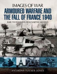
![20th Century Military Uniforms [Grange Books]](https://docer.tips/img/300x300/20th-century-military-uniforms-grange-books_5a9c6d5cd64ab2082986fdf2.jpg)
