$19.95 PANZER TRACTS No.3-4 Panzerbefehlswagen Ausf.D1 , E, H, J, und K development and production from 1935 to 1943 Created by Thomas L. Jentz and Hi...
179 downloads
197 Views
53MB Size
$19.95
PANZER TRACTS No.3-4 Panzerbefehlswagen Ausf.D 1, E, H, J, und K development and production from 1935 to 1943
Created by Thomas L. Jentz and Hilary Louis Doyle Featuring new 1/35th scale drawings ofthe Pz.Bef.Wg.Ausf.D 1, E, H, J, and K
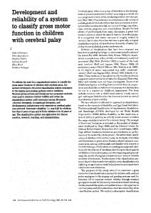
Front Cover Photos: Like all Pz.Bef.Wg. Ausf.J these three issued to the Pz.Nachr.Kp. of the 7.Pz.Div. had 20 mm thick Vorpanzer and retained the vision ports on the turret sides and gunmantle. (HB)
The scale prints of the Pz.Bef.Wg. were drawn at full scale using a CAD program and printed at 1/35 scale.
Thanks are especially due to Ole Leonson (7), Thomas Anderson (7), John Prigent (5), Akira Takiguchi (5), Marcus Jaugits (2), Heiner Duske (2), Karl Pawlas (2), Tony Greenland (2), Karlheinz Muench (1), Werner Regenberg (1), and Henry Blanck (1) for providing copies of rare and unique photos. Photos were also obtained from the Bundesarchiv-Bildarchiv (7), National Archives (3), and Daimler-Benz Archives (1).
Published by Panzer Tracts P.O.Box 312 Boyds, MD 20841 ©Copyright Thomas L. Jentz 2010 ISBN 0-9815382-8-2 www.panzertracts.com
All rights reserved. No portion ofthis publication may be reprinted or reproduced in any fashion or by any means without the express written permission of the publisher.
-'
Introduction Now for the first time Panzer Tracts has created a reliable reference work documenting the history of the Pz.Bef.Wg. Ausf.D 1 to K. Information presented in this Panzer Tracts allows the reader to correctly interpret photographic content from any and all other sources. You can successfully identify the Ausfuehrung (model) of a Pz.Bef.Wg. in a photograph by using the key characteristics correctly identified in this Panzer Tracts. In addition, details of what the far side, top, and rear looked like on any given Pz.Bef.Wg. can be determined when you only have a single photograph of the Panzer that you are interested in. The basic characteristics for each Ausf. were found in surviving parts lists and D652 series manuals. However, these original documents do not contain information on modifications within each Ausf. Since most of the original documents and drawings created by the design finns (Daimler-Benz and Krupp) did not survive and only a few production series modifications were announced in the A.H.M. or H.T.V.Bl., Fgst.Nr. (chassis numbers) are the surviving key to solving the chronological modification puzzle. By themselves Fgst.Nr. can be used to correctly identify the Ausf., but additional information is needed to determine the sequence in which the Pz.Bef.Wg. were actually produced. Fgst.N r. were included in manuals and some modification orders and can be found in surviving strength reports from Panzer units. However, these sources rarely identify the associated assembly plant. Originally Fgst. Nr. series were assigned to each assembly plant in the Waffenamt contract and then recorded on acceptance reports, but over 99.9% of these documents did not survive. We can thank the British for preserving this piece of the puzzle. In their quest to find out how many Panzers were produced by Germany, they collected Fgst.Nr. from knocked-out Panzers and fortunately sometimes noted the associated manufactures logo or three letter code. Relatively few pre-war records on the development of the German Panzers have survived. It was a fortunate stroke of luck when we discovered that the details of Krupp 's pre-war activities survived because they were gathered as evidence of war crimes for the Nuernberg trials. This action preserved Krupp's annual reports with details on their achievements in weapons design and production each year. In addition, production reports from Daimler-Benz survived in their archives. Waffenamt reports on production and operational records on unit strengths were also obtained from the U.S. National Archives and Bundesarchiv Militaerarchiv. Knowing the role of the players involved is key to understanding the development history. The German Army had established a well-controlled weapons development and procurement system involving Inspecktorat 6
(In.6), Wa.Prw.6, and contractors. In.6 was responsible for creating performance requirements for new vehicles wanted by the troops. In.6 also approved the final designs for series production. Wa.Prw.6 created the design specifications, awarded design contracts, and held meetings to control the projects. The commercial designers were informed of the specifications that they had to meet and which components to use. In the case of the Pz.Bef.Wg., Daimler-Benz and Krupp (for the turrets) were awarded contracts by Wa.Prw.6 to develop detailed designs and produce test vehicles. The results were then inspected by In 6 prior to approving further development and production. By knowing which Fgst.Nr. series was assigned to each assembly plant and having the monthly production statistics from the assembly plants, it is possible to determine approximately when any given Pz.Bef.Wg. identified by Fgst.Nr. was produced. Then a list of specific features compiled from thorough examination of photos and survivors identified by Fgst.Nr. can be compiled in chronological order and result in recreation of the order in which significant modifications were introduced. This information can then be used to analyze other photographs of Pz.Bef. Wg. not identified by Fgst.Nr. in an attempt to create the ultimate in accuracy in our scale drawings. The accurate as-built scale drawings in this Panzer Tracts were created by taking hundreds of hours to precisely measure every external part and then spending over two thousand hours to meticulously draw the external features at full scale of the basic Pz.Kpfw.III upon which the Pz.Bef.Wg. were based. The exception being the Pz.Bef. Wg. Ausf.D 1 which was redrawn from original drawings found in the D652 series of manuals. There is no loss in detail with the reduction in scale from being drawn at 1: 1 to being printed at 1:35, because the software now being used to create the printing plates draws the lines, circles, arcs, hexes, and ovals one at a time -just like we did in creating these accurate as-built drawings. As is our high standard, Panzer Tracts are based solely on surviving specimens, wartime photographs, and the content of primary source documents written by those who participated in the design, production, and employment of the Panzers. The time is long overdue for those real experts who designed, produced, and used the Panzerbefehlswagen to have their say. P.S. The Pz.Bef.Wg. Ausf.J was the first model·with a fully traverseable turret and a functioning main gun. It was a conversion from the Pz.Kpfw.III Ausf.J whose assembly started at Henschel and completed later by Daimler-Benz. Even though the Pz.Bef.Wg. Ausf.K appears to be a modified Pz.Kpfw.IV Ausf.F turret, it was specifically created by Krupp as drawing 021B2200 for the "4./Pz.Bef.Wg. Turm". 2200 is not a Pz.Kpfw.IV Gruppen Nr.
3-4-1
Panzerbefehlswagen (Sd.Kfz.266, 267 und 268) DEVELOPMENT During a meeting on 30 and 31 October 1935, In 6 decided to outfit several signals units with Kampfwagen and Fuehrerkampfwagen (Fu) mit Funkgeraet o Two Fuehrerkpfw. (Fu) (Fahrgestell des 3,7 em Geseh.-Kpfw.) for the Naehriehtenzug in a Panzerabteilung. Both outfitted with two 20W ultra-short wave sender sets and two receiver sets with a range of 6 km tn (telephone) and 12 km tg (telegraph). In addition to the four man crew (1 Fuehrer, I Fahrer, and 2 Funker) there was a place for I Offizier. o Two Fuehrerkpfw. (Fu) (Fahrgestell des 3,7 em Geseh.-Kpfw.) for the Naehriehtenzug in a Panzerregiment. One outfitted with a 20W ultra-short range sender set and receiver set with a range of 6 km tn and 12 km tg. The second outfitted with a 30 W sender set and receiver set with a range while moving of 8 km tn and 20 km tg. Both with a four man crew (1 Fuehrer, 1 Fahrer, and 2 Funker) and a place for I Offizier. o Three Fuehrerkpfw. (Fu) (Fahrgestell des 3,7 em Geseh.-Kpfw.) for the NaehriehtenzuK in a Panzerbrigade. One outfitted with a 20W ultra-short range sender set and receiver set with a range of 6 km tn and I2 km tg. The second and third were to be outfitted with a 30W sender set and a receiver set with a range while moving of 8 km tn and 20 km tg. All three with a four man crew (1 Fuehrer, 1 Fahrer, und 2 Funker) and an additional place for 1 Offizier. These "Fuehrerkampfwagen (Fu)" in the Naehrichtenzuege were the combat vehicles for the Abteilungs- or Regiments- or Brigadestab (battalion, regiment, or brigade headquarters). During another meeting on 29Nov35, In 6 made the following decisions on outfitting Panzerkampfwagen and Befehis-Panzerkampfwagen with radio sets and outfitting the NaehriehtenabteilunK in a Panzer-Division with armored radio positions, and also altered previous decisions as follows: o For the Naehrichtenzug in the Panzerabteilung: enter "Grosser Befehls-Panzerkampfwagen" instead of "Fuehrer Kampfwagen (Fu)". One instead of two "20W Ultrakurzwelle-Sender". o For the Panzerdivisions-Naehriehtenabteilung: A total of seven grosse Befehls-Panzerkampfwagen were considered to be necessary, outfitted as follows: o Five each with a 20W ultra-short wave sender set and an ultra-short wave receiver set with a range of 6 km tn and 12 km tg and a 30W sender set and a receiver set with a . range while moving of 8 km tn and 20 km tg. o Two each with Flieger-Ultrakurzwelle-Sender-Geraet and Flieger-Ultrakurzwelle-Empfaenger and a 30W
3-4-2
Sender-Geraet and a Empfaenger with a range while moving of 8 km tn and 20 km tg. Three of the seven grossen (Bef.)-Pz.Kpf.Wg. belong to the Brigade-Naehriehtenzug. On 12 February 1938, Daimler-Benz wrote to Krupp: A Tarnrohr (fake gun tube) is to be made instead of mounting a 3. 7 em Gesehuetz in the 1./Pz.Bef.Kpfw, being developed by Daimler-Benz and it should have the muzzle protector developed by Krupp. Krupp had been responsible for the turret design for the Pz.Kpfw.III series. However, Daimler-Benz was assigned responsibility for the design and assembly of the entire Pz.Bef.Wg. including the Panzerkastenoberteil (superstructure), and Fahrgestell (chassis). By Oktober 1936, the name had officially been changed to the designation that it would carry throughout the rest of the war: "Panzer-Befehlswagen (Sd.Kfz.266, 267 und 268)", abbreviated to "Pz.Bef.Wg.". "gr" was commonly used in operational status reports to identify how many of the larger "grosser"Pz.Bef.Wg. were available in each unit separately from the number of kleiner Pz.Bef.Wg. (Sd.Kfz.265), A notice on Panzer-Befehlswagen (Sd.Kfz.266, 267, 268) from In 6 was released as item 56 in the Allgemeine Heeresmitteilungen (general army, bulletin) dated 7 May 1941: Renaming the Pz.Bef. Wg. is intended to positively identify which P~Bef. Wg.-Aujbau is mounted on which Pz.Kpfw.Ill Fahrgestell. The previously used Ausfuehrung A, B, and C for the Pz.Bef. Wg. is changed to Ausfuehrung Dl, E and H Ausfuelmmg DJ is only used for the Pz.Bef. Wg. The Ausfuehrung E and Hare mounted on the Pz.Kpfw.III, Ausfuehrung E and H Fahrgestell. The Ausfuehrung designations of the Pz.Bef. Wg. AusfuehrungenA, B, and Care to be changed as follows: Ausfuehrung A changed to Ausfuehrung DJ Ausfuehrung B changed to Ausfue/mmg E Ausfuehrung C changed toAusfuelmmg H Initiation of designs of Pz.Bef.Wg.Ausf.J and K Already in experience reports from the campaign in the West in 1940, field units had requested a Pz.Bef.Wg. with a 5 em Kw.K. in a traversable turret. A trial Pz.Bef. Wg. with a 5 em Kw.K. L/42 was ordered that was to be completed in August I94I . Orders were given to produce a limited production run ofPz.Bef.Wg. Ausf.J with 5 em Kw.K. L/42 in 1942. In early I942, the design was initiated for a 4.Serie/Pz.Bef.Wg. with a 5 em Kw.K. L/60 on the Pz.Kpfw. III Ausf.K Fahrgestell. The Pz.Kpfw.III Ausf.K project was discontinued but a series of 50 Pz.Bef.Wg. Ausf.K with a 5 emKw.K. L/60 in the larger Ausf.K turret were ordered and produced starting in late 1942.
Panzerbefehlswagen (Sd.Kfz.267 und 268) Ausfuehrung D 1 , (3c/Z.W. Fahrgestell) Fahrgestell Nummer Serie 60341- 60370 Description Of all the Ausfuehrungen for the Pz.Bef.Wg., only the Ausf.Dl had a Fahrgestell design that was significantly changed from the normal Pz.Kpfw.III series and therefore given the designation "3c/Z.W." Components designed for the 3./Z.W. Serie were normally assigned to Gruppe Nr. 021St32801 to 32899. Some examples of the differences introducedwith the Pz.Bef.Wg. Ausf.D 1 Fahrgestell and components that remained the same for both the Pz.Kpfw.III Ausf.D (3b./Z.W.) and Pz.Bef.Wg. Ausf. D 1 are: Gruppe Nr. GruppeNr. Pz.Kpfw.III Pz.Bef.Wg. Ausf.D Ausf.D1 Component 021St32889 021St33702 Kettenabdeckung 021St29035 _-_ 021St28927 Seitenvorgelege 021St29034 021St28928 Triebrad 021St32873 021St32886 Stuetzrolle 021St32885 021St32898 Stossdaempfer 021St28041 021St32888 Federung 021St11036 021St32887 Laufrollen 021St32871 021St32892 Leitradachse 021St29032 021St29032 Leitrad 021St32880 Andrehvorrichtung 021St32880 021St33722 . 021St33723 N.K.A.V. 021St32894 021St32894 Auspuffanlage Fahr2estell (chassis) The Fahrgestell consists of the following main components: Panzerwanne (armor hull) Motor (engine) Kraftstoffbehaelter (fuel tanks) Kuehler (radiator) Zwischenwelle (drive shaft) Hauptkupplung (main clutch) Schaltgetriebe (transmission) Lenkgetriebe (steering unit) Bremsen (brakes) Seitenvorgelege (final drive) Laufwerk (suspension) Ele~trische Ausruestung (electrical equipment) Werkzeug (tools), Hilfsgeraet (equipment) and Schanzzeug (pionier tools). The general layout of the Fahrgestell is with the Maybach HL 108 TR engine located in the rear ofthe hull, flanked by a radiator on each side. The two fuel tanks are mounted lower in the hull below the radiators and are protected from the engine heat by fire walls. The engine compartment is also separated from the crew compartment
by a firewall with the necessary openings for the main drive shaft, control rods, and electrical lines. Two air filters for the engine and two batteries are located in the crew compartment. The main drive shaft in a tunnel crosses the crew compartment to the main clutch, which is flanged to the Schaltgetriebe (transmission). A Kegeltrieb on the front of the transmission transfers power left and right with two slidable drive shafts to steering units with brakes. The Lenkgetriebe (steering units) are bolted to the inside of the hull and connected to the Seitenvorgelege (final drives) bolted to the outside of the hull. The final drives carry the drive wheel with Triebraeder (drive sprockets) to propel the Gleisskette (tracks). The Pz.-Fahrersitz (driver's seat) is to the left and the Pz.-Funkersitz (radio operator's seat) is to the right of the Schaltgetriebe (transmission). Gas, brakes, and clutch pedals are in front of the driver and Lenkhebel (steering laterals) on both sides of the seat. At the hull rear on the outside on both sides there is an adjustable Kurbelachse (crank axle) for the Leitrad (idler wheel). Between the Triebrad at the front and Leitrad at the rear there are eight Laufrollen (roadwheels). These Laufrollen are mounted as pairs on Doppelschwingen (double swing arins) with leaf springs that in pairs pivot on axles mounted in Kasten (boxes) secured to the hull side. Three Stuetzrollen (return rollers) are located above the Laufrollen on each side. The Gleisketten (tracks) running around all these wheels and propelled by the Triebrad is covered by Kettenabdeckbleche (track guards). Panzerwanne- The Panzerwanne (armor hull) encompasses the enclosed Bugpanzer (forward armor compartment), the open Wannenmittelteil (middle hull section), and the open Heckraum (rear area). The hull is constructed by welding together armor plates with the following thicknesses and at the following angles to vertical: Plate Thickness Angle Glacis 25 mm 86.5° Upper hull front 30 mm 55° Hull front 30.mm 22° Lower hull front 20mm 30mm Sides 30mm Rear 20mm Lower hull rear Belly 15mm The two types of armor used in the construction of the 3c.Z.W. are: o rolled plates up to 14.5 mm thick from homogeneous hard nickel-frei Panzerstahl (153±5 kg/mm2 equal to 435-
3-4-3
465 Brinell Hardness), and rolled plate over 14.5 mm thick from homogeneous nickel-frei Panzerstahl (125±5 kg/ mm 2 equal to 353-382 Brinell Hardness). Armor up to 16 mm thick (including weld seams) was designed and tested to be proof against 7.92 mm S.m.K. (steel-core bullets) fired from rifles or machineguns at a range of 30 meters and striking at 0 degrees. Armor 30 mm thick was designed to be proof against 2 em Pzgr. Rigidity of the side walls is improved by cross braces. The Heckwand (hull rear) is reinforced for mounting the the idler wheel axles. A flange for bolting on the superstructure runs along both upper edges of the side walls and across the rear. The belly is reinforced with formed strips running both across and front to rear. These also serve to secure the drive train components and act as a tunnel for channeling the brake cooling air. Kaesten (boxes) are welded onto the outside of the hull side for mounting the roadwheel swingarms and the idler wheel axle. The following ports and hatches are available for access and to service the automotive components: In the Bu~:panzer: two adjustable 2-piece hatches for the driver and radio operator On the rear: one bolted-hinged cap for the starter crank to the Schwungkraftanlasser (inertial starter), two bolted bolted caps for the idler axle box, one bolted cap for the fan drives. On the belly: Four bolted caps with valves in the Bug and Mannschaftsraum (crew compartment), and four bolted caps under the Kuehlern (radiators) to drain water. One bolted cap under the Kegeltrieb, one under the transmission, and one under the engine; one bolted cap to service the oil filter to drain water. Four bolted caps (two with valves) under the fuel tanks. One bolted Deckel (cover) under the engine-oil tank, and
3-4-4
One bolted Deckel under the engine to service the oil filter. On the firewall between the engine and crew compartment are various bolted caps to service engine components. There are two tow couplings on the front (also used for stowing a tow cable) and two on the rear. Rippled deck plates cover the track guards. The front and rear end of the track guards are hinged so that they can be swung up when driving across a shell-cratered area. Clamps and holders on the deck plates are used to stow tools and equipment. Maybach HL 108 TR - The 12-cylinder Maybach HL 108 TR Motor (gasoline engine) has dry sump lubrication. The 10.8 liter engine has a measured rating of 250 horsepower at 2800 rpm and maximum calculated torque of75 mkg at 2000 rpm. The engine is mounted at three points on rubber bushings. The engine housing is made up of four parts: the V-form block, the lower block, and the two cylinder heads. The crankshaft is mounted in roller bearings between the block and lower block. The connecting rods mounted in pairs on the crankshaft have exchangeable bearing sleeves. The pistons, made out of light metal, have floating connecting pins. The valves are driven by the camshafts mounted at seven points on each of the cylinder heads. The camshaft gear is driven by a interim gear. Pivoting rockers open and close the hanging valves. The tachometer and magnetos are driven by the camshafts. The following auxiliary devices are mounted in and on the engine: 2 oil pumps in the block, 2 circulating oil pumps, 1 oil filter, 1 water pump and 2 fuel pumps driven by belts and pulleys from the crankshaft, I two-barrel Fallstrom-Gelaende-Vergaser (offroad carburetor) with a starter carburetor, 2 magnetos, driven by the camshafts, 1 electrical starter, and I Schwungkraftanlasser
Panzerbefeh swagen (Sd. fz.267 & 268) Ausf.D1
l
Copyright Panzer Tracts 201 0
l
Copyright Panzer Tracts 201 o
0 0 ,...
0 N
rn
t) ns
F...
Cll
N
r::
ns
-
a.
..r::
Cl
·a:
> a. 0
()
0
3-4-5
(inertial starter). Two air filters and one electrical fuel pump are mounted separately from the engine. The Kraftstoff (fuel) is stored in four separate 75 liter tanks. These tanks are located in two pairs on both sides of the engine and protected by a Panzerwand. Zahnradfabrik SSG 76 Schalt~etriebe - The Schaltgetriebe (transmission) is designed for 300 horsepower and a maximum torque of 76 mkg. It is named SSG 76, the letters and numbers associated with the Synchronisiert (synchronized), Sechs-Ganggetriebe (6-speed transmission) rated at 76 mkg. The transmission has six forward and one reverse gear with the following gear ratios and vehicle speeds: 1. Gear 1:9.02 4.3 km/hr 2. Gear 1:4.68 8.3 km/hr 3. Gear 14.1 km/hr 1:2.76 4 . Gear 21.4 km/hr 1:1.82 5. Gear 1: 1.29 30.2 km/hr 6. Gear 1:1 39.0 km/hr Reverse 1:7.3 5.3 km/hr The gears were changed by a stick shift mounted on the side of the transmission. All gears with the exception of first and reverse were synchronized. All six forward gears were beveled and constantly engaged. Reverse gear was square cut. Synchronization made it easier to shift and is easier on the transmission. The Kegeltrieb (differential) housing with a gear ratio of 1:1.059 is bolted to the front of the transmission . There are additonal gear reductions of 1:3.91 and 1:1.862
in the Lenkgetriebe (steering unit) with its planetary gear and 1:4 in the Seitenvorgelege (final drive). The Triebrad (drive wheel) has two sprockets with 20 teeth that engage side holes in the 360 mm wide track links. The track pins are 380 mm long with a head on the inner end and a S-shaped retainer on the outer end. With a track pitch of 120 mm, the unlubricated cast tracks are designated as Kgs 6109/380/120. For maximum traction, each track link has a gripper bar. They are cast as skeleton track links for self-cleaning. A 100-mm-high tooth, cast onto the middle, guides the track link between the double roadwheels and aids in preventing the track from being thrown in heavy clay. The Fahrgestell has a 12 volt Bosch electrical system. A 12 volt Bosch generator with a maximum output of 600 watts feeds the system and loads both 12 volt Varta 105 amp-hour batteries. Both batteries are connected by the starter switch in series to provide the 24 volts needed for the engine's electrical starter motor. Tools are stowed in Werkzeugkasten I (for the tracks, in II to the right of the driver, and in III on the left Kettenabdeckung (track guard). Equipment stowed auside included: a 10 t Wagenwinde Uack), an Unterlegklotz Uack block), a Kettenspanner (track wrench), a Brechstange (wrecking bar), a Feuerloescher (fire extinguisher), Bauart Tatra K 2 S, a S-Haken, a Schleppseil (tow cable) 10m long for 10 t pull , and a Andrehkurbel (starter crank). And inside: a Feuerloescher (fire extinguisher), Bauart Tatra K 2 S and a grosse Drahtschere (wire cutters). Pioneer tools stowed on the Kettenabdeckung are a Ianger Spaten (shovel) and a Halblange Axt.
Left: This is the sixth Pz.Bef.Wg. Ausf.Dl (Fgst.N r. 60346) completed by DaimlerBenz Werk 40 in Berlin-Marienfelde in the Fall of 1938. (AT)
3-4-6
This Page: The curved 30 mm thick turret front was covered by a dummy gun mantle with fake 3.7 em Kw.K. and M.G.34 barrels as well as an operational M.G.34 in a ball mount. (JP & AT)
3-4-7
This Page: While similar in layout with the Pz.Kpfw.III Ausf.D, practically every component was redesigned for the heavier Pz.Bef.Wg.Ausf.Dl with its all-round 30 mm thick armor. (OL & TA)
3-4-8
Above: The drive wheels for the Pz.Bef.Wg.Ausf.Dl had 20 teeth in the drive sprocket (insted of the 21 for a Pz.Kpfw.III Ausf.D). (AT) Below: Even the idler wheel was upgraded with eight spokes added as reinforcement. (JP)
3-4-9
This Page: A unique feature of the Pz.Bef.Wg. Ausf.Dl was the single hatch in the glacis for the driver (but none for the radio operator). There were three pistol ports in the superstructure front and sides instead of a ball mounted machine gun in the front. (OL)
This Page: While stationary, a Kurbelmast "P" could be extended through a hatch in the turret roof to increase the range of the higher power radio sets. (WR)
3-4-11
Panzerbefehlswagen (Sd.Kfz.267 und 268) Ausf.D1, (3c/Z.W. Fahrgestell) Fgst.Nr.Serie 60341 - 60370 Weapons Data: In Turret: Elevation: Traverse: Gunsight:
1 - 7.92 mm M.G.34 -10, + 20 degrees 15 degrees right and left K.Z.F.2 (1.8 x 18 degrees) graduated to 200 meters
In Hull:
3-9 mm M.P.
Ammunition:
2400- 7.92 mm SmK in 32 drum magazines (16 belted bags after June 1940)
Crew:
Commander Adjutant (also machinegunner) 2 Radio Operators Driver
Communication:
Measurements: Length, overall: Width, overall: Width, Hull: Height, overall: Wheel Base: Track Contact: Combat Loaded: Fuel Capacity:
Armor Protection: Hull: Driver's Front Plate Glacis Hull Front Lower Front Plate Superstructure Side Hull Side Hull Rear Deck Belly Turret: Cupola Turret Front Turret Sides Turret Rear Deck
3-4-12
Fu 8 and Fu 6 in Sd.Kfz.267 Fu 7 (Fiiegerboden Fu) and Fu 6 in Sd.Kfz.268 Intercom
5.980 m 2.875 m 1.892 m 2.415 m 2.442 m 3.250 m 18.2 metric ton 300 liters
30 25 30 20 30 30 30 16 15
mm/9 degrees mm/86.5 degrees mm/22 + 55 degrees mm/70 degrees mm/0 degrees mm/0 degrees mm/1 0 + 35 degrees mm/90 + 78 degrees mm/90 degrees
30 mm/0-round 30 mm/round +15 degrees 30 mm/25 degrees 30 mm/25 degrees - round 10 mm/83 + 90 degrees
Automotive Capabilities: Maximum Speed: 39 km/hr Avg. Road Speed: ?? km/hr Cross Country: ?? km/hr Range on Road: ?? km Cross Country: ?? km Grade: 30 degrees Trench Crossing: 2.6 m Step: 57.5 em Fording Depth: 80 em Ground Clearance: 37.5 em Ground Pressure: 0.74 kg/cm 2 Power Ratio: 13.7 HP/ton Steering Ratio: 1.36
Automotive Components: Motor: Maybach HL 108 TR V-12, water-cooled · 10.8 liter gasoline 250 HP@ 2800 rpm Transmission: SSG76 Reverse 5.3 km/hr 4.3 km/hr 1. Gear 2. Gear 8.3 km/hr 3. Gear 14.1 km/hr 21.4 km/hr 4. Gear 5. Gear 30.2 km/hr 6. Gear 39.0 km/hr Steering: Differential Drive: Front sprocket Roadwheels: 8 x 2 per side Tires: Rubber Suspension: Leaf springs Track: Kgs.61 09/380/120 Dry pin 360 mm wide with 120 mm pitch 96 Links per side:
This Page: In addition to the two flexible rod antennas (1.4 m on the right and 2 m on the left) there was a removable frame antennae mounted in sockets on the rear deck. (D655/22)
3-4-13
This Page: There were two visors with vision slits on the right superstructure side and a single visor with vision slit on the left. An armor guard, welded onto the right rear of the stationary turret, protected a porcelain insulator. (D652/22)
3-4-14
This Page: The interior of the Pz.Bef.Wg. Ausf.Dl (D652/22)
3-4-15
I<
Behalter f M.P-Munifion -Behdlfer f. Leuchfmunifion
'1:\ilb ~ 1 ,1\a mpiraum uoru liuf;. iiir · tll .'l.1ci . ~~. ~lu <~i. II '
verschoben
Kurskreise/
Behalter f. M.P Munition
j!li(b 42
3-4-16
.l lampiraum uorn
lin!~
jiir
~J.'l.lcprng. ~lu<~j.
0'
Ersatz- Schufzglaser f. SehklafJP.!!_
Kurbelmast " P"
f.MG 34
tlilb 44
.llom~jroum
linftl 9Jliltc fur
~J.~
60353
This and Opposite Page: The interior of the Pz.Bef.Wg. Ausf.Dl (D652/22) Feldflasche
Behalter f
3-4-17
f. Kretskorn
Behalfff-
t
!5ilb 50 Stam)>fraum ~inten lin!~ fiir ~3·!5•PIDg. ~u~f . D'
f. Kurbelmast rechter
3-4-18
Halter f.
Fe/df/as:he
Behalter f MG.-Munition Behalter f. Leuc:iltmunition
!llilb 52
Stampfraum llorn rcdjtil fiir
~3 . !8cprog. ~lufif.
D'
This and Opposite Page: The interior of the Pz.Bef.Wg. Ausf.Dl (D655/22)
Iter f MP-MJnition
u. Mikrofon !8ilb 53
Stampfraum llorn redjtil fiir !fl3.!8Cf.mlg. 'llui!f. E
3-4-19
Aufbau (superstructures and turrets) for the first three Ausfuehrungen of the Panzerbefehlswagen (Sd.Kfz.266, 267, und 268) - the Ausf.D 1 - Fahrgestell Nummer 60341- 60370, Ausf.E- Fahrgestell Nummer 60501- 60545, and Ausf.H- Fahrgestell Nummer 70001- 70145 Refer to Panzer Tracts 3-2 for details on the Pz.Kpfw.III Ausf.E and H Fahrgestell also used for the Pz.Bef.Wg. Ausf.E and H. General Description The details of the Aufbau for the first three Ausf. of the Pz.Bef.Wg. are described together (with notes about differences between Ausf.) in manual 0652/22 dated 1 October 1941 as follows: The Panzerbefehlswagen is the armored command vehicle for the commanders of the Panzer-Abteilung, Regiment, and Brigade. In its external form it is quite close to the Pz.Kpfw. III. As a Pz.Bef.Wg. it carries the additional designation ofSd.Kfz.266 or 267, or 268, dependent on which type and number ofFunkgeraete (radio sets) are installed. The crew consist of the Kommandant, the Adjutant (also machinegunner), the Pz.-Fahrer (driver) and two Pz.-Funker (radio set operators). The Turm is bolted securely to the Bugpanzer (front superstructure). A cylindrically formed Panzerschutz (armor protector) is on the front wall of the turret. A light metall cast-
ing Blendenabdeckung (mantle cover) is bolted over the Panzerschutz. The openings in the Panzerschutz on the right is for a M.G. Kugelblende 30 (ball mount) and the opening in the left for a Blendensehklappe (vision port). Armament consists of a M.G.34 in the Kugelblende 30 which is aimed by a Zielfernrohr (telescopic gunsight) securely mounted in the Kugelblende. In addition there are three Machinepistolen (MP). Ammunition stowage originally consisted of 32 Doppel-Trommel each holding 75 rounds for a total of 2400 7.92 mm rounds for the M.G.34. After conversion to ammunition sacks containing belted ammunition for the machinegun, starting in June 1940, each Pz.Bef.Wg. had 16 Gurtsaecke mitje 150 Patronen for the M.G.34, 42 Magazine each with 32 Patronen = 1920 for the MP, and in addition 12 Leuchtpatronen (later 24) for the signal pistol. Dependent on the type of radio set, Aufhaengevorrichtungen (radio racks) are hung in the Pz.Bef.Wg. (Sd.Kfz.266 & 267). In addition the Pz.Bef.Wg. has two Stabbantennen (one I ,4 m and one 2 m long), the Kurbelmast "B" (extends 9 m) with the associated Sternantenne, a Rahmenantenne (frame antenna) fastened to the
Panzerbefehlswagen (Sd.Kfz.266, 267, & 268) Ausf.E
Copyright Panzer Tracts 2010
Copyright Panzer Tracts 2010
3-4-21
Heckpanzer, a Stabhochantenne (rod antenna) as well as the necessary Kabeltrommeln (cable drums). The Autbau is not protected against poison gas. Five Gasmasken 30 in holders are the crews' defense against poison gas. The Panzerkastenoberteil (consists of the Bugpanzer mit festem Turm (superstructure with fixed turret and the Heckpanzer (rear deck). Bug- und Heckpanzer can be removed independently from each other. The Bugpanzer protects the Kampfraum (fighting compartment); the Heckpanzer covers the Motorraum and has air intake and exhaust openings to cool the engine. There are four Sehoeffnungen (vision ports) and three MP-Oeffnungen (pistol ports) in the sides of the Bugpanzer. The Sehoeffnungen are closed by Sehklappen (visors), the MP-Oeffnungen are closed by pivotable MP-Kiappen (armor caps) The MP-Kiappe in the Bugpanzer (driver's front plate) is surrounded by a Rahmen (armor guard) for camouflage to make the it look like a Kugelblende (MG ball mount). There is a hole in the right side of the Bugpanzer for the antenna mount for the 1.4 m-Stabantenne and another hole in the left side toward the rear for the 2 m Stabantenne. The holes are protected against penetration by armor piercing ammunition by a Schutzrohr (protective tube) made out of Panzerstahl. Traghaken (hooks) for lifting and lowering the Heckpanzer, Bugpanzer and Turm are to be used for securing Tarnmitteln (camouflage).
3-4-22
Inside the Kampfraum are holders for 12 Ersatzschutzglaeser (replacement glass blocks) for the Sehklappen, five gasmask holders, Kaesten for MG-, MP-, and Leuchtmunition (signal flares), holders for three MP, one Verbandkasten (first aid kit), two Aufhaengevorrichtungen (hanging frames) for Funkgeraete (radio sets) (each for one Sender and one Empfaenger (receiver)) and one Haltearm for the Kurbelmast "B", holders for three Kochgeschirre (mess kits) and five Feldflaschen (water bottles). The sliding Fahreroptik (driver's periscopes) are located on the inside behind the Fahrersehklappe (driver's visor). A Sprechschlauch (speaking tube) is used for the Kommandant to talk to the Adjutant and Pz.-Fahrer. The Heckpanzer protects the Motorraum (engine compartment). There are four hatches with Klappen (hatch lids) in the top for access to the engine. To increase cooling air flow the Klappen can be held open by a Rastenheber (lifting arms). Kuehllufteintrittsoeffnungen (cooling air intake openings) are located on the right and left outer side of the Heckpanzer. Kuehlluftaustritt (cooling air exhaust) is on the underside of the Heckpanzer. Both the cooling air intake and exhaust are protected by sloping armor. The Gitter (screen) on the cooling air intake hinders throwing in Handgranaten. Five Klemmhalter (clamps) for the Rahmenantenne (frame antenna) are bolted to the deck of the Heckpanzer. In addition, there are retainers for the Abschleppseil (tow cable) on the deck of the Heckpanzer.
j
Panzerbefehlswagen (Sd.Kfz.266, 267, & 268) Ausf.H
I "
"
"
"
"
I
j
"
Copyright Panzer Tracts 201 0
Copyright Panzer Tracts 2010
0 ,.... 0
C'll
.= II)
(J
co
...
C1)
N
r:::
co
c.
3-4-23
Bu2panzer and Components - The Bugpanzer consists of armor plates welded together to form a rectangular structure with the following thicknesses (in mm) and angles (to the vertical): Plate Ausf.D 1 und E Ausf.H Front 30/9° 30+30/9° Side 30/0° 30/0° Deck 16/90° 16/90° There are three Sehklappen (vision ports) in the Bugpanzer - one to the left of the driver, one to the direct right of the radio operator, and one to right rear of the radio operator. There is one Fahrersehklappe (driver's visor) in the driver's front plate and three MP-Klappen (MP ports)- one in the front, one in the left side, and one in the right side. The Sehklappe 30 mounted to the left of the driver in the side wall has a 8 mm wide vision slit and a 90-mm-thick Glasbloek. A Sehklappe 30 without a vision slit is mounted to the right of the radio operator. The Ausf.D, has a Fahrersehklappe 30 (vision port) mounted in the superstructure front to provide the driver with direct vision when opened. The 90-mm-thick Glasbloek mounted behind the vision port protects against lead splash, shell fragments, and direct hits from bullets. To improve protection from hits, the partitioned driver's visor was replaced with a Drehsehklappe (pivoting visor). This Fahrersehklappe 30 (021 C 9288) for the Pz.Bef.Wg. Ausf.E and H consisted of a frame bolted to the superstructure front with the large vision port covered by the Drehsehklappe. A 90-mm-thick replaceable glass block protected the eyes against lead splash, shell splinters, and direct hits from lead bullets. When the Fahrersehklappe must be closed during combat, there are two holes above the Fahrersehklappe for viewing through the twin periscopic Fahreroptik K.F.F.l (earlier designation K.F.F.III) from Askania in the Ausf.D, . The K.F.F.l has a 1 x magnification and a 65 degree field of view. The K.F.F.2 Fahreroptik is mounted in the Ausf.E and H with a 1.15 x magnification and a 50 degree field of view. Funk2eraet (Radio Sets)- The Pz.Bef.Wg. has the additional designation Sd.Kfz.266, 267, or 268 based on the radio sets that are installed. The Sd.Kfz.266 has two Funkgeraete. One "Fu 6 (SE 20 U)" made up from a 20 Watt Sender and an UItrakurzwellen Empfaenger and a "Fu 2 (EU)" that is an Ultrakurzwellen Empfaenger. The Sd.Kfz.267 has two Funkgeraete. One "Fu 6 (SE 20 U)" made up from a 20 Watt Sender and an UItrakurzwellen Empfaenger and a "Fu 8 (SE 30)" consisting of a 30 Watt Mittelwellen Sender and a Mittelwellen Empfaenger.
3-4-24
The Sd.Kfz.268 also has two Funkgeraete. One "Fu 6 (SE 20 U)" made up from a 20 Watt Sender and an Ultrakurzwellen Empfaenger and a "Fu 7 (SE 20 U) (Fiiegerboden Fu)" consisting of a 20 Watt Sender and a Ultrakurzwellen Empfaenger.
Heekpanzer - The Heekpanzer protects the engine compartment. The Heekpanzer is constructed by welding together armor plates with the following thicknesses (in mm) and at the following angles to vertical: Plate Ausf.D 1 Ausf.E Ausf.H Deck 16/87-i8o 16/87-75° 16/87-75° Sides 30/0° 30/0° 30/0° Rear 30/l oo 20/30° 30/30° Two hatches on the rear deck provide access to the engine and fuel tank, and two hatches on the sloping rear deck provide access to the fan drives. Armored cooling air intakes are located on both sides of the Heekpanzer. Turm (Turret and Componets) - The turret is bolted to the Bugpanzer and cannot be traversed. A cylindrically formed Panzersehutz (armor protector) is on the front wall of the turret. A light metal casting Blendenabdeekung (mantle cover) is bolted over the Panzersehutz. The openings in the Panzersehutz on the right is for a M.G. Kugelblende 30 (ball mount) and the opening in the left for a Blendensehklappe (vision port). There is an aluminum alloy cover bolted to the turret front with a 3.7 em (5 em on later Ausf.H) dummy gun to camouflage the turret front to resemble a normal Pz.Kpfw.III. Note: A cast aluminum alloy dummy 5 em Kw.K. was insstalled on Pz.Bef.Wg.Ausf.H Fgst.Nr. 70139. The Turmgehaeuse is constructed by welding together armor plates with the following thicknesses (in mm) and at the following angles to vertical: Plate Ausf.D, und E Ausf.H Front 30/round-15° 30/round-15° Sides 30/25° 30/25° Rear 30/25° and 0°/round 30/1 oo Roof 10/90 and 83° 10/90 and 83° Cupola 30 mm drum plus cast armor shutters Armament consists of a M.G.34 in the Kugelblende which can be traversed 15 degrees to the right and left and has an elevation arc from minus 10 to plus 20 degrees. The machinegun is aimed using the K.Z.F.2 telescopic gunsight with 1.8 x magnification and 18 degree field of view. An M.G.34 with a Panzermantel protecting the gun barrel was introduced with the Ausf.H. There are two circular openings in the turret roofone for the Kurbelmast "B" (extendable mast for long range radio transmission) the other for the Turmspaehfernrohr (T.S.F.l). The traversable binocular peri scopic T.S.F.l with 3 x magnification and a 20 degree field of view is used by the commander for observation. The
This Page: Due to delays in producing the pivoting 30 mm Fahrersehklappe, an expedient driver's visor was installed on Pz.Bef.Wg. Ausf.E produced before September 1939. (TG)
3-4-25
opening in the turret roof for the T.S.F.l can also be used for signal flags and firing signal flares. There is also an opening in the right rear turret plate for the cable from the Rahmenantenne (frame antenna) to the radio sets, which is protected by a Panzerkappe (armor cap). Kommandantenkuppel (commander's cupola) Ausf.Dl und E- AKommandantenkuppel (commander's cupola) is bolted onto the rear of the turret roof. It serves as a crew hatch and for observation by the commander. There are five vision slits cut into the side that can be opened or closed by independently adjustable
3-4-26
Schieber (slides). A 90 mm thick safety glass block is mounted behind each vision slit. Kommandantenkuppel (commander's cupola) Ausf.H - The Kommandantenkuppel (021 B 39032) for the Ausf.H still has five vision slits which are covered or opened by five independantly adjustable Schieber (slides) that are narrower than those on previous cupola. The armor castings for the Schieber and fixed armor guards between the Schieber are also much thicker than on the previous cupola. A 90 mm thick safety glass block whichprotects against lead splash, shell fragments, and direct hits from lead bullets, is mounted behind each vision slit.
Above: This Pz.Bef.Wg. Ausf.E with the II.Abt./Pz.Rgt.2 of the l.Pz.Div in Belgium in May 1940 has a white aerial recognition panel painted on the rear deck. (JP) Below: The pattern of the two tone (Dunkelgrau/Dunkelbraun) camouflage scheme is evident on the front of this Pz.Bef.Wg. Ausf.E photographed in 1940. (NA)
3-4-27
'!\ilb 36 :I:urm, l!inblid burcf) ncf)tc l!in[tciglufc, jiir
~3.'!\cp!llg. ~lu Bf.
E
"p"
M P- Klaf?R.e
mandantensitz
3-4-28
vers:hoben
Behalter f. £rsdtz-KFF 2
B ehiitter f. M.P-Munition
Haller f Gasmaske
Ersatz -5chutzg laser f.
F"ahr;;:;ehklagJ~
23ilb 4a S\'ampftaum \Jom lin!s jut 'l\&.23cj.'ll.lg. 2htsf. g unb H
I This and Opposite Page: The interior of a Pz.Bef. W g. Ausf.E. (D655/22)
Luft fitt er
Sammler
3-4-29
f MG.- Zweibein
Feldflaschen
This Page: The interior of a Pz.Bef.Wg. Ausf.H with belted 7.92 mm ammunition in bags. (D652/22)
Kommandantensitz
3-4-30
-
Above: The Schirmantenne mounted on top of the extended Kurbelmast on this Pz.Bef.Wg.Ausf.H. The antenna lead was coiled in an Aufspuler mounted on the right turret side and was fed out through a pivoting guide in an armor cap bolted to the top of the turret. (BA L24881)
3-4-31
Above: At the start of production the Pz.Bef.Wg. Ausf.H stiU had the same drive sprocket wheel and idler as its predecessor Ausf.E but had wider Kgs 61/400/120 tracks. (OL)
Left and Right: Two Pz.Bef.Wg. Ausf.H with Pz.Rgt. 7 of the lO.Pz.Div. with the cast drive sprocket wheel designed for the wider tracks. Most of the Pz.Bef.Wg. Ausf.H in the first contract for 145 still had the same idler wheel as the Ausf.E predecessor. (MJ)
1
Above: Machining holes in the hull side ofWanne Nr. 70035 for a Pz.Bef.Wg. Ausf.H for the swing arm and torsion bar mounts at Daimler-Benz Werk 40 in Berlin. (DB)
3-4-33
This Page: Pz.Bef.Wg. Ausf.H (Fgst.Nr.70074 followed by 70045) issued to the Pz.Nachr.Kp. of the 18.Pz.Div. still had the fake 3.7 em Kw.K. and a second fake M.G.34 barrel. (AT& TA)
3-4-34
Above: Another Pz.Bef.Wg. Ausf.H (tactical number B02) with the 18.Pz.Div. (JP)
Right: A Pz.Bef.Wg. Ausf. H with Pz.Rgt.18 of the 18.Pz.Div. has been modified as a Tauchpanzer. (TA)
Above: The hole for the second fake machinegun has been plugged on this Pz.Bef.Wg. Ausf.H with a fake 5 em Kw.K. Ths antenna lead (coming out ofthe armor cap on the right side of the turret roof) was attached to the Schirmantenne at the top of the extended Kurbelmast. (TA) Below: This Pz.Bef.Wg. Ausf.H (Fgst.Nr. 70170) produced as part of the second contract for 30 in January 1942, has a fake 5 em Kw.K. instead of the 3.7 em Kw.K. (BA 216/40/417)
3-4-36
Above: A removable frame antenna for the long range radio sets was mounted in sockets on the rear deck of the Pz.Bef.Wg.Ausf.H. (HD)
Right: Most of the Pz.Bef.Wg.Ausf.H producted under the first contract for 145 still had the same idler wheel as the Ausf.E and did not have an armor guard protecting the NKAV (smoke grenade rack) mounted on the left hull rear. (HD)
3-4-37
Sehklappe.1inks v.Pz.-Fahrer Gurt sacke
Halt er fur M. P.
~ilb ai
~urm, liinb!id burdj redjlc l!:iuflcig!ule, jiir ~3-~cj. mlg. 2!uilj. H
This and Opposite Page: The interior of a Pz.Bef.Wg. Ausf.H (D652/22)
verschoben
B ehaJier f Ersatz-KFF 2
Eeh Jifer f. M.P-Muni fion Hatler f. Gasmaske
Ersatz -5chufzgli:iser f.
rah~hklaf:1J~
~ilb 4H
3-4-38
.l lampfraum \lorn linlil fiir ~.j . !Bcpmg. 2!uilf. R unb H
f Kochgeschirr
'Bilb J7
.\tam\Jfraum
~intcn
linfs fiir \}!3.-Bcpmg.
~lu B f .
H
Halter f
Hatter f retdfldsd!e
3-4-39
Panzerbefehlswagen (5 em Kw.K. L/42) (Sd.Kfz.266, 267, und 268) Ausfuehrung J Fahrgestell Nummer Serie 73631- 73763 Already in experience reports from the campaign in the West in 1940, field units had requested a Pz.Bef.Wg. with a Kw.K. in a traversable turret. On 6 March 1941, Wa Pruef 6 informed Wa J Rue that fifteen 5 em Kw.K. had been ordered for Krupp with delivery of the first gun for the new Pz.Bef.Wg. turret scheduled for the end of the month. On 7 August 1941, Krupp reported that a Geraet 5-261 , a 5 em Kw.K. L/42 in a Pz.Bef.Wg. was being developed. Originally known as the Pz.Bef.Wg.III Ausf.D, the name was subsequently changed to Pz.Bef.Wg. Ausf.J as listed in TL 21/3043 along with the Pz.Bef.Wg. Ausf. D1, E, H, und K. The development history of the Pz.Bef.W2. mit 5 em auf Fahr2estell Pz.Kpfw.III was recorded by Wa Pruef 6 on data sheet D 26 dated 1 July 1942, as follows: Develop a Pz.Bef.Wg. with a traverseable turret with a 5 em Kw.K. in a turret mounted on a Pz.Kpfw.III (S.Serie) Fahrgestell. Development requested by the troops with Daimler-Benz contracted to design the Aufbau and Krupp, Essen to design the turret. One trial Pz.Bef.Wg. was ordered that was to be completed by 1 August 1941. With 50 mm thick front and 30 mm thick side armor, armed with a 5 em Kw.K. and three MP, and manned by a crew of five, the Pz.Bef.Wg. was estimated to weigh 21.5 metric tons. Mass production was projected to begin in July-August 1942. 81 Pz.Kpfw.III Ausf.J mit 5 em Kw.K. L/42 were by Daimler-Benz Werk 40 "behelfsmaessig" converted into Pz.Bef. W g .. These 81 Pz.Kpfw.III Ausf.J in Fgst. Nr.Serie 73631- 73763 were completed by Henschel from
February to April 1942 and then later delivered to DaimlerBenz Werk 40 for conversion. Refer to Panzer Tracts 3-3 for details on the Pz.Kpfw.III Ausf.J Fahrgestell also used for the Pz.Bef. Wg.Ausf.J. The Pz.Kpfw.III was converted to a Pz.Bef.Wg. by installing racks for the radio sets needed in a Sd.Kfz.266, 267, or 268. A 1.4 m Stabantenne was added to the left superstructue side, the 2 m Stabantenne remained on the right side, and an armor pot was welded to the middle of the rear deck (toward the rear) to protect the insulator upon which the long range Sternantenne was mounted. To obtain additional space for the radio sets in the right front, the Kugelblende 50 with M.G.34 was replaced by a MP-Klappe and the M.G.34 mount in the turret was deleted. Vorpanzer made out of 20 mm thick plates was mounted on a frame in front of the gun mantle and also mounted on spacers on the superstructure front. About April 1942, the Heckpanzer was standardized for increased ventilation with Lueftungshauben (ventilation hoods) on the hatch lids of all Pz.Kpfw.III, whether they were intended to be sent to the Tropen or not. The twin hatches over the engine now had single piece engine hatch covers that were hinged at the front and secured by bolts at the rear. Three larger Lueftungshauben (ventilation hoods) mounted parallel to the hull side were bolted onto the engine hatch covers (two on the left and one on the right). The Luefterklappen (ventilator hatches) over the fans at the rear of the Heckpanzer were
Panzerbefehlswagen (Sd.Kfz.266, 267, & 268) Ausf.J
j
o®(0Jcvo 0
0
0
I
j
0
Copyright Panzer Tracts 2010
Copyright Panzer Tracts 2010
0 ,.... 0 C\1
Ill
u
CIS
F
...
Q)
0
N
1:
CIS
a. 1:
..
Cl
·;::
> a. 0
u
3-4-41
increased in size and had the same type ofLueftungshauben as the engine hatches - but mounted perpendicular to the hull side. Starting in September 1942, series production commenced with two Nebelkerzen-Wurfgeraeten (smoke grenade di schargers) mounted on the turret sides and secured using the bolts for the lifting hooks. Each Geraet
had three Wurfbecher fixed at different side angles and elevations. Schneli-Nebelkerzen 39 were propelled out of the Wurfbecher by an electrical Zuendschraube (C 23) which was fired by pushing one of three buttons on the firing panel inside the turret. Starting in May 1943, the Pz.Bef.Wg.Ausf.J were backfitted with Schuerzen.
Above: Like all Pz.Bef.Wg. Ausf.J these three issued to the Pz.Nachr.Kp. ofthe 7.Pz.Div. had 20 mm thick Vorpanzer and retained the vision ports on the turret sides and gun mantle. (HB) Below: The Pz.Bef.Wg. Ausf.J were backfitted with Schuerzen starting in May 1943. (BA )
3-4-42
This Page: Instead of a frame antenna a Sternantenne was mounted on a porcelain insulator protected by an armored pot on the rear deck of the Pz.Bef.Wg. Ausf.J. (BA)
3-4-43
\
I
This Page: Converted from Pz.Kpfw.III Ausf.J the Pz.Bef.Wg. Ausf.J retained the M.G.34 in the turret but the ball mount in the superstructure front was replaced by an armored guard for an M.P. (KRP)
3-4-44
This Page: Starting in September 1942, series production commenced with two NebelkerzenWurfgeraeten (smoke grenade dischargers) mounted on the turret sides of the Pz.Bef.Wg. Ausf.J. (NA)
3-4-45
Above: The vision port for the radio operator was retained in the gun mantle of all Pz.Bef.Wg. Ausf.J like this one issued to the 7.Pz.Div. (TA) Below: A Pz.Kpfw.III Ausf.L turret has been backfitted onto this Pz.Bef.Wg. Ausf.J. (BA)
This Page: This Pz.Bef.Wg. Ausf.J was produced with the same armor caps protecting openings cut in the hatches for increased engine cooling air flow as fitted to the earlier Pz.Bef.Wg. Ausf.H. These were changed to single piece hatches and larger ventilation hatches with forged armor caps that were introduced during the production run starting about April 1942. (TA & KHM)
3-4-47
Panzerbefehlswagen (5 em Kw.K. L/60) (Sd.Kfz.266, 267, und 268) Ausfuehrung K, (4.Serie Pz.Bef.Wg.) Fahrgestell Nummer Serie 70201- 70250 Turret Desi~n -Drawing (021 B 2200) for the 4./Pz.Bef.Wg.-Turm, based on the B.W.40 Turm, was accepted on 15 April 1942. Like the turret for the B.W.40, the Turm-Panzergehaeuse (021 B 2220) had a similar shape and size as a normal Pz.Kpfw.IV turret and was mounted on a Turmkugellager (turret ball race) (021 C 33861), adopted from the Pz.Kpfw.IV Ausf.E. There was a schmale Walzenblende (narrow gun mantle) (021 B 2222) with a 5 em Kw.K.39 L/60 on the turret front beside a Beobachtungs-Sehklappe (observation vision port) (021 B 2221). With its pivoting shutter the Beobachtungs-Sehklappe was very similar to a normal Fahrersehklappe 50 (driver's visor). The following parts newly designed for the Pz.Bef.Wg. Ausf.K, included a: Turmschwenkwerk (turret traverse mechanism) (021 B 2223), Hoehenrichtmaschine (gun elevation mechanism) (021 B 2224), Kampfwagenkanone-Zurrung (gun travel lock) (021 B 2226), Turmzurrung am Turmkranz (turret travel lock) (021 C 2228), Kommandantensitz (commander's seat) (021 B 2229) and Signalklappe vorn am Turmdach (signal port) (021 C 2231). The left Sehklappe ohne Sehschlitz (vision port without viewing slit) (021 B 196) was taken over from the Pz.Kpfw.IV Ausf.F and the M.P.Klappen an der
3-4-48
Turmriickwand (021 B 41457), rechte Sehklappe mit Sehschlitz (021 B 41459), Iinke Turmluke (crew hatch) (021 B 41460) und rechte Turmluke (021 B 41461) taken over from the Kpfw.III Ausf.M. A newly designed Kommandantenkupola (commander's cupola) (021 B 2481) had a single piece hatch lid and thicker castings for the Schildring. There were sti ll five vision slits with upper and lower Schiebern to open and close them. A 90 mm thick Schutzglas (glass block) located inside each vision slit protected the commander from shell fragments, bullet splash, and direct hits from lead bullets. Two Nebelk~rzen-Wurfgeraeten (smoke grenade dischargers) were mounted on the turret sides and secured using the bolts for the lifting hooks. Each Geraet had three Wurfbecher fixed at different side angles and elevations. Schnell-Nebelkerzen 39 were propelled out of the Wurfbecher by an electrical Zuendschraube (C 23) which was fired by pushing one of three buttons on the firing panel inside the turret. The Fahrgestell and Heckpanzerung were taken over from the Pz.Kpfw.III Ausf.M and outfitted for submerged fording. Refer to Panzer Tracts 3-3 for details on the Pz.Kpfw.III Ausf.M Fahrgestell also used for the Pz.Bef.Wg. Ausf.K. Racks for the radio sets needed in a Sd.Kfz.266,
j
Copyright Panzer Tracts 2010
Copyright Panzer Tracts 201 0
... 0 0
C'll
Ill
ti
n:l
.=...
Q)
;;==~lin a.~
®
3-4-49
267, or 268 were installed in the Pz.Bef.Wg. Ausf.K. A 1.4 m Stabantenne was added to the left superstructue side, the 2 m Stabantenne remained on the right side, and an armor pot was welded to the middle of the rear deck (toward the rear) to protect the insulator upon which the long range Sternantenne was mounted. To obtain additional space for the radio sets in the
right front, the Kugelblende 50 with M.G.34 was replaced by a MP-Kiappe and the M.G.34 mount in the turret was deleted. The 50 Pz.Bef.Wg. Ausf.K were completed by Daimler-Benz Werk 40 from December 1942 to February 1943. Starting in May 1943, the Pz.Bef.Wg.Ausf.K were back:fitted with Schuerzen.
This Page: While based on the size and shape of the Pz.Kpfw.IV, the turret for the Pz.Bef.Wg. Ausf.K was designed specifically for a command tank with an operational5 em Kw.K. L/60 gun. (JP & AT)
Above: Instead of adopting the Nebelkerzen-Wurfgeraet from the Pz.Kpfw.III, it was redesigned with the top projector barrel slanted farther out and the lower barrel pointing forward. (OL) Below: The Pz.Bef.Wg. Ausf.K had the same chassis rigged for deep fording as the Pz.Kpfw.III Ausf.M with flaps and seals to close all of the hull openings and a special muffler. (OL)
3-4-51
Above: A row of three Pz.Bef.Wg. Ausf.K behind a Pz.Bef.Wg. Ausf.J. The Pz.Bef.Wg. Ausf.K had a new cupola with a single piece hatch lid, a pivoting visor in the turret front for the loader and an armor guard for an MP port in the superstructure front instead of a M.G. ball mount. (OL) Below: This Pz.Bef.Wg. Ausf.K was issued to the Pz.Nachr.Kp. of the 16.Pz.Div. (BA 665/682/33)
3-4-52
Above: The small "basket" mounted behind the cupola on the Pz.Bef.Wg. Ausf.K was intended to hold ignited orange signal flares. (TA)
3-4-53
PRODUCTION A new design for a Pz.Bef.Wg. on a Pz.Kpfw.III chassis had been requested in October 1935. As reported on 30 September 1936, a 0-Serie of30 gr.Pz.Bef.Wg. with radio receivers and special equipment on Pz.Kpfw.III Fahrgestell had been ordered by In 6 to be completed during the period ofOctober 1937 to February 1938 (with a second trial series ordered to start in March 1938 but mass production wasn't planned to occur before the Fall of 1938). The D.E.W. steel plant was contracted to roll the armor plates, cut and bend them into the desired shapes, and weld the turret, superstructure, and hull armor bodies together for the 3c.Z.W. (Pz.Bef.Wg. Ausf.D). However, delays occurred. There wasn ' t a single gr.Pz.Bef.Wg. in the army inventory as of 1 January or 1 April 1938, nor were any expected to be delivered by June 1938, but a total of 12 were expected in the third quarter. However, there were only two gr.Pz.Bef.Wg. in the army inventory dated I October 1938. WaJRue did not start their monthly production reports until1939. On 20 February 1939, WaJRue reported that 26 gr.Pz.Bef.Wg. had been completed since 1 April 1938, including 6 in December and 0 in January 1939. The Pz.Bef.Wg. Ausf.D 1 was produced as the Sd. Kfz.267 (total of 24) and 268 (total of 6), whi le both the Ausf.E and H were produced as Sd.Kfz.266, 267, and 268. On 25 April 1940, Wa J Rue reported that as of 1 Apri l 1940 there were sti ll 151 gr.Pz.Bef.Wg. to be delivered from those ordered to date by In 6. The Ausf.D 1 production run of 30 had been completed in March 1939 and the 45 Ausf.E had been completed in February 1940. This 151 does not exactly match the I45 Ausf.H that had been ordered by In6 but proves that they had been ordered by early 1940. In manual H.Dv.47/l3 dated 25 April 1941 , the Pz.Bef.Wg. previously authorized by In 6 are reported as: Pz.Bef.Wg. Ausf.D Fgst.Nr. 60341-60370 Pz.Bef.Wg. Ausf.E Fgst.Nr. 60501-60545 Pz.Bef.Wg. Ausf.H Fgst.Nr. 70001-70145 Pz.Bef.Wg. Ausf.H is still li sted as a total of 145 (Fgst.Nr. 70001 - 70145) in manual D652/22 dated 1 October 1941, even though another 30 Ausf.H (Fgst.N r. 70146- 70175) had been ordered by In 6 and were completed by Daimler-Benz in December 194I /January 1942. On 28 July 1942, Daimler-Benz reported that out of the schedu led 10, zero behelfsmaessi2en (expedient make shift) Panzerbefehlswagen had been delivered. These were to be the start of the 81 Pz.Bef.Wg. Ausf.J that were actually completed from August to November 1942. Daimler-Benz was scheduled to start completion ofthe 4.Pz.Bef.Wg. (Ausf.K) at the rate of 10 in Sep, 10 in Oct, 10 in Nov, I 0 in Dec42 . But, due to delays actually completed 36 in December I942, 13 in January and 1 in February 1943 .
3-4-54
Table 1 - Pz.Bef.Wg. Production as Reported by Wa J Rue 1939 1940 1941 1942 Month 1938 4E 16 H 14H January 0 1E 20H 0 February 0 4 D1 24H 0 March 0 April 0 0 22H 0 14H May 0 0 0 0 5H 0 June 0 13 H July 3E 0 0 5E 0 0 41 J August 2H 12 J 7E 0 September October 10 E 0 0 27 J 8E 2H 1J 0 November 26*D1 7E 27H 16H 36K December 131 26* 44 34 132 Total *26 completed since 1Apr38, including 6 in Dec38 Note Dl - Pz.Bef.Wg. Ausf.D1 Note E- Pz.Bef.Wg. Ausf.E Note H- Pz.Bef.Wg. Ausf.H Note J- rebuilt into Pz.Bef.Wg. from Pz.Kpfw.III Note K- Pz.Bef.Wg. m. 5 em Kw.K. L/60 (schmal) ORGANIZATION AND ISSUE On 1 March 1939, it was determined that 39 Sd.Kfz.266, 57 Sd.Kfz.267, and 10 Sd.Kfz.268 were needed to completely outfit the peacetime army (of which only 24 Sd.Kfz.267 and 6 Sd.Kfz.268 were available). Before the start of the war, by 15 August 1939 the 30 Ausf.D 1 had been issued as one Sd.Kfz.267 to Pz.Rgt.1 through 8, one Sd.Kfz.267 to Pz.Rgt.ll, 15, 25, 31, 35, and 36, one Sd.Kfz.267 to Pz.N.A.77 and 79, one Sd.Kfz.267 to the 4. and 6.Pz.Brig. and two Sd.Kfz.267 to Pz.N.A.37, 38, and 39. The six Sd.Kfz.268 were issued one each to Pz.N.A.37, 38, 39, 77, and 79 and the 4.Pz. Brig. A total of 32 gr.Pz.Bef.Wg. were reported as being available for the army on 1 September 1939 with another 11 available in the HZa for issue on I October 1939. On 7 October 1939 the army reported that 13 gr.Pz.Bef.Wg. had been temporary losses during the Polish campaign . Unfortunately, the Panzer units did not report the number ofgr.Pz.Bef.Wg. in their possession separately from the ki.Pz.Bef.Wg. in their strength reports after the war started and on into 1941. In Heeres Panzerprogramm 41 dated 30 May 1941 the Heereswaffenamt calculated that a total of 572 Pz.Bef. Wg. would need to be produced to fill an expanded army of20 Pz.Div. (including 20 s.Pz.Rgt.) and 10 lnf.Div. (mot.) of which 90 were to be produced by I April 1942 and 210 by 1 April 1943.
Or2anization - While the Pz.Bef.Wg. were ori ginally intended fo r the Pz.Abt. and Pz.Rgt. headquarters armored signal platoon, they were also authorized fo r Pz.Brig. headquarters and the Panzer-Funk-Kompanie in the Pz.Div. as revealed in the fo llowing K.St.N. list. Tables ofOr~anization for Units with Pz.Bef.W~. K.St.N. Date Unit Pz.Bef..W2. 971 10ct37 Pz.Fu.Kp.a 7 (5 267, 2 268) 1194 10ct37* Pz.Rgt.Stab N.Zug 2 267 1195 10ct38* Pz.Abt. N.Zug 1 266 2 267 1194(Sd) 1Sep39 Pz.Rgt.Stab N.Zug 1150(Sd) 1Sep39 Pz.Abt.Stbs.Kp.N.Zug 2 266 1194(Sd) 1Feb41 Pz.Rgt.Stab N.Zug 2 267 1150(Sd) 1Feb41 Pz.Abt.Stbs.Kp.N.Zug 2 266 1194 1Nov41 Pz.Rgt.Stab N.Zug 2 1150 1Nov41 Pz.Abt.Stbs.Kp.N.Zug 2 266 1103 1Nov41 Pz.Rgt.Stb.Kp. 2 1150d 15Aug42 s.Pz.Abt.Stbs.Kp.N.Zug 1 268+ 1150b 25Jan43 Pz.Abt.Stbs.Kp.b N.Zug 2* 1150f 1Feb43 Pz.Abt.f Stbs.Kp. 2 (267+ 268) 10Apr43 Pz.Sturmg.Abt. Stbs.Kp. 3# 1157 3# 1156 5May43 Sturmpz.Abt.Stbs.Kp. 1150b 1Nov43 Pz.Abt.Stbs.Kp.b N.Zug 2* 971 1May44 Pz.Div.Fu.Kp. 2 268 K.St.N.1194 dated 1Oct3 7 and K.St.N.1195 dated 1Oct38 were both still in effect in 1939 and on into mid1940. +One Pz.Kpfw.Ill (5 em) als Pz.Bef.Wg. (Sd.Kfz.268) *Three Pz.Kpfw.III (5 em) of which two as Pz.Bef.Wg. # Three Pz.Kpfw.III L42 als Pz.Bef.Wg. ln the Fall of 1942, un its such as the 6., 7., and 1O.Pz.Div. and the three SS-Pz.Gren.Div. were issued 9 Pz.Bef.Wg. Ausf.J with 5 em Kw.K. L/42 instead of the two Pz.Bef.Wg. and one Pz.Kpfw.III (5 em) for the Pz.Abt. and Pz.Rgt.Stab Nachrichten Zug authori zed by K.St.N. dated I November 1941.
Units with Identified Pz.Bef.W~.Ausf.H Unit Date F2st.Nr. 9.Pz.Div. Oct41 70004. 70022, 70101 , 70120 5.Pz.Div. Jun44 70008, 70057, 70110, 70127, 70129, 70145 Jun44 70012,70052 4.Pz.Div. Jun43 70029 3.Pz.Div. Dec43 70034, 70135, 70165 25.Pz.Div. Mar43 70060, 70172, 70175 11.Pz.Div. Jan43 70070, 70147 23.Pz.Div. Nov43 70089,70102,70104, 8.Pz.Div. Apr43 70119,70152, 70167 G.D. Mar43 70159 Reich Apr43 70163 LSSAH 16.Inf.Div. Jan43 70166 Units with Identified Pz.Bef.W~.Ausf.J Date F~st.Nr. Unit Jul43 73631, 73692, 73705, 73720, 6.Pz.Div. 73737,73738,73750 Apr43 73689, 73697, 73707, 73726, LSSAH 73731, 73733, 73738, 73746, 73751 11.Pz.Div. May43 73691 Mar43 73679, 73694, 73714, 73722, Reich 73744, 73751, 73760 Totenkopf May43 73687, 73702, 73704, 73710, 73716,73725, 73735,73755 Jul43 73730, 73740, 73743, 73748, 7.Pz.Div. 73752 19,Pz,Div. Jul43 73724, 73763 Units with Identified Pz.Bef.W~.Ausf.K Unit Date F2st.Nr. G.D. Jun43 70201,70202,70204,70212 l.Pz.Div. May44 70205, 70219, 70224, 70237 25.Pz.Div. Dec43 70211, 70215, 70236
Issue to Units- While ln6 records that assigned the Pz.Bef.Wg. to specific units did not survive, the fo llowing lists are positive identificati ons of issue to the various Ausf. as reported in unit strength reports. Units with Unit Pz.Rgt.2 Pz.Rgt.1 5.Pz.Div. 9.Pz.Div. 4.Pz.Div. Pz.Rgt.8 9.Pz.Div.
Identified Date Nov39 Dec39 Feb40 Jun40 Apr44 Jul42 Oct41
Pz.Bef.W~.
Ausf.E F2st.Nr. 60506,60508, 60526 60509 60519, 60524,60538, 60543 all newly issued Sd.Kfz.266 60539 total loss 60533 60540 total loss 60543 total loss
3-4-55
Panzerbefehlswagen (5 em) (Sd.Kfz.266 -268) Ausf.J Panzerbefehlswagen Ill (5 em Kw.K.39 L/60) (Sd.Kfz.266-268) Ausf.K
Weapons Data: In Turret:
Elevation : Traverse: Gunsight:
1 - 5 em Kw.K. (L/42) Ausf.J 1 - 5 em Kw.K. (L/60) Ausf.K -10 , + 20 degrees 360 degrees T.Z.F.5d (2 .5 x 25 degrees) Ausf.J graduated to 1500 meters for Pzgr. & M.G. 3000 meters for Sprgr. T.Z.F.5e for Ausf.K graduated to 1200 meters for M.G. 1500 meters for Pzgr. 3000 meters for Sprgr.
Ammunition:
99?- 5 em Kw.K. L/42 84?- 5 em Kw.K. L/60
Crew:
Commander Gunner 2 Radio Operators Driver
Communication:
Fu 8 and Fu 5 Intercom
Measurements: Length , overall :
Width , overall : Width , Hull Height, overall : Firing Height: Wheel Base: Track Contact: Combat Loaded : Fuel Capacity:
3-4-56
5.495 m Ausf.J 6.167 m Ausf.K 2.950 m 3.410 m with Schuerzen 1.910 m 2.500 m 1.890 m 2.510 m 2.860 m 21 .6 metric ton Ausf.J 23 metric ton Ausf.K 320 liters
Automotive Capabilities: Maximum Speed: 40 km/hr Avg. Road Speed : 20 km/hr Cross Country: 15 km/hr Range on Road : 155 km Cross Country: 95 km Grade: 30 degrees Trench Crossing : 2.3 m S~p : 60cm Fording Depth: 80 em (about 1.6 m Ausf.K) Ground Clearance: 38.5 em Ground Pressure: 0.94 kg/cm 2 Ausf.J Power Ratio: 13.2 HP/ton Ausf.J Steering Ratio: 1.14
Automotive Components: Motor: Maybach HL 120 TRM V-12 , water-cooled 11 .9 liter gasoline 285 HP@ 2800 rpm SSG 77 Transmission : Reverse 5.5 km/hr 1. Gear 4.5 km/hr 2. Gear 8.6 km/hr 14.5 km/hr 3. Gear 21.9 km/hr 4. Gear 31.0 km/hr 5. Gear 40 .0 km/hr 6. Gear Differential Steering : Front sprocket Drive: 6 x 2 per side Roadwheels : Tires: Rubber 520/95 Torsion bars Suspension : Kgs.61/400/120 Track: Dry pin 380 mm wide with 120 mm pitch Links per side: 93
Armor Protection:
Refer to Panzer Tracts 3-3
GLOSSARY OF GERMAN MILITARY TERMS Abstandruecklight Abteilung Aufbau Ausfuehrung Bugpanzer Ersatz Fahrer Fahrersehklappe Fahrgestell Fahrzeug Funk Gepanzerte Geraete Geschuetz Gurtsack HL K.F.F. Kraftfahrzeug Kugelblende Kw.K. K.Z.F. Ladeschuetze Lang Laufwerk Leichte Nachrichter Nebelkerzen Oberftaechengehaertet Panzerbefehlswagen Panzergranaten Richtschuetze Rohr Scheinwerfer Schwere Sd.Kfz. Sehklappe S.m.K. Sprenggranaten Sturmgeschuetz Tarnscheinwerfer- Notek Tropen T.Z.F. Versuchs Vo rpanzer Walzenblende Waffenamt Wa Pruef 6 or Wa Prw 6 Watfaehigkeit Zug Zugfuehrer Zugfuehrerwagen
convoy taillight battalion with less than 5 compan ies or a unit superstructure (an d turret) Ausf. - model des ignation superstructure replacement driver driver's visor Fgst. - chassis vehic le Fu - radio set gep. or gp. - armored eq uipment, device gun be lted ammunition bag Hochleistung- hi gh performance dri ver's twin peri scopes Kfz. - motor vehi c le ball mount for machinegun tank gun Kugelzielfernrohr - machinegun sight loader L- caliber length suspensiOn le.- light Nachr. - signal s smo ke grenades o.h. - face hardened Pz.Bef.Wg.- co mm and tank Pzgr.- armor-pi ercing shel ls gunner R- gun headlight s.- heavy spec ia l motorized vehicle vis ion port 7.92 mm armor-pi ercing bullet Sprgr.- high exp losive she ll s assau lt gun black out li ght Tp - hot climates Turmzielfernrohr - telescopic gunsight Vers. - experimenta l spaced armor gun mantle ordnance department automotive design office under the Waffenamt fordabi lity platoon platoon leader Z. W. - code name for the Pz.Kpfw.III
PANZER TRACTS No.1-1 No.1-2 No.2-l No.2-2 No.3-1 No.3-2 No.3-3 No.3-4 No.4 No.5-l No.5-2 No. 5-3 No.5-4 No.6-3 No.7-1 No.7-2 No.7-3 No.8 No.9-3 No.10 No.ll-1 No.ll-2 No.12-1 No.l3 No.14 No.1 5-1 No.1 5-2 No.15-3 No.l6 No.17 No.18 No.19-1 No.19-2 No.20-1 No.20-2 No.22-1 No.22-2
Panzerkampfwagen I ............. . Panzerkampfwagen I. ............ . Panzerkampfwagen II ............ . Panzerkampfwagen II ............ . Panzerkampfwagen Ill ............ . Panzerkampfwagen III ............ . Panzerkamfpwagen III ............ . Panzerbefehlswagen .............. . Panzerkampfwagen IV ............ . Panzerkampfwagen Panther ....... . Panzerkampfwagen Panther ....... . Panzerkampfwagen Panther ....... . Panzerkampfwagen Panther ....... . Schwere Panzerkampfwagen ...... . Panzerjaeger .................... . Panzerjaeger .................... . Panzerjaeger .................... . Sturmgeschuetz ................. . Jagdpanzer ...................... . Artillerie Sfl ..................... . Panzerbeobachtungswagen ....... . Aufklaerungspanzerwagen ........ . Flakpanzer ...................... . Panzerspaehwagen ............... . Gepanzerte Pionier Fahrzeuge ..... . Schuetzenpanzerwagen ........... . Schuetzenpanzerwagen ........... . Schuetzenpanzerwagen ........... . Bergepanzerwagen ............... . Gepanzerte Nachschub Fahrzeuge .. . Panzerkampfwagen 38(t) .......... . Beute-Panzerkampfwagen ........ . Beute-Panzerkampfwagen ........ . Paper Panzers ................... . Paper Panzers ................... . Leichte Zugkraftwagen 1 t ......... . Leichte Zugkraftwagen 3 t ......... .
KJ.Tr. to Ausf.B KJ.Pz.Bef.Wg. to VK 18.01 Ausf.a/1 to C Ausf.G, H, J, L, and M L.Tr., Pz.Kpfw.lll Ausf.A to D, & M.K.A. Ausf.E, F, G, & H Ausf.J, L, M, & N Ausf.D 1, E, H, J , & K Gr.Tr. to Pz.Bef.Wg.IV Ausf.J Panther Ausf.D and Fgst.N r. V2 Panther Ausf.A Panther Ausf.G Panther II and Panther Ausf.F Maus and E 100 3.7 em Tak to Pz.Sfl.Ic 7.62 em F.K.(r) auf gp.Sfl. to 7.5 em Pak 40/3 7.5 em Pak 40/4 to 8.8 em Waffentraeger s.Pak to Sturmmoerser Jagdpanther 15 em siG to 60 em Karl Sd.Kfz.253 to Pz.Beob.Wg.Panther H 8 H to VollkettenaufkJaerer 38 Flakpanzerkampfwagen IV to 8.8 em VFW Sd.Kfz.3 to Sd.Kfz.263 Goliath to Raeumer S (Sd.Kfz.250) Ausf.A & B (Sd.Kfz.251) Ausf.A to C 1939 to 1942 (Sd.Kfz.251) Ausf.C & D 1943 to 1945 Bergepanzer 38 to Bergepanther VK 3.01 to schwere Wehrmacht-Schlepper Ausf.A to.G & S Czech, Polish, and French Captured Tanks British, American, Russian, and Italian Pz.Kpfw., Stu.G., & Jagdpz. Aufkl., Beob., and Flak-Pz. (Sd.Kfz.lO) Ausf.A & Band Variants (Sd.Kfz.ll) and Variants -,
Includes data on over 350 German armored vehicles from 1925 to 1945 Illustrated with scale prints drawn by Hilary Louis Doyle and photographs selected for clarity of detail and rarity or' model. Development history, unique characteristics, major modifications, data sheets, and armor specifications all based solely on original documents and existing vehicles.
ISBN 0-9815382-8-2


![Panzerkampfwagen IV Grosstraktor to Panzerbefehlswagen IV [Panzer Tracts No.4]](https://docer.tips/img/300x300/panzerkampfwagen-iv-grosstraktor-to-panzerbefehlsw_5a72d891d64ab232ae073e14.jpg)
![[Panzer Tracts 06-3] Maus and E 100](https://docer.tips/img/300x300/panzer-tracts-06-3-maus-and-e-100_5a5662d7d64ab2bc3af863c4.jpg)

![Pantherturm I und II [Panzer Tracts No.21-2]](https://docer.tips/img/300x300/pantherturm-i-und-ii-panzer-tracts-no21-2_5a4e3521d64ab2ca1a13ad89.jpg)
![[Panzer Tracts 13] Panzerspaehwagen](https://docer.tips/img/300x300/panzer-tracts-13-panzerspaehwagen_5a8575afd64ab2c75409c581.jpg)


![[Panzer Tracts No.3-2] Panzerkampfwagen III Ausf.E, F, G, und H](https://docer.tips/img/300x300/panzer-tracts-no3-2-panzerkampfwagen-iii-ausfe-f-g_5a84acc8d64ab24abf300b0b.jpg)

![[Panzer Tracts 03-2] Panzerkampfwagen III. Ausf. E-F-G-H](https://docer.tips/img/300x300/panzer-tracts-03-2-panzerkampfwagen-iii-ausf-e-f-g_5a8cf735d64ab2b7e0724733.jpg)

![[Panzer Tracts No.6-3] Schwere-Panzerkampfwagen Maus and E 100](https://docer.tips/img/300x300/panzer-tracts-no6-3-schwere-panzerkampfwagen-maus-_5a5690a8d64ab26118c5d92b.jpg)
![Beute-Panzerkampfwagen [Panzer Tracts No.19-2]](https://docer.tips/img/300x300/beute-panzerkampfwagen-panzer-tracts-no19-2_5a6596b2d64ab209b11ecd14.jpg)
![[Panzer Tracts No.12] Flakpanzer & Flak Selbstfahrlafetten](https://docer.tips/img/300x300/panzer-tracts-no12-flakpanzer-flak-selbstfahrlafet_5aa1c8ded64ab22c55e0ce05.jpg)
![Aufklaerungspanzerwagen [Panzer Tracts No.11-2]](https://docer.tips/img/300x300/aufklaerungspanzerwagen-panzer-tracts-no11-2_5a65b9cbd64ab2794741ee8c.jpg)
![Panzerjaeger [Panzer Tracts No.7-3]](https://docer.tips/img/300x300/panzerjaeger-panzer-tracts-no7-3_5a83e160d64ab271e25aaead.jpg)

![[Panzer Tracts 20] paper Panzer plans - Reconnaissance, Observation, And Anti-Aircraft](https://docer.tips/img/300x300/panzer-tracts-20-paper-panzer-plans-reconnaissance_5a569efed64ab2f1764f543d.jpg)
![[Panzer Tracts No.20-2] Paper Panzers](https://docer.tips/img/300x300/panzer-tracts-no20-2-paper-panzers_5a65c5e8d64ab2129308f50b.jpg)
![[Panzer Tracts 08] Sturmgeschuetz. S.Pak to Sturmmoerser](https://docer.tips/img/300x300/panzer-tracts-08-sturmgeschuetz-spak-to-sturmmoers_5a7dbc56d64ab2655baba058.jpg)
![Jagdpanther [Panzer Tracts No.9-3]](https://docer.tips/img/300x300/jagdpanther-panzer-tracts-no9-3_5a83b36cd64ab29f67aa1151.jpg)
![[Panzer Tracts No.11-1] Panzerbeobachtungswagen](https://docer.tips/img/300x300/panzer-tracts-no11-1-panzerbeobachtungswagen_5a89beded64ab25b2dc56c9c.jpg)

![[Panzer Tracts No.3-1] Panzerkampwagen III Ausf.A, B, C, und D](https://docer.tips/img/300x300/panzer-tracts-no3-1-panzerkampwagen-iii-ausfa-b-c-_5a57f212d64ab268fb88d34c.jpg)


