BIP
NEW LA : SC
FREE FULL SIZE PLANS
SUBMARINE SCOUT!
BESSON MB 411 SCALE WATERPLANE WARBIRD FOR R/C ELECTRICS
NES
ALE
PAR T5
www.flyingscalemodels.com
SUBJECTS FOR SCALE
HANDLEY PAGE HAMPDEN EARLY WW2 BOMBER WARBIRD ● SCALE THREE-VIEWS ● COLOUR SCHEMES
MASTER MODELS
FAIREY FANTOME SCALE ACTION FSM JUNE 17 COVER.indd 1
June 2017 No. 211 £4.99
BIPLANE SUPER-ELEGANT MASTER MODEL ● FULL-SIZE TYPE HISTORY ● SCALE THREE-VIEWS
06
9 771368 900059
26/04/2017 16:55
VintageLimited Edition Prints
visit: www.aeromodeller.com for the full range
Vintage
FSM JUNE 17 P02.indd 1
AeroModeller A3 Cover Artwork - Limited Edition Prints
26/04/2017 11:39
FORMATION JUNE 17 Tony OK
26/4/17
17:07
Page 3
THE ISSUE AHEAD...
Formation...
FLYING SCALE MODELS - THE WORLD’S ONLY MAGAZINE FOR SCALE MODEL FLYERS
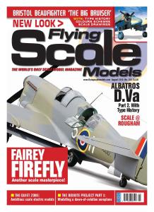
ON THE COVER Scale biplane elegance at its best. Jamie Cuff owns and flies this 1/6th scale model of the Fairey Fantome, orginally designed and built by Alan Brown. At 68” wingspan, it is O.S.91 Surpass II powered. PHOTO: Alex Whittaker
JUNE 2017 NO.211 4 CONTACT Just for starters
6
6 FULL SIZE FREE PLAN FEATURE BESSON MB 411 An unusual floatplane designed by Peter Rake
12 SCALE AEROTOWING PART 2
With the mechanical requirements dealt with, let’s get to grips with the tow technique
18 INDOOR R/C SCALE NATIONALS Best in indoor scale at R.A.F. Shawbury
22 SUBJECTS FOR SCALE handley page hampden
A product of the RAF’s ‘expansion programe’ commenced in the early 1930s, the Hampden was one of a new breed of ‘heavies’
26 A WARBIRD TO REMEMBER
Peter Anderson’s Handley Page Hampden was built more than twenty years ago, yet even now represents the very best of aspirational scale modelling and achievement
32 HAMPDEN FLYING COLOURS
Warpaint carried by Bomber Command Squadrons
26
34 HAMPDEN SCALE DRAWING 1:70 scale three-views
36 SCALE SOARING
Chris Williams reviews some successful finishing and colour matching techniques he has used
40 master models Fairey FANTOME
Alex Whittaker admires Jamie Cuff's beautifully constructed later 1930s biplane,a prospective warbird that never was!
44 FANTOME TYPE HISTORY
For purity and elegance of shape, the Fairey Fantome could be regarded as the most attractive biplane fighter of all
48 FANTOME SCALE DRAWING 1:40 scale three-views
50 TECHNO SCALE
Web sites review for scale modellers
52 SWARMS 2017
40
Scale action in Australia
58 BIPLANES my way PART 5
Off to the flying field - at last, with Martin Fardell
62 QUIET ZONE www.flyingscalemodels.com
More on the building and operating the Besson MB 411 this month’s full size free plan feature.
JUNE 2017 FLYING SCALE MODELS 3
CONTACT JUNE 17 Tony OK.QXT
27/4/17
12:29
Editor: Tony Dowdeswell Publisher: Alan Harman Design: Peter Hutchinson Website: Webteam Advertising Manager: Sean Leslie Admin Manager: Hannah McLaurie Office Manager: Paula Gray FLYING SCALE MODELS is published monthly by Doolittle Media, Doolittle Mill, Doolittle Lane, Totternhoe, Beds, LU6 1QX. Reproduction in part or whole of any text, photograph or illustration without written permission from the publisher is strictly prohibited. While due care is taken to ensure the contents of Flying Scale Models is accurate, the publishers and printers cannot accept liability for errors and omissions. Advertisements are accepted for publication in FLYING SCALE MODELS only upon Doolittle Media’s standard terms of acceptance of advertising, copies of which are available from the advertising sales department of FLYING SCALE MODELS. EDITORIAL ADVERTISEMENT & CIRCULATION: Doolittle Mill, Doolittle Lane, Totternhoe, Beds, LU6 1QX. Tel. 01525 222573 Fax. 01525 222574. Email:
[email protected] CIRCULATION TRADE ENQUIRIES: Seymour Distribution, 2 East Poultry Avenue, London, EC1A 9PT 020 7429 4000. NEWSTRADE: Select Publisher Services, 3 East Avenue, Bournemouth. BH3 7BW. 01202 586848 Email:
[email protected] SUBSCRIPTIONS: Doolittle Mill, Doolittle Lane, Totternhoe, Beds, LU6 1QX. Tel. 01525 222573. Fax. 01525 222574. PRINTING: Henry Stone Ltd., Oxfordshire (c) Copyright Flying Scale Models 2017 Doolittle Media. The paper used on this title is from sustainable forestry
4 FLYING SCALE MODELS JUNE 2017
Page 2
CONTACT ere’s a question. What actually qualifies as a Warbird? Is it an aircraft type that has equipped an Air Arm during a formal military conflict? Is it one that served only at a time of peace, but was nevertheless a fully armed combat aircraft that carried the National insignia and markings of a country’s air force? Does an aircraft type designed to a military specification formally issued by a national air arm, that carried military markings at prototype and test stage but never went into service, qualify? This issue of FSM deals with examples of each. The Handley Page Hampden early WW2 bomber, our Subject for Scale in this issue, is the clearest qualifier - it served in many Squadrons of RAF Bomber Command, and crew members earned two Victoria Crosses - UK’s foremost military accolade. Obscure by any standards and with only two examples that went into service, the Besson MB 411 floatplane, was designed to be carried in, and operate from, an ocean-going submarine ... and it did, prior to WW2, but also in 1940. It features as the subject for this month’s full size free plan. Finally, there’s our Master Models piece which this month features the late 1930s Fairey Fantome biplane fighter. It never went beyond prototype form, but one fully armed example was flight tested by the Royal Air Force, carrying RAF insignia and in addition, two further Fantomes served with Republican forces during the Spanish Civil War, having got there via the Soviet Union. Well, what’s your answer?
H
SCANDINAVIAN BALTIC MASTERS
Graham Kennedy writes to say that, since the cessation of the European F4 Scale Championships, last held in Norway in 2009, there has been a void in the ‘odd’ years between the World Scale Championship events. A worthy alternative this year will be the Scandinavian Baltic Scale Masters, which is an open competition for scale models competing in F4C, F4G, F4H. The Norwegian Scale Team, Helsingborg Model Aircraft Club and Helsingborg Flying Club will be holding the inaugural Scandinavian Baltic Masters Scale Event to be held from 18-20 August 2017 at Helsingborg MFK Airfield, Norway. Helsingborg has all the attributes that are required for a Scale meeting of this size - a great airfield, facilities for camping on site and proximity to a main city, which enanbles easy travel from most of Europe and a superb team has been put together to run the event, along with some of the best judges in this part of Europe. Registered participants for the three classes have been much higher than anticipated and include entries from the Scandinavian countries, from France, Germany, Netherlands, Romania and even Australia. The entry list is now closed, but spectators from everywhere will be very welcome. All who are interested may find further information at http://www.scale-master.se Graham will be covering the event for Flying Scale Models.
JOHN O’DONNELL
One of the aeromodelling’s true achievers was lost to our hobby when John O’Donnell died as a result of a tragic accident, at home, on April 19th. Although John’s achievements in compeition aeromodelling were well outside the Scale side of our hobby, his was a universally recognised name among all aeromodellers for well over half a century. Affable, friendly and willing to help, he will always be ascociated with the free flight rubber power competition categories, of which he was an undoubted master. His competition models often appeared slightly untidy and patched, but this was a visual deception that masked a well built, accurate and finely trimmed airframe, fully fit for purpose and well in tune with John’s down-to-earth casual character. He has been so well known, that all who’ve known him will have their own endearing memories of him; this Editor’s abiding memory will always be of John, during one of the annual National Championships in the late 1960s or early ‘70s, ambling nonchalantly up the main runway toward the take-off positions of the R/C Aerobatics event, bicycle clips in place and wheeling his bike (for free flight downwind retrieval). The R/C Contest Director was unamused to say the least, but it will always by this Editor’s most fond memory of J.O’D.
BELAIR MAR 17.indd 1
25/01/2017 12:23
BESSON 411 FREE PLAN.qxd
26/4/17
16:48
Page 2
FULL SIZE FREE PLAN FEATURE
BESSON 411
An unusual floatplane designed by Peter Rake with the prototype model built and flown by Mat Hourston. The beautiful outdoor photos are thanks to Warren Ormsby
W
hen I was first approached to design a floatplane (or flying boat), I was very reluctant. Having nowhere, personally, to operate a rise-off-water (RoW) model, it was something I was totally unfamiliar with and had no idea what was required to make one work. However, while looking for something else, I stumbled across plans for a rubber powered floatplane that ticked all the right boxes to get my interest - not that this discovery helped at all as far as the mechanics of the thing were concerned. Yes, I could certainly design a model that would fly, but getting the float details right so that it would actually work as a floatplane, was an entirely different matter; more on that, however, as the saga continues.
THE AIRCRAFT As you can see, the Besson 411 is a pretty
utilitarian looking aircraft and a compact, one at that - the reason being that the full size was intended for use (and storage) aboard a submarine of all things; the ingenious ideas these French come up with from time to time! As you can imagine, space on board a submarine is more than just a little restricted, so the aircraft appears to have precisely what is essential and no more. However, because it needed to be partially dismantled after each use there are rather more struts than you’d expect to see on a mid-1930s monoplane.
THE MODEL Having discovered the type, and gained approval from the person (not Mat) who first requested something to fly off water, I settled on what is roughly 1:12 scale, a nice size to be relatively quick to build and, by happy coincidence, one that fits nicely into free plan format. Having decided to stick with
With a hop and a skip the little Besson is safely down again.
approximately scale float design (after all, if it worked for the full size machine it should work on a model) it was just a case of deciding what angle the main float should be set at, relative to the datum of the model. As you can tell, I’m way out of my comfort zone here. Not only does this aircraft qualify a WW2 warbird (just about), it’s also a floating warbird. Way, way out of my comfort zone! Now it would be very nice to be able to report that everything went swimmingly as a result of this first build. Nice, but somewhat less than truthful. The original builder reported that the model was a real handful in the air and wasn’t particularly well behaved on the water. However, having seen a video of this model in action I very much suspect that balance was marginal and it appeared to be hauled into the air rather abruptly, probably before it had not fully reached flying speed. As a result, the model suffered some
BESSON 411 FREE PLAN.qxd
26/4/17
16:48
Page 3
minor damage, which the builder said he’d fix and then try again. That, unfortunately was where he promptly fell off the face of the earth and not another word was heard from him about the poor little Besson first prototype model. Four years or so passed, with the design languishing in the depths of my computer. Another appeal for prototype builders brought a response from Mat Ormsby and the result is the model you see here. Obviously Mat has a bit more experience with this style of model because the first thing he changed was the angle at which the main centreline float sits. This went from a pronounced negative angle to pretty much parallel with the datum. Anti-spray strakes were added, to prevent water getting into the motor and the build progressed apace. With the balance point moved slightly further forward (the float appears to have some aerodynamic affect on the way the model flies), the model has now become a nice flying little aircraft that handles well on the water. Achieving that was a bit of a trial-and-error process, although there doesn’t actually appear to have been much error involved. Mat made the changes and the model behaved as was intended. All the changes he made are now incorporated into the plan, so you should start out with a problem-free model.
CONSTRUCTION
Fuselage construction begins in the usual fashion. note the saw cuts inside the nose areas.
CONSTRUCTION Although there is nothing particularly difficult involved in building this model there are lots of little points of interest. Whilst I could make this a very long construction article, I feel it would be better if I restrict this to the basic build, but include as many of those interesting points as possible in this month’s Quiet Zone that appears elsewhere in the magazine. That way I can go into much greater depth on some of the points Mat made about both the build and how the model performs. That being the case, let’s get down to getting our little Besson 411 built.
FUSELAGE The fuselage construction is all very traditional. Begin by building two side frames over the plan and then score a series of shallow saw cuts on the inside of the sheet sides forward of F2. This will allow the fairly sharp curves where the sides pull in and glue into F1. Be sure that these scorings are positioned uniformly across both fuselage sides, so that the side pinch in symetically. First, however, we need to mark the former positions onto the sides and get the basic box structure assembled. Glue doublers D1 to the inside of each fuselage frame and then assemble formers F2, the radio tray and F3. Don’t glue the cross piece into F2 until after this assembly or you’ll have trouble getting the radio tray into place. Once this assembly is dry, and you’ve checked that your servos actually fit into the openings, join the two side frames onto the former/radio tray assembly. Now you can pull in the nose, gluing the sides to the radio tray, and fit F1. You’ll probably have to bevel the inner face of the tabs that fit into F1, otherwise they won’t go in easily. Fit and shape the upper and lower nose blocks, pull in and join the tail and fit the cross braces and part TS. Now it’s just a case of fitting the cable exit tubes and balsa fill pieces to complete the basic fuselage assembly. Precisely how you go about the hatch will largely depend on whether you actually intend to fly off water. If you do I would suggest closing off the openings in H2 with the cross grain
Although Mat procured a proper cowl any suitable bottle could be used. The details are nothing more technical that shaped and sealed balsa.
As close as we get to a naked model shot but it does reveal those blue painted areas mentioned in the text.
Once the tail is pulled together and cross braces fitted it starts to look more like a fuselage’.
Fuselage sides joined using a couple of formers and the radio tray.
JUNE 2017 FLYING SCALE MODELS 7
BESSON 411 FREE PLAN.qxd
26/4/17
16:48
Page 4
CONSTRUCTION
Here you see the extra keel piece Mat added to the main float in order to provide more gluing area for attaching the skins.
sheet shown on the plan. If not, you may prefer to leave them open so you can have a bit of depth to the cockpit openings. The cross grain sheeting should still be fitted, but in this case it also will have the openings cut into it. This sheeting helps stiffen the hatch, so don’t be tempted to omit it. This is particularly true if flying off water. At some point you are going to get that hatch damp and dampness will cause the ply/balsa laminations to curl. The cross grain sheet should help prevent that happening. Mat procured a vac formed cowl for his model (a 3” cowl is also available from ParkFlyer Plastics www.parflyerplastics.com), but there are many plastic containers that will work just
as well if you don’t mind being seen measuring pots in your local shops. The blisters are no more than pieces of balsa glued in place and sanded to a slightly rounded section.
FLOATS The main, centreline float is built inverted over components FLT. Mark the former positions onto FLT, glue the doublers to FLS and start gluing bits together. Mat changed the way in which his float is fitted, but that was a personal choice thing. Just as shown on the drawings works just fine and is amply strong enough. One thing Mat did alter was the curve on the front formers. He had trouble
Cruising by at low level the Besson is an attractive but unusual model.
8 FLYING SCALE MODELS JUNE 2017
Wings joined to centre section prior to adding the last few ribs and top surface sheeting.
getting the 1/16” balsa skin to conform to the double curvature, so he flattened the chines slightly. I suppose much depends on the stiffness of the sheet being used, but it’s something you might want to consider if you are experiencing the same problem. The one thing you absolutely must ensure is that the float is fully sealed. A float that leaks not only isn’t going to last long but will do nothing for the way the model flies. To make sure of this, Mat skinned his float(s) with 18 gsm glass cloth and further reinforced the forward keel of the main float with a strip of 48 gsm cloth. The tip floats were made from hot wire cut foam; two halves for each float glued together and the whole glassed for durability.
BESSON 411 FREE PLAN.qxd
26/4/17
16:48
Page 5
TAIL SURFACES To keep these parts really simple, and because the top elevator cable actually passes through the tailplane, I’ve made them from nothing more technical than cut pieces of 1/8” balsa sheet. I’m quite sure that if you need me to tell you how to assemble them we will have lost you long before now, so I won’t bother. The lightening holes shown in the fin parts are totally optional so I’ll leave you to decide if you think it’s worth the effort to cut them. Needless to say (but I will anyway), if you want to build up the tail surfaces, to save weight at the rear end of the model, that is a perfectly viable alternative. Just don’t make them too light or you may encounter warping issues during covering.
WINGS Before starting any construction, work out how you intend to install the servo extension leads and build them into the centre section as you proceed. It isn’t funny to find yourself with a fully sheeted c/s and no way to install servo leads. Starting with the easy part, let’s get the centre section built. Glue the dihedral braces B1 and B2 to their respective spar pieces and allow to dry. Now pin down the spars, leading edge and TE1 over the plan and glue in place the ribs R1 and R2, ensuring all three ribs are perfectly upright. Glue in the scrap pieces that form the strut sockets (float mounting struts) and fill in the entire lower surface with 1/16” balsa. Allow to dry completely before adding the upper surface sheeting. This is best fitted while the centre section is still pinned down to avoid any risk of distortion as the sheet is applied. Moving onto the wing panels, begin by pinning down the leading edge spars and trailing edge pieces over the plan. Glue the 1/8” balsa false trailing edge (at the aileron position) to the spar and glue in all the ribs except R3. R3 will be fitted once the wing panel can be packed up for dihedral so it butts neatly against the c/s. Fit the 3/16 balsa aileron leading edge, but only glue it to rib R9. Fit the aileron ribs and 1/8” balsa horn plate. Next glue in the 1/8”x 1/4” reinforcing pieces and strut mounts flush with the lower surface of the wing. Follow these by the hardwood servo plate rails, with the rails packed up to allow the servo plate to sit flush with the lower surface. Glue in FM1 and FM2 and allow the wing to dry completely. Pack up the wing panel and glue in place R3 before joining the wings to the c/s and adding the upper surface sheeting. Trim leading and trailing edges to shape and sand overall.
COVERING AND FINISHING
CUT PARTS SET FOR THE
BESSON 411 Get straight down to construction without delay! This month’s full size free plan feature is supported by a laser-cut set of ready-to-use balsa and plywood components. This provides the parts that, otherwise, you would need to trace out onto the wood before cutting out and includes wing ribs and tips, tail centre parts, fuselage doublers, top deck,formers etc.
IT DOES NOT INCLUDE STRIP AND SHEET MATERIAL OR SHAPED WIRE PARTS
Price £55.00 plus carriage: £11.50 (UK); Europe £26.00
Order set CUT/FSM527 Shipping Note: For shipping to destinations outside the UK and Europe, you will be charged our standard flat-rate price of £49. This covers most destinations and secures your order with us. However, we will contact you accordingly with an accurate total shipping charge prior to dispatch and either issue a refund or a PayPal money request for the balance.
Visit our secure website:
www.flyingscalemodels.com to order yours
At this point I had better point out that there was some debate about the actual colour of the aircraft. While most illustrations of the full size show a pale blue overall scheme, but others appear to show it as virtually white. Personally I think that is just bad colour rendering, but it is a possibility. As you’ll see from the photos, at one point the model had blue floats, but ended up entirely white. Mat did actually get as far as spraying the doculam covered fuselage blue and very nice it looked too - right up until the first hot day, when it blistered so badly that he had no alternative but to strip the covering and start again, this time using white film covering. In retrospect, I think it looks far nicer in this colour
Mat and flying pal lend scale to the model. Much smaller than it appears in other shots, isn’t it?
Order direct from:- Doolittle Media, Doolittle Mill, Doolittle Lane, Totternhoe, Bedfordshire, LU6 1QX, UK. Tel: 01525 222573/
[email protected].
JUNE 2017 FLYING SCALE MODELS 9
BESSON 411 FREE PLAN.qxd
26/4/17
16:48
Page 6
Sitting nice and steady on the water and all set for another outing.
than it ever would have done in a blue finish. Whichever colour you opt for, please ensure all the edges are thoroughly sealed if you intend to take your model anywhere near the water. The temptation to ‘just try it once’ is too great and you won’t be at all pleased if you end up with a soggy model. When assembling the model the only struts you absolutely need are the main float struts (main float and tip floats). All others are purely cosmetic, but add so
much to the overall appearance that they are well worth the minimal effort involved.
FLYING It would be awfully nice to say that the maiden flight went off without a hitch, but that would be stretching the truth slightly. That aerodynamic effect of the float, combined with a slight warp in one wing made for a few ‘interesting’ moments for Mat. He almost got her down unscathed until a vicious clump of mud leapt out of the
Note how Mat has replaced the wood struts with reinforced, streamline aluminium.
water and took out one of the tip floats. With the balance point moved slightly forward and the warp removed the model proved itself to handle well on the water (see notes in the column) and to be a nice steady flyer. A little fast, perhaps, but nothing you won’t be able to handle if considering this model. Mat is more than happy with the end result and we can’t really ask for more than that. Thanks Mat, your efforts are much appreciated. I
BESSON 411 FREE PLAN.qxd
26/4/17
16:48
Page 7
FULL-SIZE STORY
BESSON MB.411 and Le Surcouf
M
arcel Besson was one of the much lesser known aircraft pioneers, whose involvement in pioneer aviation dates back as far of 1912 and during the early years of WW1, progressed to aircraft design and manufacture of aircraft specifically for support of naval operations. Post-WW1, in 1920, Besson designed his H3, a civilian touring type with triplane wings and boat type hull. In continuation of the involvement with marine aviation, in 1926 came the Besson MB.35 two seat, low wing twin float observation/spotter aircraft for the French Aeronavale, intended to be capable of being stowed aboard, and operated from a submarine. Two were built, but neither ever operated from a Sub. However, the French navy did not entirely lose interest in the concept and in 1932, Besson created the MB.410 by replacing the twin floats of the MB.35 with a single main float and two outrigger floats just inboard of the wingtips. The engine was cowled and fuselage streamlining was improved, but the prototype was destroyed in a fatal accident during testing. The French Navy required a spotter
aircraft for its new submarine Surcouf which, when launched in 1929 was the largest submarine in the world and would remain so for some considerable time. Its concept was one of an oceangoing ‘underwater cruiser’ - much more heavily armed than of normal size Sub and involved a crew of 100-130, about three times the number of ‘normal’ size submarines of the period and part of the concept was the provision of one reconnaissance/spotter aircraft housed in a cylindrical hangar in the rear of the Surcouf’s conning tower. The MB.411, with its single centreline main float was specifically designed for stowing in the hangar and could be fully assembled, including the fitting of the wings, in about 4 minutes at least on land, although in open sea it took up to up to 20 minutes after it was removed from its hangar. To operate, the aircraft would be lowered into the water and retrieved by a crane. In autumn of 1934, the first of two MB.411s built was sent to Brest for boarding trials on the Surcouf which then took the Besson MB.411 to the Caribbean, arriving in September 1935 for sea trials after which it was returned to the manufacturer for changes. The second MB.411 was delivered in July
The Sourcouf as it appeared in 1940, prior to ascape from Brest naval base and voyage to UK.
Besson MB 411, extracted from the Surcouf’s hangar, being assembed on the rear deck.
1938 and replaced the first in the Surcouf. During the invasion of France by the German troops on May 1940, Surcouf was in a major refitting maintenance session at Brest To avoid capture, the submarine was put to sea with maintenance not completed and un able to dive, sailing to Plymouth, UK, while surfaced. Of the two MB.411s, the second example that arrived in Plymouth, UK, was offloaded and never again put aboard, being finally destroyed in a Luftwaffe bombing attack on the port during 1941. The first MB.411 remained in France and was assigned to Fleet Squadron. I
SpecIFICATION Length: 8.25 m (27 ft in) Wingspan: 12 m (39 ft 4 in) Height: 2.85 m (9 ft 4 in) Powerplant: 1 x Salmson 9Nd radial piston, 130 kW (175 hp)
PERFORMANCE Max speed: 190 km/h (118 mph) Range: 400 km (249 miles) Service ceiling: 5,000 m (16,405 ft)
Some sources depict the MB 411 in this basic blue colour scheme.
At the time, the Sourcouf was the largest submarine in the world. The large cylindrical conning tower/hangar are clearly shown here.
JUNE 2017 FLYING SCALE MODELS 11
AEROTOWING PART 2 TONY OK
26/4/17
16:46
Page 2
SCALE TECHNIQUE
Top end of the scale: John Greenfield’s 1/2 scale Wien vintage sailplane gets a tow from a PZL Wilga 35. (PHOTO; Chris Williams)
AEROTOWING FOR PART 2: With the mechanical requirements dealt with, let’s get to grips with the tow technique
S
cale model glider flying is a branch of the modelling hobby for which there is a massive choice of full size subjects to model, right from the early wood-and-fabric days of the early glider movement, right through to the very latest super-highperformance super-slippery ‘glass ships’. In addition to specialist kits, there is also a very wide choice of types for which construction plans are available, many of them supported by cut-parts wood components sets and ‘short kits’. Sizes range from 2.5m to 5m or even 6m span, dependent upon type and the size of your pocket. Most scale designs and many glass fibre kit designs are completely suitable for aerotow operation. It’s how you put them together that matters. The most important factor with any glider design is that it has to fly straight as a die on the glide without any assistance from the pilot. There is nothing worse than trying to
control an untrimmed glider during the tow and to hold it on station behind the tug. Before you take your masterpiece anywhere near an aerotow event, go to a suitable slope soaring site and trim it out so that when your model is behind a tug, it will perform as it should. Don’t forget that when your model is being towed by a tug, the glider’s speed will be somewhat increased above its normal airspeed. In such a situation the effect of a slightly outof-trim aileron, elevator or rudder setting will be amplified. The best way to check this out can be achieved during those preliminary slope soaring test flights. Try increasing the airspeed by applying down elevator trim and observe whether there is any left or right turn tendency as the airspeed increases, that requires correction with aileron control. If there is any turning tendency to drop a wing into a turn with ailerons set at exact neutral, then there is probably some form of
12 FLYING SCALE MODELS JUNE 2017
wing warp that needs correction back in the workshop.
MASTERING THE ACTION The actual technique of aerotowing is probably one of the most difficult tasks to teach in model scale glider flying. It’s very largely a matter of ‘knack’. Most solo pilots find it very difficult for the first two or three tows, but begin to get things more or less under control by their fourth or fifth attempts. Providing the glider has been trimmed correctly, then it is a matter of small corrections being made on the tow. Learner flyers who have little experience of gliding will find that, until they become competent at general gliding, the task of aerotow piloting will be difficult. However, we all have to learn, so if you take note of the following pointers you will be in great shape to progress further. Let us assume a tug aircraft is available and running. Connected to it will be a 60-75 ft. long (18-23mtrs)
AEROTOWING PART 2 TONY OK
26/4/17
16:46
Page 3
R SCALE SAILPLANES
JUNE 2017 FLYING SCALE MODELS 13
AEROTOWING PART 2 TONY OK
26/4/17
16:46
Page 4
FIG.13.
FIG.13a.
FIG.14.
FIG.15.
14 FLYING SCALE MODELS JUNE 2017
towline with a fitting at the end to suit our particular tow release mechanism. The tug will be positioned and waiting some 20ft (6mtrs) in front of the glider, facing into wind. Switch on the radio of your glider and check the movement of all your controls. If this is satisfactory, open your towing anchor point lock mechanism and link up your short tow line hook-up line. Close the lock and check this operation by tugging you hook-up line to ensure it is safely locked. Then, before you go to the flight line, check the release operation of your hook-up line hook. More time is wasted by the malfunction of hook-ups than anything else. Both tug and glider pilots position themselves within a few metres of each other for ease of communication and remember - during the entire tow, THE TUG PILOT IN IS COMMAND. Having completed the checks, link up to the tug’s tow line and ask the tug pilot to “take up slack”. The tug will then taxi forward slowly until all the slack in the towline is taken up and the line is relatively tight. You are now almost ready to go, but you require a ‘wing-man’. He is the chap who holds one wingtip of the glider to keep it straight and level. The wing-man’s job is to ensure that when the aerotow take-of run commences, both wing tips are off the ground to give you, the glider pilot, a good start with your tow. If your ‘wingman’ is an athletic type, he may be able to move forward for a short distance as the model accelerates, steadying the wing tip as the model gathers pace and the wings begin to work, thus minimising the risk of a wing tip touching the ground or (worst of all circumstances), digging in. After all the slack in the towline is taken up, the glider pilot will do a quick check of the air space above and behind him to ensure that it is safe to proceed. If all is O.K., he will call “all-out” to the tug pilot and you are now on your way. As you start to move off, the wing man will release his hold of the wing tip and then its up to you to keep your glider straight and level with your aileron control. Beyond that “all-out” instruction, the tug pilot is THE BOSS! If, by chance, one of your wing tips should touch the ground at the start of the roll, then counteract this with opposite aileron, but GENTLY, so as to avoid snagging the opposite wing, which could very quickly develop into a very nasty situation. This operation needs quick reaction from the glider pilot. If in doubt, be ready to release the low line - so be sure you know, instinctively, where you tow lease switch is on your transmitter. If you happen to be flying a modern glass sailplane, it does help to have a monowheel fitted to the fuselage to give your wing tips just that little more ground clearance. Better still, you can fit a proper retract wheel like the full size. Acceleration of the tug on the tow is relatively quick so, providing your glider is trimmed correctly for straight and level flight, it will be off from the ground and climbing out fairly quickly. Always try to position your glider slightly above the tug on the tow, see Fig 13 and 13a. This helps the tug pilot. If your model sits below the tug, you run the risk of the towline
AEROTOWING PART 2 TONY OK
26/4/17
17:27
Page 5
interfering with the tail of the tug as it will be tending to pull the tug’s tailplane down and will thus slow the tug down. An experienced tug pilot would immediately tell you to reposition you glider relative to the tug and if there is no response from the glider pilot he may well ask you to release your glider. Finally, if there is still no response, he would release the line from the tug. As you can see, communication between tug pilot and glider pilot is all-important. Most tug pilots tend to chat away to the glider pilot if he is new to the game, giving him encouragement. When you are in the right attitude to the tug and are gaining altitude at a fair rate, but are tending to wander about quite a lot, don’t panic. You have possibly been applying aileron to keep in line with the tug, so straighten the glider out and let it centre behind the tug on her own. See Fig. 14. If your glider does tend to drift again, use a little dab of rudder only. (If you have aileron and rudder coupled, switch it out before the tow; you can switch it back on when you release). If your towline is too short, this will have
ABOVE AND BELOW: ONLY FOR THE BRAVE! Two Olympia 2b quarter-scale sailplanes on simultaneous tow at Middle Wallop. (Cliff Charlesworth designs) (PHOTO; Chris Williams)
AEROTOWING PART 2 TONY OK
26/4/17
16:46
Page 6
Ali Machinchy’s Super Decathon tows a 3rd scale Habicht at Middle Wallop. (PHOTO: Chris Williams)
Barry Cole’s Piper Cub at the County Model Flying Club towing a 1:3.5 scale Skylark 4. (PHOTO; Chris Williams)
Darren Maple and his over20 Kg PZL Wilga 35. Wilga much used in full size aero towing (PHOTO; Chris Williams).
16 FLYING SCALE MODELS JUNE 2017
the effect of making you wander from side to side due to the slipstream from the tug. As you gain further height on the tow, it is quite easy to overdo the climb and a stall on the towline is not what either you or the tug pilot wants. From where you and the tug pilot are standing, you should be seeing basically a plan view of both tug and glider because by now you should be approaching the end of the tow. If it is a calm day for your first tow, the tow will be a more extended affair because you will have to make a series of 180 degree turns to avoid the tug and the glider getting too far away from you before sufficient height is reached. See fig. 15. Great care should be taken by the tug pilot not to make these turns too steeply, otherwise the towline will go slack and a snatch or broken towline will be the result. If your glider has good lateral stability, a slight touch of opposite rudder to the direction of the tum will more often than not keep the line taut during the tum. From the glider aspect, do not apply too much aileron control during these turns; otherwise you will end up alongside the tug with a slack line. It’s a question of ‘gentle does it’ with the controls for a nice smooth tow.
PLEASE RELEASE ME When you have gained the altitude that you desire, you must inform the tug pilot that you are going to release. On no account at this point of the tow must you stick your nose down prior to release. If you do so, the glider will accelerate towards the tug, the line will go slack and upon release, the glider will fly into the towline where there is a risk of it wrapping
AEROTOWING PART 2 TONY OK
26/4/17
16:47
around your wing with disastrous results, so maintain your towing attitude and tell the tug pilot you have released after you have pressed the appropriate switch and then gently turn away from the tug a 90 degree tum. See Fig. 16. The direction of your turn should to be stated to the tug pilot prior to your release so that you don’t both turn the same way. After your first successful tow-up behind a tug, you should be pleased with yourself, but as the old saying goes ‘practise makes perfect’ so you should avail yourself for further practise.
Page 7
FIG.16.
WHAT CAN GO WRONG? During your first few tows, you will have no time to consider such things as what to do if you have a towline break or if the tug has an engine failure or loses power just after take off. Fortunately the latter does not happen very often these days, but when it does, the glider pilot must release instantly, otherwise you could be responsible for the demise one very expensive tug - and that in addition to whatever happens to your glider! If a towline breaks just after, take off, quick action from the glider pilot is required. Let us assume you are only 20ft (6mtrs) or so up when the break occurs. Providing your direction into wind is clear, then get the glider’s nose down into level flight, put the airbrakes/spoilers out and land straight ahead regardless. If you are a little higher when the break occurs, then level off and proceed to do an ‘S’ turn to bleed off height as in fig. 17. Whatever you do in this situation, don’t attempt a circuit. Nine times out of ten it won’t come off and you are made to look a right fool in the process. In an emergency such as described and especially if you are flying a large scale model, safety is paramount and for the sake of your masterpiece, don’t take risks. On most gliders, the airbrake/spoilers are operated by the throttle control and during either the tow-up or the ensuing flight, many glider pilots have, inadvertently, moved the stick and opened the brakes. I have seen this happen many times on the tow, with the result that the glider can’t keep station correctly behind the tug and the tug struggles to climb as well. (Fig.18). In a full size situation such as this, it can be very dangerous and it usually ends up with the tug giving the wave off signal. (See Fig. 19). In model form, the tug pilot would, or should, tell the glider pilot to release. If by chance, the tug pilot and the glider pilot are new to the game, then take it easy and do lots of short tows to build up your confidence. During the training stage, don’t attempt to do a circuit with a glider in tow because, when you start to do your down wind leg, things are likely to go completely out of shape. i.e. the glider catches the tug up and then all hell breaks loose. Leave this type of manoeuvre alone until you are more competent and have many hours of towing under your belt. So there you are - a few basic clues as to what this exciting part of scale glider flying is all about. I
FIG.17.
FIG.18.
FIG.19.
JUNE 2017 FLYING SCALE MODELS 17
INDOOR SCALE NATS revised Tony OK
27/4/17
10:07
Page 2
SCALE IN ACTION
BMFA RC INDOOR SCALE NATS 2016 The Belly Of The Whale Jonah Whittaker delves deep inside RAF Shawbury
I
t was a cold start, 2 degrees, but it was bright and sunny. I tootled over the border and down to RAF Shawbury. Once there, I turned left into Dawson’s Rough. Here, surrounded by the winter trees was our scale venue: an unusual but characterful old hangar, now turned into a gymnasium. An unlikely place for an BMFA R/C Scale Indoor National Comp, being windowless, utterly deadly for any flying photographs but superbly spacious for the flying.
Geodetics Inside I felt like Jonah in the belly of the
18 FLYING SCALE MODELS JUNE 2017
Big Fish. The dim light and whale-like geodetic ribs only aided this impression. The quality of light was gloomy and vaguely organic. Essentially, it was like taking pictures inside a fish tank that had not been cleaned for a few years. I had my own fun and games later when my ruinously expensive Canon flashgun started smelling like a burnt dodgem, fizzed a bit, then packed up altogether. My trusty tripod just about saved the day, but it was a damn close run thing. However, the event itself was wonderfuly friendly, welcoming and well run. Everybody pitches in and helps. There are
two Classes of Competition: “Flying Only” and “Scratch”.
Models I Saw I was knocked out by the build quality of Eric Strefford’s immaculately presented Albatros D.Va. the detail of which was complete, right down to the wood graining on the fuselage. To think that this model is of moulded foam construction makes the surface detail astounding. Eric’s indoor genius does not end there: his foamie 4x30mm EDF unit Avro Vulcan B.2 was a further exercise in technical brilliance. His flying performance in the
INDOOR SCALE NATS revised Tony OK
27/4/17
10:09
Page 3
Eric Strefford’s impressive foam AVRO Vulcan B2.
Graham Smith’s 60” span Short Scion on an overhead pass!
The busy bits of Eric Strefford’s AVRO Vulcan B2: four 30mm electric Ducted-Fan units.
Graham Smith’s ambitious electric powered Short Scion has twin geared props.
Graham Smith gives scale to his stunning scratch-built 60” Short Scion.
Chris Hodges’15” span e-Flite Boeing PT-13/17Stearman. ARTFs are entirely acceptable in ‘Flying Only’.
Beautiful D.H. Tiger Moth from Ian Pallister. First in ‘Flying Only’.
Top of the Indoor R/C Scale Master’s art: John Bowerman’s exquisite Sopwith 1 1/2 Strutter.
Scrach-Built class was Best In Class too, so our Eric really is a polymath. Another beautifully built model was Ian Pallister’s Fokker E.III Eindekker. If you looked closely, it was replete with special hand-crafted scale mouldings. Staying with the WWI theme, John Bowerman’s crisply modelled Sopwith 1 1/2 Strutter was truly superb. This was another scratch-built model on hand, built to 1/20th scale. In the Event she racked up an impressive flight score as well presenting a very good static showing. For my money, this was the best all-round effort of the comp, though John did not win. Mind you, this comment takes nothing away from Danny Fenton’s beautifully put together Piper Cub. It was special, and deserved Top Podium. Paul Hoey’s Sopwith Triplane was another exquisitely put-together scratch built model, and was only let down by a less -than-stellar flying score. By the way, in the non-competing section of the hall, undisputed scale maestro Pete Iliffe was test flying his only-just-completed Kawasaki Ki 61Hien. I do not have the necessary superlatives for this matchless
model. Pete even got in a short test flight. Also not in the comp, I spotted noted scale man Peter Fardell was test flying a very interesting model. It was a 25” span Caudron Type F. I hope to get some flying shots of this intriguing example in due course. However the Star Of The Comps for me at least, was the incredibly light, large, and astoundingly slow-flying Short Scion by Graham Smith. It cruised about with such authority. This indoor Leviathan spans a cool 60” (1524mm), but weighs just 4 3/4 ozs (around 200grams). This model is electric powered, with geared down motors and is ingeniously constructed from foam to Graham’s own method. I hope to bring you more details of this astounding flying model, and her construction, in due course.
can enter it here, and also in the ‘Scratch’class. Twelve entrants returned scores in the 2017 Flying Only event:
Flying-Only Competition In ‘Flying Only’, the focus is on scale-like indoor flying. The model itself is not marked for accuracy and realism, and can even be an ARTF. Of course, if you have scratch built your own model you
Ian Pallister Tiger Moth Andy Bowman Spacewalker Chris Hodges Aeronca Champ Nathan Strefford Spacewalker Danny Fenton Aeronca Champ Graham Smith Short Scion Ian Lever Spacewalker Liam Strefford David Yates
Tiger Moth Se5a
Eric Strefford Tiger Moth John Bowerman Spacewalker Paul Hoey Piper Supercruiser It was a busy, well-natured, comp. Chris Hodges placed 3rd with his Aeronca Champ. Andy Bowman was Second with his Spacewalker. The Winner was Ian Pallister with his Tiger Moth.
The Strefford Boys Unusually - and most encouragingly - we
JUNE 2017 FLYING SCALE MODELS 19
INDOOR SCALE NATS revised Tony OK
27/4/17
10:12
Page 4
Nifty SKYRC multi-charger for indoor electric models. Ideal for Parkzone gear.
Danny Fenton was flying this attractive and different-looking new Taranis transmitter.
Ian Pallister’s beautifully hand-crafted Fokker Eindekker.
There was even a classic scale kit stall!
Industrious Ian Lever (SAMite of Note) and some of his indoor fleet.
had two Juniors competing in the FlyingOnly class. Brothers Nathan and Liam Strefford were vying with their grandfather Eric for flying honours. In the outcome, Grandad Strefford was comfortably beaten by both lads. Nathan placed 4th in Flying Only with his Spacewalker, and
Liam placed 8th with his Tiger Moth. Both well taught, no doubt.
that air manoeuvres are also marked, as well as the Static judging. The model aircraft has to be the product of your own scratch-built endeavour. Marks are deducted in the Static Judging if you used a few commercial items like canopies, wheels, and props. Four
Scratch Competition For this competition class you must sign a Builder Of The Model (BOM) form. It is very similar to the Outdoor Scale classes, in
Eric Strefford’s Albatros, immaculately constructed from moulded foam. The wood grained panel detail is especially impressive.
Scale man Peter Fardell with yet another unusual prototype: 25” span Caudron Type F.
20 FLYING SCALE MODELS JUNE 2017
INDOOR SCALE NATS revised Tony OK
27/4/17
10:13
Page 5
Sneak preview of Scale Maestro Peter Iliffe’s latest masterpiece: Kawasaki Ki 61 Hien, is just about perfect. It has been test flown, too.
Paul Hoey’s excellent scratch-built Sopwith Triplane, built to 1:14 scale
entrants returned scores in this event: Danny Fenton John Bowerman Paul Hoey Eric Strefford
Piper J-3 Cub Sopwith Strutter Sopwith Triplane AVRO Vulcan B.2
This was a tense comp since the final score can be tipped by either a very good flight, or a very well presented model. For example, Eric Strefford placed
Fourth, but had the best flight score of the day. Danny Fenton had a very good static score, but his flying score was third in its class, the ideal combination for this class being an accurate, totally scratch built model flown with impeccable skill! The final order was Paul Hoey with his Sopwith Triplane in 3rd place; John Bowerman with his Sopwith 1 1/2 Strutter in 2nd. Danny Fenton with his Piper Cub PA18-95 won.
Acknowledgements Especial thanks to John Minchell and his Team for organising the day. We were also very grateful to Paul Rich for his sterling work on the computer scoring system. No scale comp is worth its salt without knowledgeable and conscientious Judges. We had that in spades with Chris Allen, Doug Hunt, Ian Pallister, and David Whitehouse. They handled the intricacies of Scale Judging with aplomb. I
Inside the belly of the whale - all geodetic ribs and military history.
HAMPDEN TYPE HISTORY.qxd
26/4/17
16:44
Page 2
SUBJECTS FOR SCALE
Hamden Mk.1. The pilot obviously preferred the cockpit canopy to be slid back. The slenderness of the ’pencil’ rear fuselage and narrowness of the main fuselage are well illustrated here.
HANDLEY PAGE A product of the RAF’s ‘expansion programe’ commenced in the early 1930s, the Hampden w
‘
Flying Suitcase’, ‘Panhandle’ and ‘Flying Tadpole’ were all unofficial names prompted by the distinctive shape of the Handley Page HP 51 that was one of three outcomes of a 1932 Air Ministry Specification, the others being the Vickers Armstrong Wellington and Armstrong Whitworth Whitley - a trio of big (for their time) twin-engined bombers that bore the brunt of R.A.F. Bomber Command’s early offensive during W.W.2. Unlike its contemporaries the Wellington and Whitley, it lay between those and the Bristol Blenheim in what was designated a ‘high performance’ category of its own, at a time during the pre-WW2 time of the RAF’s ‘expansion program’ when the British Air Ministry was feeling its way with bombers and was torn between taking a large load far and a smaller load quickly. The Hampden represented a compromise.
22 FLYING SCALE MODELS JUNE 2017
The original specification, B.9/32 (from which the Wellington also stemmed), was issued in mid-1932 and called for a twinengined day bomber of appreciably higher performance than any previously envisaged. The prototype Handley Page B.9/32 bomber (company designation H.P.52), eventually appeared in 1936 and was powered by two Bristol Pegasus P.E.5S(a) nine-cylinder radial engines and flew for the first time on 21st June 1936. As first flown, the prototype featured a rather more angular shape than what became the production Hamden; the aircraft’s nose had a square cut, birdcage-like appearance and the dorsal and ventral gun positions were covered by similarly angular transparencies and it was in that format that it was first shown to the public in June that year, exhibited in the New Types Park at the annual Hendon Air Pageant.
So successful were the initial flight trials that in August 1936, within about six weeks of its first flight, the Air Ministry issued an initial production order for 180 machines to specification B.30/36, while at the same time ordering a further 100 machines to be powered by the 24-cylinder H-type Napier Dagger air-cooled engine, the production of the latter being allocated to Short Brothers & Harland at Belfast. Revision of the shape of the aircraft came with the second prototype in 1937, the ventral gun position now more rounded, almost in ‘production’ form and to complete the ‘facelift’ the nose too had undergone slight modification. The production prototype H.P.52, flew in May 1938, powered by 1,000-h.p. Pegasus XVIII engines with two-speed superchargers. It differed from the two original prototypes in several other respects: the nose was now a compound-curved Perspex moulding
HAMPDEN TYPE HISTORY.qxd
26/4/17
16:44
Page 3
E HAMPDEN n was one of a new breed of ‘heavies’ incorporating an optically-flat bomb aiming panel and the dorsal and ventral gun positions were also revised, the former having a roomier, semi-circular cupola hinged to allow it to be pushed back over the gunner’s head. Another leading feature of the Hampden was a highly tapered, low-drag wing incorporating the most advanced (then) slot equipment. This enabled its high top speed of 265 m.p.h. to be achieved without sacrifice of landing speed, which was only 73 m.p.h. In consequence, under active service conditions, the Hampden proved easy to handle. Its speed and 980 ft./min. initial rate of climb were greatly in advance of its contemporaries.
INTO SERVICE No. 49 Squadron, based at RAF Scampton (then flying Hawker Hind two-seat biplanes) was the first to receive production
Hampdens, their first on 20th September 1938, a further eight trickling in by November and by the end of the year both Nos. 49 and 83 were fully equipped, and another (No. 50) had begun to re-equip, bringing the R.A.F. Hampden in-service complement on to total of 36. Production of Hampdens soon gathered further pace with orders under sub-contract by English Electric Co. at Preston, this company being awarded its initial contract for seventy-five aircraft, while in Canada, Canadian Associated Aircraft Ltd was formed, to handle an initial order for eighty Hampdens for the R.A.F. On 3rd September 1939,when Britain formerly declared war on Germany, ten squadrons of Bomber Command were equipped with Hampdens. Early operations were confined to armed reconnaissance against German naval units and by the end of 1939 No. 5 Group Bomber Command
had flown twenty-one such missions in daylight. On 29th September eleven Hampdens from No. 144 Squadron were detailed to search part of the Heligoland Bight to within sight of the German coast. The Hampdens operated in two formations, one of five and the other of six aircraft. The formation of five was completely destroyed by enemy fighters from the North Frisian Islands so that from 18th December, Bomber Command tacitly abandoned the belief that Hampdens and Wellingtons could operate by daylight in the face of German fighter opposition. Thenceforth, it despatched them only under cover of darkness. Early in 1940 Hampdens began to take a share in dropping propaganda leaflets; operations popularly known as ‘bumph raids’ and by the end of that year 123 night sorties had been flown with leaflets, at a cost of one aircraft missing.
JUNE 2017 FLYING SCALE MODELS 23
HAMPDEN TYPE HISTORY.qxd
26/4/17
16:44
Page 4
Achtung, Minen!
Prototype H.P.52 on final approach, with wing flaps fully extended. The extreme ‘boxey’ shape prior to subsequent refinement is clear here.
During the winter of 1939-40, Hampdens were adapted to carry magnetic mines, the first of these weapons being laid by nightflying Hampdens of Nos. 44, 49, 50, 61 and 144 Squadrons in enemy waters on the night of 13/14th April 1940, a few days after the German invasion of Norway. The aim of the R.A.F.’s minelaying campaign, a joint Bomber Command/Coastal Command operation, was the sowing of mines in areas unapproachable by British ships. Between April 1940 and the end of that year 1,209 minelaying sorties were flown by No. 5 Group’s Hampdens, 703 mines were laid, and twenty-one aircraft went missing on these operations - a casualty rate of less than 1·9 per cent of sorties, which was considered very satisfactory for work that, although undoubtedly less dangerous than operating over Germany, was by no means easy. During the Norwegian campaign from April until June 1940, Hampdens were again pressed into service as day bombers, again quickly proving to be highly vulnerable for any determined enemy fighters. The plain facts were, of course, that the Hampden was still a very feebly armed aircraft with a single rearward facing upper gun and a single one underneath, manned by a gunner in a hopelessly cramped position, together with two guns firing forward, one of which, being fixed, was completely useless. Drastic action following the losses on daylight raids in the spring of 1940 resulted in the Hampden’s movable rear facing armament being doubled.
TO GERMANY IN ANGER
Early example of Hamden Mk.1 here reveals the single machine guns position at the upper and lower rear gunner stations. Not exactly devastating defensive armament!
On the night of 19/20th March 1940, Hampdens took part in the first deliberate bombing over German soil with an attack on the enemy’s hangars and slipways for magnetic minelaying seaplanes at Hornum on the Island of Sylt. This was in the nature of a reprisal for an enemy raid on the Navy’s anchorage at Scapa Flow three days earlier. Following the German break-out in the Low Countries in April, Hampdens attacked targets in support of the Allied land forces. They made history again on the night of 11/12th May when they took part in the first big raid on the German mainland, two days after the Luftwaffe had dropped bombs on the British mainland. Their objective was railways at Munchen Gladbach, while later
Hampdens in close formation. The defensive armament for both gunner stations are either stowed or not fitted on the aircraft in the foreground.
A clear illustration of the slender rear fuselage. The wing leading edge slots here are extended and the flaps can be seen at maximum deployment.
24 FLYING SCALE MODELS JUNE 2017
HAMPDEN TYPE HISTORY.qxd
26/4/17
16:45
Page 5
An early Hamden Mk.1 of No.144 Squadron, Royal Air Force, in flight during May 1939.
Ready for action! The full crew of a Hamden was five members. Here the Air Gunners are carrying twin- Vickers ‘K’ guns.
DOING THE ROUNDS! Trio of No. 106 Squadron Hampdens, tightly formated during April 1940. One of these forms the five-view colour scheme plate elsewhere ion this issue.
that summer they were flung into battle against the German barges concentrated in the English Channel and North Sea ports for the invasion of Britain. On the night of 25/26th August 1940, Hampdens took part (with WhitIeys) in the R.A.F.’s first bombing raid on Berlin. Among the aircraft that claimed to have bombed the ‘Big City’ were Hampdens from Nos. 44, 49, 50, 61 and 83 Squadrons. Hampdens also took part in each of the three ‘1,000- bomber’ raids of mid-1942 although by then their days as operational night bombers were numbered, and on 14/15th September came the last Hamden Bomber Command sorties, when aircraft of No. 408 (Goose) Squadron, R.C.A.F., attacked WilheImshaven.
HAMPDEN VICTORIA CROSSES During the summer of 1940 two V.C.s were awarded for operations in Hampdens. The first was for Flight Lieutenant R. A. B. Learoyd, who became the first Bomber Command pilot to receive the decoration. Learoyd, of No. 49 Squadron, was flying one of a force of five Hampdens from Nos. 49 and 83 Squadrons, that attacked an aqueduct on the Dortmund-Ems Canal with delayedaction bombs on the night of 12/13th August. The second V.C. went to Sergeant John Hannah, wireless operator/air gunner in a Hampden of No. 83 Squadron, for extinguishing a fire in the aircraft following an attack on invasion barges at Antwerp on the night of 15/16th September. No. 83 Squadron was the first Bomber Command unit to drop a 2,OOO-lb. bomb on the enemy. The 2,OOO-pounder (semiarmour piercing) was dropped by a Hampden in a raid against the German battle cruiser Scharnhorst at Kiel on 1st/2nd July 1940, captained by Flying Officer (as he
A Hamden of No.44 (Rhodesia) Squadron shortly to receive one of the 2,000 lb. ‘high-capacity’ bombs from the trailer train. Known as ‘land mines’ these weapons had parachutes in lieu of tail fins, but aiming accuracy was poor and the parachute was eventually replace by metal tail fins.
then was) Guy Gibson (later to win the V.C. while commanding No. 617 Squadron).
MAKING UP THE NUMBERS Production of the Hampden by the parent company ceased in July 1940, with the 500th aircraft, but prior to that, deliveries from English Electric’s assembly line had begun. In all, English Electric built 770 Hampdens, the last leaving the line on 15th March 1942. The first Canadian-built Hampden, flew on 9th August 1940, and by the following October, production had reached a rate of fifteen per month. These aircraft were ferried to the United Kingdom, the total Hampden production by Canadian Associated Aircraft reaching 160 machines when the last was delivered at the end of 1941. At one time it was proposed that Canadian-built Hampdens be fitted with 1,100-h.p. Wright Cyclone radials, but this scheme did not proceed.
TORPEDO BOMBER Following experiments with Hampdens at the Torpedo Development Unit, Gosport, two hamden squadrons, were transferred from Bomber Command to Coastal Command in April 1941 for employment in the Torpedo Bombing role. Later that year detachments from each Command went to Russian and, operating from Avenge near Mermansk, helped guard the north Russian convoys. The outward journey was extremely hazardous and one Hamden was shot down by a Russian fighter while coming in over a prohibited area. Of those deployed, a total of six were lost en-route over Norway and Sweden. Hampdens continued in service as torpedo-bombers until 1943 with two further Coastal Command squadrons, eventually
ceasing these operations in at the end of 1943. The Hampden T.B. Mk. I, as the torpedo-bombing variant was eventually designated, differed from the standard Hampden B. Mk. I in having a slightly deeper bomb bay to accommodate an 18 inch torpedo internally and in addition to the torpedo, it could carry two 500-lb. bombs on racks under the wings.
SOMETHING OF A PILOT’S AEROPLANE Whatever its operational shortcomings, the Hampden was reputed to be one of the nicer aircraft (of its class and era) in the air. On the downside however there was certainly little room in the one-place cockpit of the aircraft that had a fuselage width of just 3 ft. and it must have been very uncomfortable for those who had to stay airborne in it for many operational hours. Nor were the various control and instrumentation items any too accessible to the pilot until he had become accustomed to the layout. In contrast to all this, the pilot could see well from his cockpit seat and he always felt part and parcel of the machine. Although it was then classified as a ‘heavy’, it was really extraordinarily nimble on the controls for is size, and when making steep turns, the turning view from wing-tip to wing-tip was excellent. One perhaps disconcerting feature of the airframe, for anyone appropriately positioned in the rear of the aircraft was the view looking rearward from which could be viewed the continuous twitchings of the tail surfaces at the end of the rear fuselage ‘boom’. This always looked as if it ought, ultimately, to break off! Rear gunners on the other hand used to say that it was nice to have the ‘pencil’ rear fuselage because there was so much less for the flak to hit! I
JUNE 2017 FLYING SCALE MODELS 25
WARBIRD TO REMEMBER Tony ok
26/4/17
16:30
Page 2
SCALE ACHIEVEMENT
A WARBIRD TO PETER ANDERSON’S HANDLEY PAGE HAMPDEN DID THE ROUNDS OF NATIONAL SCALE COMPETITIONS MORE THAN TWENTY YEARS A REPRESENTS THE VERY BEST OF ASPIRATIONAL SCALE MODELLING AND ACHIEVEMENT
T
his is no new model. Peter Anderson began construction of his Handley Page Hampden more than twenty years ago, but that detracts nothing from the interest value of this model which, then and now, represents true dedication in the pursuit of maximum authenticity in a truly practical, eminently flyable competition replica. The Handley Page Hampden was one of the trio of R.A.F. first-generation monoplane multi engine bombers designed to meet a pre-WW2 Air Ministry requirement at a time when the size and effectiveness of the RAF had been cut to the bone during worldwide depression years that eventually led to the realisation of the international security threat and subsequent ‘expansion program’. The other two aircraft types were the Armstrong Whitworth Whitley and the Vickers Wellington, with which RAF Bomber Command
commenced their Bombing offensive during the opening years of WW2 before the arrival in service of the true ‘heavies’, the Short Stirling, Handley Page Halifax and Avro Lancaster. In comparison to those big four engine machines, the Hampden, today, looks rather quaint, but it has a certain ‘presence’ about it that makes it a good subject for multi engine R/C scale. There is a good long tail moment and the engines are set close in to the fuselage centreline, while at the scale that Peter Anderson chose for his replica, there’s also plenty of wing area, even with those sharply tapered wings.
26 FLYING SCALE MODELS JUNE 2017
WARBIRD TO REMEMBER Tony ok
26/4/17
16:30
Page 3
O REMEMBER
ARS AGO, YET EVEN NOW
JUNE 2017 FLYING SCALE MODELS 27
WARBIRD TO REMEMBER Tony ok
26/4/17
16:31
Page 4
1
2
As the detail pictures here show, Peter’s model represents a glorious celebration of totally ‘conventional’ balsa/ply airframe construction technique - there’s not so much as a single granule of expanded polystyrene foam in this one! An interesting feature of the wing construction is the ribs, each of which is made up of an outline strip and diagonal braces, each meticulously reinforced with plywood gussets. This is true dedication and true scale, replicating the full size. Quite apart from the objective of
3
scale authenticity, it affords good access through the wing panels for all the cable runs to servos and for the air lines to the retract system. Any really accurate scale model starts with good, accurate reference material and, if at all possible, a full size example from which to glean as much detail as possible. Never one of the ‘glamour’ Warbirds of WW2, the Hampden simply faded from the RAF scene as more powerful and more effective aircraft types replaced it in front-line service. Unsurprisingly therefore there is
1: The basic airframe, fully assembled. Additions required are rear fuselage planking, cockpit and rear crew position canopies, plus nose section glazing. The latter, quite a challenge. 2: Baisc wind strycture. Note the wing rib construction and the two pedestal type support jigs for working on the structure after lefting from the build-board. 3: Servo and drive link to the wing flap. 4: Bare lower fuselage framework. 5: Tailcone and rear fuselage boom, latter before surface skinning. 6: Fuselage nose section, showing the delicate framework for the glazed forward section. 7: Main undercarriage drice ram. 8: Drive ram for the retracting ntailwheel. Note also the rudder control bellcrank. 9 -12: The main undercarriage machanism faithfully replicates the full size. 13: Engine nacelle firewall and metal engine mount. 14: Nacelle mounted throttle servo. 15 & 16: Fully finished engine nacelles.
5
4
28 FLYING SCALE MODELS JUNE 2017
6
WARBIRD TO REMEMBER Tony ok
26/4/17
16:32
Page 5
7
8
9
10
11
12
no complete example of the Hampden anywhere, not when Peter designed and built his model - and not even now. But there were two restoration projects to hand, from which Peter was able to obtain much useful information. One of those was a wreck recovered from
Norway by the East Kirby Heritage Museum, which has been destined for action in northern Russia, but was lost en route. Access was also obtained to parts of another Hampden, also recovered from Norway and, at the time, held in the RAF Museum’s Store at Cardington,
13
14
15
16
Bedfordshire. Modelled to 1/7th scale, to produce a wingspan of 118.5” (2997mm), the model was four years in the making, commenced back in 1991, first flown in 1995 and thereafter became a ‘regular’ at major R/C scale competition events,
JUNE 2017 FLYING SCALE MODELS 29
WARBIRD TO REMEMBER Tony ok
26/4/17
16:33
Page 6
17 18
where it performed regularly and reliably, suffering a few knocks including one when a motor cut, presenting the pilot with a serious asymmetric power situation. Much true modeller’s skill went into this impressive model, for example Peter fabricated a complete air-driven control system for both the retracting undercarriage, including the full retractable tail wheel and the operating bomb doors, with his own home-built actuating rams, air valve system and pressure air reservoir, the latter based simply on an aerosol can. Peter also engineered and machined the retracting undercarriage unit, all exact true scale with true-scale retract sequence, the mains tucking away into the engine nacelles, closing the doors behind them. Weighing in at 38 lbs (17.3 kg), power came from two Laser 150
19
20
30 FLYING SCALE MODELS JUNE 2017
21
22
four stroke engines turning Graupner 16” x 8” prop. With a wingspan of 119” (3023mm), the model represents a fair size lump, not easily transported around in a For Escort estate car, so the Hampden was designed and built from the outset to break down into five basic components comprising wing centre section with engine nacelles and retracts, wing outer panels, plus front and rear fuselage sections all of which just about fitted into the car space available. Fuselage sub-assemblies were built to slot into the wing section using the mainspar as guides, bit full airframe assembly requires almost an hour - although slightly less for breakdown - which was probably rather welcome at the end of a day’s competition, particularly with the prospect of a long drive home! I
WARBIRD TO REMEMBER Tony ok
23
26/4/17
16:35
Page 7
25
26
24
17 & 18: Cockpit is fully detail, with pilot in heavy sheepskin garb that long distance winter operations required for anything even close to comfort! 19: Navigator/bomb-aimer station in hte nose also fully equipped. 20: Wing, turned upside-down, reveals lower rear gunner’s position. 21: Servo operated drive link for opening and closing the bomb doors. 22: The main fuselage pod, complete. 23: The air reservior of th air-ram retract system is a modified aerosol can. 24: The Rear upper gunner’s position, with operable sliding canopy. 25:The fully detailed navigator’s position in the rear of the main fuselage pod, behind the cockpit. 26: Wing centre section slots into the main front fuselage pod. 27 & 28: Outer wing components are pegged in place by machined metal tonge-and pin locks. 29: Retracting steerable tailwheel unit. Wheel lifts into recess. 30: Dummy external bomb shackle on the wing underside. 31: dummy aileron mass balance. 32: Tailplane detail, showing scale control horn. 33: Wing centre section positioned on assembly jig ready to receive main fuselage pod. 34: Dummy landing light in wing leading edge. 35: Detail of wing centre section showing exposed mainspars that slot into main fuselage component.
27
28
29
30
31
32
33
34
35
JUNE 2017 FLYING SCALE MODELS 31
HAMPDEN FLYING COLOURS TONY OK
26/4/17
16:27
Page 2
HANDLEY PAGE HAMPDEN MK.1. FLYING COLOURS
Handley Page Hampden Mk.1, No.106(B) Squardon, R.A.F. Finningley, Yorkshire, April 1940.
HAMPDEN FLYING COLOURS TONY OK
26/4/17
16:27
Page 3
Hampden Mk.1, No.46 (Rhodesia) Squadron, R.A.F Waddington, Lincolnshire (UK pre-WW2 code letters & roundels
Hampden Mk.1, No.44 (Rhodesia) Squadron, R.A.F Waddington, Lincolnshire, U.K 1941.
Hampden Mk.1, No.49 Squadron, R.A.F Scampton, Lincolnshire. Pre-war serials in white under port and starboard wings
Hampden Mk.1, No.49 Squadron, R.A.F Scampton, Lincolnshire. 1941.
Hampden Mk.1, No.50 Squadron, R.A.F Skellingthorpe, Lincolnshire. 1941.
Hampden Mk.1, No.144 Squadron, R.A.F Hemswell, Lincolnshire. Pre-WW2 code letters & roundels
Hampden Mk.1, No.144 Squadron, R.A.F Hemswell, Lincolnshire. 1941.
Hampden Mk.1, No.16 Operational Training Unit
26/4/17
16:25
Page 2
SCALE 1:70
HAMPDEN SCALE DRAWING.qxd TONY OK.qxd
HANDLEY PAGE
HP.52 HAMPDEN
HAMPDEN SCALE DRAWING.qxd TONY OK.qxd
26/4/17
16:25
Page 3
SCALE SOARING JUNE 17 Tony OK
26/4/17
16:23
Page 2
On Silent Wings by Chris Williams
SCALE SOARING L ast time around we saw the Super Javelot in its bare bones, awaiting the covering process. In accordance with my current preferences, the fuselage was covered with Solartex, and the flying surfaces with film, the latter for simplicity and weight-saving, the former because the shape is more complicated. Starting with the latter, one problem that has dogged me over the years has been the problem of matching the white paint on the fuselage to the white colour of the
Barry Cole's West Wings Skylark
36 FLYING SCALE MODELS JUNE 2017
film. Back when I was gainfully employed as a vehicle refinisher, I found that basic mixing scheme white, with all the usual tinters omitted, gave a fair approximation but once retired, I couldn’t seem to get any Paint Factor to understand this simple fact. Previous to the Javelot, I built the allyellow Zugvogel, finished with the same covering process, and I hit upon the idea of sending a sample of the yellow film off to an online Factor, asking them to run a spectrometer over it to come up with a
SCALE SOARING JUNE 17 Tony OK
26/4/17
match. Being of a canny disposition, I also sent off a sample of the white film for future projects) This worked out splendidly, and the wings and fuselage of the Zugvogel are a perfect match. Thus, it might be worth examining here, how the spectrometer works, at least as it used to when I was a wage slave. Having scanned the colour of the object to be matched, the software does one of two things: it either comes up with a dedicated formula, or it whizzes through its database of existing colours to find the closest match. In the case of the white, here’s the exclusive poop ... Hobbyking’s white covering film is a very close match to NHS White: who knew? (Should you wake up in hospital having come out of a coma, you won’t be surprised to note that the ceiling seems very familiar). The fuselage shape is a very different kettle of fish. Due to the many compound curves, completely covering the fuselage in either film or ’Tex results in a not very satisfactory finish, with all sorts of creases
16:23
Page 3
and folds. My solution is to leave the more compound curved parts uncovered, leaving then the problem of how to lose all the joins where the covering ends. The answer turns out to be that very useful substance, two-pack primer. This is a paint that doesn’t dry by solvent evaporation or oxidation as un-activated primers do, but instead relies on a separate hardener to cure it, rather like an epoxy or polyester resin. The downside is that the hardener, if breathed in during the spraying process, can be injurious to health but here’s the trick, we brush it on instead. I’m not sure of the ratio of viscosity between a two-pack primer and an aerosol primer, but it is massively thicker in comparison, and when cured, is not affected by any further applications of solvents. So, here’s what I do... The ’Tex edges are first sealed with some super-thin cyano, then the primer is brushed on with a one-and-a-half inch brush. After a five or so minutes at a decent ambient temperature, the solvents in the primer will start to flash off, and a
second coat is applied. Thus, in about half an hour, six or seven coats of primer can be applied to all the necessary areas and the whole lot left to cure in about five hours or so. The next trick is not to flat it all down with a fine sanding paper, ready for the next step in the painting process, but rather to be a bit brutal with it and carefully block out the brush marks dry with a 180 grit paper; then follow up with maybe a 320 grit to remove the 180 grit marks, and then follow with the priming and top-coating process of your choice. One thing I forgot to mention: if you are making a vintage style fuselage, the plywood panel joins can be simulated by ironing thin strips of ’Tex under the covering. The effect is subtle, but really looks the part in certain light conditions. The Javelot fuselage was finished by spraying two more coats of two -pack primer to seal the fabric. This was flatted with 600 grit paper, and the final topcoats then sprayed on. The trim colour on the wings was applied by first coating with an
JUNE 2017 FLYING SCALE MODELS 37
SCALE SOARING JUNE 17 Tony OK
26/4/17
16:24
Page 4
Gear layout in the Javelot fuselage.
Propeller shaft hidden by small blanking plate.
‘Motley’ Crew launches the Javelot at White Sheet.
The Super Javelot in action at White Sheet Hill in Wiltshire.
aerosol plastic primer to give good adhesion to the topcoat. First flights were from the slope, with the propeller bolted on. The bulbous wheel fairing makes for an excellent grip for
launching, and soon the model was floating around to the manor born. A stall test showed a ridiculously safe stall, with the glider’s nose up thirty degrees or so, and no indication a wing drop. Power
runs showed a surprisingly rapid rate of climb considering this model is larger and heavier than its E-Assist predecessors with the same power train. Then it was time for aerotow, and
View of the County Model Flying Club from aerotow 38 FLYING SCALE MODELS JUNE 2017
SCALE SOARING JUNE 17 Tony OK
26/4/17
Smallpiece, the Taranis Guru, once more bent his mind to the task I had set him. The obvious place for the towline release on the transmitter is on the spring-loaded switch, which is also the most convenient place to call up an altitude reading from the on-board variometer. The trouble is, you then don’t know the release height until you actually let go from the tug, and you could be considerably higher than your ageing eyes might be comfortable with. Smallpiece, clever lad that he is, programmed the transmitter to give a constant regular altitude reading during the tow, which then ceased once the release switch had been activated. (I may have mentioned before that he has programmed his Taranis to lower the undercarriage at a preset altitude so that he would never be one of those pilots who forget to lower the u/c before landing!) The Javelot proved to be a perfect lady on tow, with no issues of any sort and thus the final hurdle was safely jumped. Since then, there have been a couple of occasions when we have gone slopeside on a forecast of winds so light, we would previously have stayed at home. These, for me, are the most interesting and challenging of conditions, with the glider floating by at head height, and the wind sighing and singing over the flying surfaces. Should the lift abandon you at any time, a few seconds of hum from the
16:24
Page 5
motor soon brings your fears of an outlanding to rest, and order is once more restored. I’m not yet decided what the next project will be, but I’m pretty sure it will also have a hidden electric motor!
DOES SIZE REALLY MATTER...? I came across a plaintive question on a scale gliding forum recently that asked: “Why are all scale sailplanes BIG?” The answer seems obvious of course, as larger sizes yield performances closer to the full size every time, but the subtext seemed to read “... can small gliders be made to fly sensibly..?”. One of the reasons for an inbuilt disdain of small models lies in the fact that way back in the dawn of time when scale gliding was in the process of being established, it seemed obvious that a scale glider, as apposed to a thermal or sport slope glider, needed to be built with a scale wing section. Given the fact that the air through which the model was going to have to fly was of same density as the air in which the full-size was flying, things started to come unglued, quite literally. Such early designs exhibited some unpleasant low speed characteristics, and addition of more and more washout in the wings served only to make the models less and less efficient; not good with no motor on board!
Jim Addison’s version of the 1/6th scale Bergfalke.
When the late Cliff Charlesworth started to introduce his then super-large scale designs at one-quarter scale, things got a lot better as the Reynolds Numbers improved, and the scale wing sections came more into their own. These days I use wing sections designed specifically for scale glider use that require no washout and are nice and safe at low speed, but what about small gliders? Some thirty years ago, I designed a 1/6th scale version of my 1/4 scale Bergfalke design, using a wing section popular with sport gliders of the time, and that flew pretty well. Recently, though, Smallpiece built himself a 1/7th scale, well, semi-scale Skylark from the West Wings kit. This flies exceptionally well on the slope in light winds, its main advantage being that if the lift dies, it can be plonked harmlessly down just about anywhere. (It’s no slouch in a moderate wind, either). Not only that, but we can aerotow it, too, with his electric Wot 4, when it thermals well from the flat, too. Last year at one of the White Sheet Club’s scale fly-ins, we saw a diminutive Minimoa from the Replikit concern, which exhibited similar properties to the little Skylark. So, the answer to the question is; no, not all scale gliders are bigßß and although their smaller brethren can never match their bigger brothers for scale realism in flight, there’s an awful lot of fun to be had with them nevertheless... I
Simon Newman’s diminutive Minimoa from the Replikit concern.
Aerotowing foamie style. A Wot 4 tows up the little Skylark.
JUNE 2017 FLYING SCALE MODELS 39
MASTER MODELS FANTOME Tony OK
26/4/17
16:18
Page 2
MASTER MODELS
FAIREY FANT Alex Whittaker admires Jamie Cuff's beautifully constructed later 1930s biplane, a prospective warbird that never was!
T
his lovely model is now owned by Jamie Cuff, the well-known jet and display pilot. Before that, it was originally designed and scratch built, to his own plan, by the
Parked out in a lazy summer field, just like the full-size would have been.
40 FLYING SCALE MODELS JUNE 2017
renowned Alan Brown who modelled it to 1/6th scale. Ready to fly, it weighs 9.8 lbs (4.55 kg), spans 68” (1727mm), while power is provided by an O.S. 91 Surpass II four-
stroke engine, driving an APC 15”x6” prop. Alan originally fancied the Radio Modeller Plans Service Fantôme, but decided it was too small. He also decided that the RM design also did not adhere
MASTER MODELS FANTOME Tony OK
26/4/17
16:18
Page 3
TÔME
JUNE 2017 FLYING SCALE MODELS 41
MASTER MODELS FANTOME Tony OK
1: The Fantôme has sizeable ailerons.
26/4/17
16:19
Page 4
1
2
3
4
2: Beautifully designed curves meet at the wing fillet. 3: The large fin and decent-sized rudder assist in the ground handling. Rudder is closed loop. 4: Note spat and radiator detail. Alan Brown does all his own plugs and moulds.
closely enough to the full-size Fantôme’s construction, so, drew up his own plan based on considerble research.
Documentation Alan’s fine model is based on the last of the four built, and the only British example: F3451. Ordered originally on May 11 1937 -
The Fairey Fantôme is a finely harmonised design.
42 FLYING SCALE MODELS JUNE 2017
as L704 - it was flown for the first time by F.H Dixon on November 4 1937. The aircraft was sent for evaluation to the Aeroplane & Armament Experimental Establishment at Martlesham Heath, where the aircraft remained until June 1939. Though the Fantôme had an outstanding performance for its type, as a
biplane it was already obsolescent. The military biplane epoch was coming to its end.
Construction Alan wanted to employ greater overall scale fidelity than the discarded Radio Modeller plan. He especially wished the
MASTER MODELS FANTOME Tony OK
26/4/17
16:20
Page 5
structure to match that of the original much more closely, so this model’s construction is traditional, employing balsa and plywood, to which Alan added his own hand-fabricated items.
Fuselage The forward fuselage from the firewall back to the rear of the cockpit, is constructed of a central box, around which shaped formers are fixed to form the profile of the fuselage curves, then sheeted. The rear fuselage is formed from traditional formers and stringers with the intermediate areas of the formers between the stringers being scalloped so as not to show through the covering material to give a more realistic finish. A hinged hatch was cut into the port side as an access panel to keep the fuelling /defueling, charging functions and receiver switch hidden from view. To avoid the not insignificant time taken to rig and de-rig the model, the tail section was made detachable from the rear of the cockpit. This saves a considerable amount of time at the field. The rudder and elevator servos are situated at the front of the tail section and connect to the receiver via extension leads.
Wings Both the upper and lower wings are of conventional rib construction. Ailerons are on the upper wing only, and the Hitec HS225MG servos are mounted internally. The wing struts and interplane struts are moulded from Kevlar using moulds made by Alan, while the flying wires are functional. The underside of the lower wing on each side has the fairings fitted for the wing mounted machine guns.
Tail Both tailplane and fin/rudder are of conventional built-up construction. The elevator linkage is internal, and the rudder works on a closed-loop system. The tail is held on to the fuselage by four bolts.
There is a surprising unity between the cowled front and the stringered rear of the fuselage.
of inches in front of the undercarriage fairing.
Cowl, fairings & wheel spats These important scale details were all moulded by Alan from his own plugs and moulds.
Covering Wings, ailerons, elevators, fin, rudder and rear fuselage arew covered in Solartex, then painted and lacquered, while the forward fuselage is surface finished in glass cloth/resin and then painted.
Painting The whole model was primered, then airbrushed in silver 2K acrylic automotive paint, and then lacquered to seal.
Legending / Decals All the decals are airbrushed on using 2K paint and paint masks.
Engine & Exhaust
Scale details
The engine fits snugly in Alan’s home made cowl. The O.S. 91 Surpass II has been fitted with a Just Engines onboard glow system and the engine has a servo controlled in-flight mixture control. Later, present owner Jamie has also fitted a smoke system for the summer shows. The O.S. four stroke was fitted with a custom exhaust header to keep it in-cowl. It exhausts on the starboard side, a couple
There is some general rivet, panel line, exhaust detail, and weathering details on the forward fuselage. There are nose mounted machine guns in the forward part of the fuselage. An instrument panel and pilot is also fitted, but not in a full depth cockpit.
5
to provide me directly with written Pilot’s Notes. Here are his considered remarks on the Fantôme: “From the very first take off I new this model was going to be a ‘good’un!’ Very little trim was required. Having flown quite a few of Alan’s scratch built models from smaller fun fighters through to jets, I new this model was not going to disappoint. The model handles extremely well, the power of the O.S. 91 allied with the APC 15”x6” prop is just right for its size. Loops, rolls, and general scale flying are performed with ease, with the model not displaying any nasty habits. The Fantôme is surprisingly crisp in its responses, and not at all ‘soggy’ as with similar style and sized models I have previously flown. Cross wind characteristics are very favourable with a very effective rudder and predictable low speed handling which has been shown on a few occasions at events”. I
Specifications: Scale: Wingspan: Weight: Engine: Exhaust:
Flying Notes
Prop:
I know Jamie well enough to lean on him
6
1/6th 68 inches 9.8 lbs OS 91 Surpass II FS Custom header/exhaust APC 15x6
7
5: The formers between the fuselage stringers were scalloped so as not to show through the covering. 6: For convenience, and to reduce rigging time, the model parts just behind the cockpit. 7: The cowled OS engine has an on-board glow system and drives an APC 15”x6” prop.
JUNE 2017 FLYING SCALE MODELS 43
FANTOME TYPE HISTORY Tony OK.qxd
26/4/17
16:15
Page 2
TYPE HISTORY
FAIREY FANT For purity and elegance of shape, the Fairey Fantome could be regarded as the most attractive biplane fighter of all
44 FLYING SCALE MODELS JUNE 2017
FANTOME TYPE HISTORY Tony OK.qxd
26/4/17
16:16
Page 3
NTOME
T
here can be no doubt that, very often, aesthetic appearance is a major attraction for scale modellers when selecting a new subject to model. Conversely, maybe perversely, there can be an equal attraction for an aircraft that one might describe as ‘...so ugly, it’s beautiful’! Scale modellers can be an obtuse bunch sometimes! When it comes to the era of the fighter biplane, surely there can be no one who would deny the pleasing lines of the Fairey Fantome. One might say that for purity of shape, it compares for top honours with that other outstanding shape of that era - the Hawker Fury. However, it would be a mistake to regard the Fantome as an exact contemporary of the Fury which, having first flown in 1929, predated the Fantome by several years. The latter first flew in 1936, which actually makes a much closer contemporary of the RAF’s last fighter biplane, the Gloster Gladiator. The Fantome was designed by Marcel Lobelle to a requirement drawn up by the Belgian Aeronautique Militaire which issued the specification in anticipation of holding an international competition for a replacement for their Fairey Firefly II designed and built in 1929, in competition with the Hawker Fury. It lost out to the Fury for RAF service, but did achieve an order of 25 machines from the Belgian military, serviced through Fairey Aviation’s Belgian manufacturing subsidiary Avions Fairey. Like the Firefly II before it, all the Fantome airframes were made in UK by the parent company Fairey Aviation, the prototype first flying on June 6th 1935. However, it did not last long, crashing at Evere, near Brussels on July 17th. By then, Fairey Aviation in UK had already produced component parts for three additional examples that were shipped to Belgium the following year and assembled under license by Avions Fairey as the Fairey Feroce at their Gosselies base. Of these, two were thereafter sold to the Soviet Union government, which subsequently passed the machines to the Spanish Republican Air Force during the Spanish civil war. The third Feroce was passed back to UK from Belgium and acquired by the British Air Ministry for tests. The Fantome/Feroce featured all-metal
SPECIFICATION Length: Wingspan: Height: Powerplant:
A study in purity of shape, the Fairey Fantome can fairly claim the accolate of the most elegant fighter biplane ever built. Sadly, it offered nothing extra in performance to other types in the twylight of the figther biplane era.
8.4m (27 ft 7 in. 10.52m (34 ft 6 in. 3.45m (11ft 4 in. One Hispano-Suiza 12 cylinder inline, watercooled, 925 h.p. Max. Speed: 270 mph (435 kph) Cruising speed: 217 mph (350 kph) Endurance: 2 hrs. Armament: One 20mm Oerlikon cannon two Browning 0.3 in. (7.62mm) machine guns.
JUNE 2017 FLYING SCALE MODELS 45
FANTOME TYPE HISTORY Tony OK.qxd
26/4/17
16:16
construction, with fabric covering on the wings, tailcone and on the fuselage from the cockpit position rearward. Powerplant was a 925 h.p. HispanoSuizza 12-cylinder inline liquid cooled engine and armament consisted of two wing mounted 0.3” Browning machine guns, plus a single fuselage mounted
Page 4
20mm Oerlikon cannon installed between the two engine cylinder banks to fire through the centre of the propeller spinner. The Feroce that returned to UK first carried the civil registration G-ADIF and was finished overall silver-grey, with registration letters in black, while for
Straight from the assembly workshop, the first Fairey Fantome prior to application of final selver/grey overal finish.
46 FLYING SCALE MODELS JUNE 2017
military tests, it carried the serial L7045, plus the standard RAF pattern roundels of the period. The eventual fate of this example, nor of those of the two that found their way to Spain, is unknown as is any record of air combat action there. I
The UK civil registered example of the Fantome shows no sign of armament. (Photo: Richard Riding)
FANTOME TYPE HISTORY Tony OK.qxd
26/4/17
16:16
Page 5
The British civilian registered Fantome after transfer to the Royal Air Force for tests at the Aeronautical & Armament Test Centre at Martlesham Heath.
Fairey Fantome with UK original civil register markings after return to UK from Begium.
Apparently devoid of any identification marking, what can be seen here is the cannon barrel at the tip of the propeller spinner and the barrels of the two 0.30” machine guns in the lower wing leading edges. (Photo: Richard Riding).
Before the fantome Predecessor of the Fantome was the Firefly Biplane, Firefly II (left) and Firefly IIIM, the latter with the spatted undercarriage.
JUNE 2017 FLYING SCALE MODELS 47
27/4/17
09:46
Page 2
SCALE 1:40
FAIREY FANTOME SCALE DRAWING.qxd
Fairey Fantome
FAIREY FANTOME SCALE DRAWING.qxd
27/4/17
09:46
Page 3
TECHNO SCALE MAY 17.qxd tony OK.qxd
26/4/17
16:14
Page 2
Techno Modelling by Mike Evatt
Techno Scale D
Mike Evatt walks
eluxe Materials is based near Sleaford, Lincolnshire in the UK and has a substantial web presence at www.deluxematerials.co.uk Their speciality is adhesives and related products suited to the aeromodelling hobby, providing solutions to modelling tasks by means of safe-to-use formulae. They have a wide range of products for use on foam, to stick difficult plastics and other materials together but what I recently found very useful is their Super’Phatic which is a thin, non-fuming alternative to cyano. It is ideal for laser-cut kits as it wicks into the joints but allows adjustment time of a few minutes before it sets. It is water based so is easy to clean up spills and will bond many materials. BMJR’s primary focus is in the development of laser cut kits for those modellers who enjoy traditional building. The control-line Stuka shown in the screenshot, was designed by Hi Johnson, appeared in the 1960 Model Airplane News Annual. Thus, it is something of a vintage
design, but with a first class aerobatic performance. The unique feature is the Polliwog aerofoil which, with the constant wing taper from root to tip, performs beautifully through the full range of manoeuvres without the need for flaps. The BMJR Stuka is true to the original design with some construction changes allowed by laser cutting technology. Check it out at www.bmjrmodels.com Texas RC Planes is an East-Texas family owned business dedicated to R/C flying and are now intheir 10th year of business. Their website at http://texasrcplanes.com reveals a plethora of scale versions of unusual subjects such as the 98 inch span de Havilland DHC-4 Caribou twin-engine aircraft shown in the screen-shot. The DHC-4 Caribou is a Canadian-designed and produced specialized cargo aircraft with short take-off and landing capability, first flown in 1958 and although mainly retired from military operations, is still in use in small numbers as a rugged “bush” aircraft. www.tpsss.org is the homepage of the Torrey Pines Scale Soaring Society. They are
a group of radio-controlled model sailplane enthusiasts dedicated to the social, educational, recreational, and sporting activities of those involved in the building and flying of radio-controlled scale model sailplanes at the Torrey Pines Gliderport and other locations in San Diego County. This is well worth a visit for the photo gallery alone. Continuing with the scale R/C glider thread, Baudis Model at www.baudismodel.com is a manufacturer of scale sailplanes kits. Their latest model of the ASW 22 in 1:3 scale is produced in two versions: ASW 22 with a wingspan of 7.3m and the ASW 22BL with a wingspan of 8.8m. Not only that but the wing is produced in standard, extra strong and competition layups. The level of pre-fabrication is very high for this model. The basic cockpit is complete, the canopy is mounted, landing wheel is fitted and the tow release is installed. All radio harness cables, wing bags and servo frames are also included in the price. Atlanta Hobby stocks the Great Planes Super Stearman Biplane ARF with a
Deluxe Materials’ Super’Phatic! is ideal for gluing laser-cut kits.
This control-line Stuka was designed by Hi Johnson.
The de Havilland Canada DHC-4 Caribou from Texas RC Planes.
The homepage of the Torrey Pines Scale Soaring Society.
Baudis Model’s latest model of the ASW 22 in 1/3 scale is produced in two versions.
Atlanta Hobby are stocking the Great Planes Super Stearman Biplane ARF.
50 FLYING SCALE MODELS JUNE 2017
TECHNO SCALE MAY 17.qxd tony OK.qxd
26/4/17
16:14
Page 3
lks the web for more TechnoScale Topics wingspan of 71.5 ins. Long considered the classic biplane, the versatile Stearman has assumed many roles, and has never failed to impress. Great Planes’ IMAA-legal scale model of the Super Stearman is just as impressive, with attention to detail evident throughout and flight characteristics that parallel that of the full-size plane. Check it out at www.atlantahobby.com Fan Jets USA at www.rc-electric-jets.com is a American specialist in R/C electric jets, scale jet model kits and accessories. Their range of available products provide a onestop source for what is needed to take that next step into the future of flying with electric model aircraft, as well as a huge selection of electric ducted fan (EDF) jets, radios, receivers, chargers, li-po batteries, brushless motors, electronic speed controls, and accessories. Their JETFAN 120 PRO shown in the screenshot has an eleven-blade modular rotor with all carbon housing and was specially developed to have a maximum efflux speed and static thrust. One of TopFlite Models Golden Edition
Models celebrates the Golden Era of Aviation. When the Douglas DC-3 made its debut in 1935, it marked a milestone in commercial aviation. Suddenly, flying was popular and practical. Production ended just eleven years later, but the DC-3 lives on in this expertly engineered kit. If you’ve never built scale or flown a scale twin, it’s a great introduction! Each engine functions independently-and is aligned to help keep the model controllable if one engine stops. Take a look on their website at www.top-flite.com I always like visiting Plantraco Microflight at www.microflight.com just to see their incredibly tiny R/C models. At 5.5-Inch wingspan and 2.7grams flying weight, their Messerschmitt Bf 109 really shows off the unique technological advantages of Plantraco’s HFX900 R/C system. Low weight and high thrust - these are the factors the give all Plantraco RTF models aerial supremacy wherever they are flown. Dogfights between their Spitfire and Bf109 are now possible on a micro scale! Parkflyers RC at www.parkflyers.com offer
a wide selection of RC model aircraft. Their Ready-to-Run Kits are all inclusive and feature hobby grade RC components. Their NEW F-86 Sabre micro R/C jet has a 17 inch wing span with a 30 millimetre ducted fan unit driven by a micro brushless motor, a comibination that delivers about four times the torque of the average stock motor for high thrust to weight ratio. The Sabre performs aerobatics, such as loops, fast rolls, and stable inverted flight. The Fokker Eindecker German World War I monoplane single-seat fighter aircraft was the first purpose-built German fighter aircraft and gave the German Air Service air superiority from July 1915 until early 1916, a period of aerial warfare on the Western Front known as the ‘Fokker Scourge’. The Park Scale Models Wisp Series version features an innovative PowerPack Module that holds the motor and the AR6400 brick. Rare earth magnets are used to couple the brick servos to the control rods, allowing the Power Pack to be quickly moved to any airframe in the Wisp Series. Check it out at www.parkscalemodels.com I
Fan Jets USA stock some quite amazing ducted fan units.
Top Flite’s Golden Edition Douglas DC-3 celebrates the Golden Era of Aviation .
Plantraco Microflight’s super micro R/C ME 109.
That’s all there is time for from me this month so light up that screen and if you find something out there of interest that might be good to share, email me at:
F86 Sabre micro R/C ducted fan jet from Parkflyers RC.
[email protected] The Park Scale Models Wisp Series Fokker Eindecker.
JUNE 2017 FLYING SCALE MODELS 51
SWARMS Tony OK
27/4/17
12:51
Page 2
SCALE AUSTRALIA
SWARMS SCALE RALLY 2016
Glodetrotting Bruce Corse attended during his annual chase for the sun in Oz
S
.W.A.R.M.S is the South West Associated Radio Modellers Society - a small but thriving club, situated deep in dairy farming country in the South West of Western Australia, near the country towns of Bunbury and Capel (cheese-making capital of WA!) The club (current membership 35+) has been in existence since 1974 and has its own flying field, previously leased, set in idyllic grassy countryside populated by Friesian cows and gum trees. Club
secretary Scott Pittick said that despite the smallish membership, the club has excellent facilities - a large flying area, distant from habitation, with a big mown area and concrete runways, large club building with catering/ coffeemaking facilities and a fire (it gets cold down here in winter), new toilets, a sizeable tool-shed and huge new ex-factory covered areas. Of note is the new club pits area/ hangar, which is enormous, and adds to the already excellent facilities at the SWARMS field. (UK
Vince Belshaw and helper restrain Vince’s new Balsa USA 1/3rd scale Boeing Stearman as he revs the Moki 250 sevencylinder radial four-stroke.
Burbling past the Paperbark trees, the big Stearman looks wonderfully realistic on a low, slow pass with the big Moki on song.
52 FLYING SCALE MODELS JUNE 2017
SWARMS Tony OK
27/4/17
12:52
Page 3
Low pass by Shane Ballingall with his Sebart MiG 29
Neat control layout in the Skymaster turbine MiG 29.
Shane’s KingTech K180 turbine in the Skymaster MiG.
Shane’s two MiG 29s, Sebart electric version in the front and Skymaster turbine model behind.
readers take note - the covers are for keeping the sun off models and modellers...) Club President Ron Waller told me that members can fly at any time of the week which suits the shift workers and farmers in their off season. Club days are held on Sundays. Interest groups include Scale, Sport, IMAC and increasingly, Seaplanes. Members are determined to make SWARMS the bestequipped club in the State - they’ve already got the best canteen! Once a year the club hosts a Scale Rally Day, a for-fun event to which all comers are welcome; there is no competition or judging, just lots of models and lots of flying. The Friday had been a fun-fly day with last minute preparations for the Rally, BBQ and strobe-lit night flying before some happy club members took to their tents. I made the 200km trip down from Perth on Sunday, along with several other flyers, arriving just in time for the advertised pilots’ briefing at 10 a.m. The day had dawned sunny but cold and pretty windy so the on-tap tea and coffee from the canteen were popular and welcome. In fact, in an effort to stave off the winter chill, Ian Clapp used his
container of jet A1 fuel and fuel-pump to get the wood-fired outdoor space-heater going, to warm up frozen mitts - Health and Safety eat your hearts out! (sorry Steve!)
new 28X 2.4GHz DMSS 28-channel XBus transmitter and JR high voltage digital servos. Carrying a 4.5 litre fuel tank, this gives Shane about 5 minutes of flying time - he flies in a highly un-scale but wildly exciting full-3D style - inverted flat spins with a turbine model, anyone?? Model of the day for me was Rob Woodhead’s Ford Trimotor, ‘Southern Cross’, flown for Woody by internationally famous pilot Steve Coram, Chief Flying Instructor at the MAAA (Model Aeronautical Association of Australia). Woody takes over when the model is in the air. The model has taken one year to build, scratch-building using ply, balsa and fibreglass. The engine nacelles are from ply. Six metres of stainless steel tube went into the undercarriage and struts. The power comes from three Saito 30cc 3cylinder radial petrol engines. Four gutter bolts from Bunnings hold the wings in place. Ray Anderson contributed two of the Saito motors to the project - at $1500 each these are quite an investment. The ‘Southern Cross’ was the steed of Charles Kingsford Smith, pioneer Aussie aviator and subject of many books and TV programs - his story is well worth
Jet Action First model off the blocks was Shane Ballingall’s electric Sebart MiG 29, which has two 70mm fans with vectored thrust and runs on 4S 3700 LiPos. The EPO foam model is fairly well ‘weathered’ as Shane uses it as a practise model or fall-back when the weather or conditions don’t suit his big turbine models. The foamy coped well with the wind and Shane chucked it around in his usual spirited manner. Unfortunately he didn’t think the weather and SWARMS’ runway would suit his larger, identically marked turbine MiG (pictured next to its smaller Sebart brother). The custom paint job on both models is as seen on MiG 29s at a Russian air-show. Shane’s big Skymaster MiG is powered by a single Kingtech K180G RXI. The jet exhaust has a bifurcated pipe with vectored thrust allowing the model to do full 3D aerobatics. The model features all JR Propo radio gear with JR’s incredible
JUNE 2017 FLYING SCALE MODELS 53
SWARMS Tony OK
27/4/17
12:53
Page 4
Woody Woodhead restrains the ‘Southern Cross’ Ford Trimotor.
Three lovely Saito 30cc three-cylinder radial engines power the ‘Southern Cross’.
Humphro’s OS 80 FS -powered 1.7m span Sportsman Aviation Victa Airtourer.
investigating. Woody’s model is definitely ‘stand-off’ scale but he has really captured the essence of the ‘Southern Cross’. The smart Great Planes Super Skybolt belongs to Ian ‘Humphro’ Humphreyson. His Skybolt had only had 2 or 3 flights the last time I saw it and still needed decals and cockpit detail adding. It still does come on Humphro! The OS 80 FS-powered 1.7m span Sportsman Aviation Victa Airtourer also belongs to Humphro. This one is well-campaigned and is a model of an interesting Australian prototype, also manufactured under licence elsewhere and even pressed into military service. Victa’s main manufacturing products are... lawnmowers! Scott Pittick’s huge Composite ARF Super Extra 330 flies most years at the Scale Rally. The Extra has a 3.1m/ 10ft span and is DLE 170 2-cylinder 2-stroke powered, with a 28.5 x 12 three-blade carbon prop.
54 FLYING SCALE MODELS JUNE 2017
The Victa Airtourer leaps off SWARMS’ runway. It is very realistic in the air - but - where’s the driver?!
The model is flown in 3D style by Scott with huge, fast manoeuvres - the DLE-powered machine sounds fantastic (except when the air-stream gets under the fullydeflected flying surfaces, when it howls!) The other really stand-out model for me on the day was the Balsa USA 1/3 scale Boeing Stearman, pictured. Vince Belshaw from the Kalamunda club has spent two years building and finishing the kit, and it shows! Covering and painting alone took two months. Powered by a Moki 250 seven-cylinder radial four-stroke petrol engine and weighing in at 27kg, the model has outstanding presence and is flown very realistically by Vince with big, slow
The Fw190 ‘Würger’ or ‘Shrike’ a.k.a. Butcher Bird was one of Germany’s most feared fighters of WWII.
In flight the Trimotor looks super-realistic.
This is Ian Clapp’s electric VQ Fw190, recovered and painted and with new retracts.
aerobatics and low fly-bys. Brilliant and well worthy of a closer, more detailed look.
Warbirds! Warbirds were thinner on the ground this year. Ray Anderson is no stranger to the pages of Flying Scale Models and it was great to see his VQ Models Northrop P61 Black Widow in action again (the model was the subject of a feature in the March 2016 issue of FSM). Ray’s electric Black Widow has 14 servos including those on retracts and runs 2x4-cell high-voltage Hyperion 4400mAh LiPos in each engine nacelle, with an option to upgrade to 6- cell packs. With Hyperion 90A ESCs and Eflite 90 motors pulling
SWARMS Tony OK
27/4/17
12:53
Page 5
50A continuously on each side, the Master Airscrew 3-blade 14x9 or 15x7 props both pull the same amps but a 16x8 is close to overload. The props were a nightmare to balance! The P61 is Ray’s most complex model to date and his first large multimotor electric. Ian Clapp’s electric VQ Models Fw190 has been re-covered and painted and has new retracts, following some earlier damage. Ian says the Butcher Bird now looks better than ever and flies just as well. Although it is at the smaller end of the spectrum compared to some of the models exhibited at SWARMS, the VQ 190 looks great and is equally convincing in the air.
The slinky (evil?) shape of Ray Anderson’s VQ Models P61 Black Widow on the apron.
Ray’s shiny electric P61 in it’s element - silent but deadly!
Ian Humphreyson’s Great Planes Super Skybolt looks extremely smart.
Scott Pittick’s Composite ARF Super Extra 330 - 3.1m/ 10ft span and DLE 170 2-cylinder 2stroke powered, with a 28.5 x 12 three-blade carbon prop.
Conclusions: It’s always a pleasure to visit a wellorganised model rally and SWARMS is one of the best. The opportunity to see some superb models and talk to their everenthusiastic owners and flyers, in a really scenic part of Western Australia is not to be missed. Add to that the excellent and ever-improving facilities at the Capel field and you have a winning formula! We’ll be back! I
LINKS S. W. A. R. M. S. Many more images:
www. swarms. org. au http://tinyurl.com/SwarmsRally
NEVER MISS AN ISSUE...
SUBSCRIBE TODAY TO
FROM
£42 Follow us on Facebook facebook.com/pages/FlyingScale-Models/495012097186048
Follow us on Twitter @ScaleModelFlyer
WWW.FLYINGSCALEMODE ALSO AVAILABLE FROM DOOLITTLE MEDIA
W. www.doolittlemedia.com
FSM SUBS DEC 16 NEW.indd 32
E.
[email protected]
T. +44 (0) 1525 222573
22/11/2016 10:44
ORDER FORM - FLYING SCALE MODELS
Please debit my credit/debit card for £ ...............
First name ...........................................................
Visa
Surname ..............................................................
Card No. .........................................................
Make Cheques payable to: Doolittle Media Ltd
Address ...............................................................
Expiry date................................. Start date ......
Starting from issue ................................
...........................................................................
Security Number (last 3 digits on signature strip) ........
Post/zip code .......................................................
Issue No (if applicable) .........................................
Country ............................................................... Telephone Number ................................................ Email Address ......................................................
/Mastercard
/Maestro
/Cheque
12 issues (1 year) cost: UK; £42.00, Europe; £56.00, World-wide; £68.00 (Inc postage)
Signature .............................................
Date .................................................... Please mail this form to; Doolittle Media, Doolittle Mill, Doolittle Lane, Totternhoe, Bedfordshire, LU6 1QX, United Kingdom Tel; +44(0)1525 222573 Fax; +44(0)1525 222574 Online; www.flyingscalemodels.com (Photocopies of this form are acceptable)
GREAT MONTHLY
FEATURES... ■ MASTER MODELS ■ TYPE HISTORY ■ IN DETAIL ■ SCALE DRAWINGS ■ FREE PLANS ■ CONSTRUCTION ■ TECHNIQUE ■ SHOW REPORTS ■ FLYING COLOURS
ODELS.COM
JOIN THE ELECTRONIC
REVOLUTION Enjoy Flying Scale Models on your iPhone, iPad, Android phone or tablet PC. Visit the App Store or Google Play and search for “Flying Scale Models” or visit PocketMags.com to purchase single issues and subscriptions to read on your device or PC.
Doolittle Media Ltd., Doolittle Mill, Doolittle Lane, Totternhoe, Bedfordshire, LU6 1QX, Great Britain
FSM SUBS DEC 16 NEW.indd 33
22/11/2016 10:44
SCALE BIPLANES PART 5.qxd Tony OK.qxd
26/4/17
16:13
Page 2
SCALE TECHNIQUE
SCALE BIPLANES -
MY WAY
PART 5: Off to the flying field - at last...
T
his month I am talking about actually operating big biplanes. Taking a large scale model out for a day’s flying is rather different from bunging an ARTF fun flier into the boot of your car and going out for a quick half-hour’s thrash around at the local field. The consequences of a mishap are far more serious and therefore a lot more thought and care is needed, both in the actual flying and also in preparation. That said, there is nothing to beat the sense of satisfaction coming from a couple of troublefree flights with a big scale model. OK then; preparation first, and then on to some flying.
ENGINES Engines are by far the commonest cause of problems with scale models, far ahead of pilot error (although such failure can easily be the prelude to the latter!) and structural
failure. Nothing is more annoying than to drive some distance for a relaxing day’s flying, only to have engine problems spoil the day. An inverted four-stroke is obviously susceptible to the plug oiling up, so you need a good healthy glow to get it going. I always use a 2V Cyclon cell (lead-acid) to ensure the plug glows good and bright. A Nicad is just not up to the job, and a Power Panel working off the 12V starter battery is just asking for trouble. On a cold day the starter motor is struggling with a stiff engine, the voltage starts to drop, and Bingo - the glow is down to a pathetic dull red! A meter in the glow circuit is also essential to make sure your remote glow connection is really delivering current to the plug. I find the Model Technics Fire Power F7 the best plug for Lasers. The other common cause of trouble is gungy residue in the carburetor left over from that flying session a fortnight ago. Give the
At RAF Church Fenton my Vickers Vildebeest sneaks in for a landing in front of the hangars.
58 FLYING SCALE MODELS JUNE 2017
jets a good blow through at the end of the day’s flying, and again before you start next time. Then prime the engine (by blowing into the tank vent if you can’t reach the carb), connect up for a nice bright glow, and it should start instantly. If it doesn’t, then there is something wrong! On-board glow is always a good subject for discussion. If the slow-running jets are set exactly right, an inverted four-stroke should run reliably at tick-over, and on-board glow is a waste of time. However, scale flying often involves long periods of flying at low throttle, e.g. coming in for a touch and go, and if the engine is not perfectly set up, it may start coughing and spluttering when the throttle is opened. Under these circumstances onboard glow will save the day and in my opinion it is well worth the small extra weight penalty. I like the Intelligent Glow Driver from South Herts Models, which cleverly only
SCALE BIPLANES PART 5.qxd Tony OK.qxd
26/4/17
16:13
Page 3
FIG.1. TOP WING
40% OF GAP MEAN AERODYNAMIC CHORD
CG
My Martin T4M cruises past, hopefully at scale slow speed!
MID GAP LINE
60% OF GAP BOTTOM WING
CG IS AT 25% OF MEAN AERODYNAMIC CHORD, SLIGHTLY ABOVE THE MIDGAP LINE. FIG. 1 - CG AND MEAN AERODYNAMIC CHORD All of the Hawker Hart family are just asking to be modelled. Here is my Demon against a dramatic sky. If it was in black and white it could be a Charles E Brown photo from the 30’s!
comes into action when the glow element starts to cool. This device works well with a small 2V Cyclon cell, so that you get a good bright glow when you really need it. The big Laser V-twins are marvelous engines, giving amazing power from a very compact design. This is one reason why they are so popular with scale modellers - on many of my models these are the only engines that can be hidden away at the front of the model while still giving ample power. However, they are not the easiest engines to operate. Because so much power is generated from such a compact lump of metal, good cooling is absolutely essential. It is also important that there is a good supply of fresh, cool air to the carbs - so exhaust gasses must be fed out well away from the carb intakes. Given that the engine is correctly installed with good cooling, it is still not easy to be sure that the two carbs are perfectly set. All you can do is to lean out each side in turn until the revs drop, and then back off a half turn or so. Setting the slowrunning jets dead right is also tricky. The idea is to get each side as lean as possible at tick-over, without any risk of the engine stopping. You can fiddle about for ages, trying to decide which side is running a bit smokey! I set everything up as best as I can without on-board glow, and then use the on-board glow as an insurance policy, as described above. Some people use the on-board glow to start the engine, but I like to switch to external glow batteries, with meters, so I can see what’s happening and be sure there is glow to each plug. Just one more thing before we take to the air...
FIG.2. LIFT (FROM WINGS)
VERTICAL COMPONENT OF LIFT. KEEPING THE AEROPLANE UP!
HORIZONTAL COMPONENT OF LIFT: PULLING THE AIRCRAFT ROUND THE TURN.
FIG. 2 - TURNING FORCES.
FIG.3. WIND DIRECTION
CENTRE OF GRAVITY All my biplanes start out with the CG at 25% of the mean aerodynamic chord. If you try any of the fancy formulae for determining CG you will find that for biplanes they also give an answer of around 25%. Mean aerodynamic chord is defined in Fig.1 and, if the wings are the same size, it is a notional chord line between the two wings. It is always shown slightly nearer the top wing (40% of the gap), but don’t ask me why! If the top wing is larger, you will have to do some fancy arithmetic to move the mean chord nearer to the top wing, in proportion to the two wing areas (or just guess!). A forward CG position helps to make the model fly more steadily, especially in a wind. But if it is too far forward, you will loose elevator authority, as well as increasing nose-over tendencies. This forward CG position will make the trim powerdependent; power-on and the model will climb, power-off and it should drop into a nice nose-down glide; not much good if you
20 DEGREE DIVE TO BUILD SPEED
SO FAR, SO GOOD!
PHEW! MADE IT! SPEED STARTS TO FALL OFF, MODEL BEGINS TO STAGGER A BIT, SO DOWN ELEVATOR MAY NOT HELP MUCH HELP MUCH!
ENTER THE ROLL ON A 20 DEGREE CLIMB, WITH FULL AILERON
MODEL LOSING HEIGHT HERE, BUT THIS HELPS MAINTAIN SPEED RUDDER HELPS IT ROUND THE LAST QUARTER.
FIG. 3 - ROLLIN A BIPLANE
JUNE 2017 FLYING SCALE MODELS 59
SCALE BIPLANES PART 5.qxd Tony OK.qxd
26/4/17
16:13
Page 4
Ian Bryant brings his lovely DH 51 in for a three-point landing. Lovely to watch, but risky on a windy day...
...or do it the safe way. Mick Henderson runs his DH 4 in for a tail-high landing on the main wheels.
want to win F3A aerobatics, but then this was exactly how the real ones used to behave! I have become used to flying them like this and I don’t bother with any downthrust or sidethrust on the engine. That’s enough preparation. Double check that all the wires are tight and that all the wing retaining screws are safely in, and let’s do some flying.
FLYING This is the best bit. Countless thousands of words have been written on building scale models; how to simulate rivets, how to make an exact scale dashboard etc, etc, but very little is written on the actual flying. Many scale modellers are primarily builders rather than fliers, and for this reason a lot of scale models are not flown as well as they could be. It’s the other way round for me - flying is what I enjoy most, and I could go on for pages talking about flying these big biplanes! However, I am going to limit myself this time to four separate areas where I hope I can be helpful.
1) Take-off When we are learning to fly, the aim is to get the model in the air as quickly as possible. Power on, short ground run, up elevator, into the air and up to altitude as quickly as
60 FLYING SCALE MODELS JUNE 2017
Mike Trew’s Focke-Wulf Stieglitz, with flashy colour scheme. The Stieglitz was more or less a German Tiger Moth equivalent. There is now one based at Old Warden in authentic Luftwaffe colours.
possible. With a vintage biplane everything is totally different. We are aiming to simulate a one-ton aeroplane gradually gathering speed as it lumbers along on a bumpy grass strip. Its Bristol Jupiter radial engine is doing its best with the fixed pitch wooden prop, eventually flying speed is reached and it rises majestically into the air. So, with our model we need to prolong the take-off run as much as possible. Open the throttle very gradually and let the speed build up as realistically as possible. When the tail comes up, keep running on the wheels until you begin to run out of space. Ease in a little up elevator and off we go! The whole take-off will be at about half throttle - full throttle is not needed. Once in the air, you can still ruin the illusion by applying a blast of power and gaining altitude like an F-16. Keep at half throttle and climb at a realistic rate before making the first turn and entering the circuit. On the BMFA scale competition schedule, take-off and landing get equal marks, which is ridiculous! The take-off should be far easier, but you don’t see many 10s!
2) Turns I am heading for trouble here, but in my opinion you cannot fly a big slow biplane well if you are using coupled aileron and
rudder. I know many of our top competition scale men use coupled ailerons and rudder; if you have some power in hand and fly well above stalling speed you can make reasonably tidy turns with this system. But if you want to fly as slowly and as realistically as possible, then the two controls need to be used independently. In the 1930s, full-size pilots were taught right from the start to make co-ordinated turns. Keeping a close eye on the slip indicator ball, rudder and aileron were used independently to achieve a balanced turn - that is, a turn with no sideslip component. The pilot’s notes for the Tiger Moth describe how a turn is entered with both rudder and aileron, but then, as the turn continues, the aileron input is gradually reduced, controlling the angle of bank to match the radius of the turn. To see why this is necessary we need a mini science lesson. Sorry about this, and I promise it won’t hurt. Fig.2 shows an aeroplane turning with 45 degrees of bank - quite a normal situation. The force to turn the aeroplane must come from the lift from the wing. Part of the lift is used to pull the model in towards the centre of the turn; the rest of the lift is still available to keep the aircraft up. It does not need a degree in mathematics to be able to see from the diagram that
SCALE BIPLANES PART 5.qxd Tony OK.qxd
26/4/17
something like half of the lift is ‘wasted’ in providing the turning force, leaving much less available to defy gravity and keep the aeroplane up. With most R/C models this is no problem - there is plenty of extra lift available (as we are nowhere near the stall). So a touch of up elevator allows the wing to generate a bit more lift, and on we go. You can do it in your sleep! Now with our draggy biplane, trying to fly slowly for realism (i.e. near the stall) it is not so easy. You desperately feed in up elevator to try and find the last drop of available lift, the nose goes up, drag increases even more, and we end up with a horrible tail-down staggering turn. We have all seen it! To fly a nice smooth, coordinated turn at slow speed, we must control the angle of bank with the ailerons, which means gradually reducing the aileron input as the turn progresses, maybe even to the point of applying opposite aileron in some cases. If you leave the ailerons at the same angle through the turn, the angle of bank will increase and increase (that’s what ailerons do - they roll the aeroplane). Eventually we begin to run out of lift in the vertical direction (our only anti-gravity force) with the dire consequences described above. HOW CAN YOU EXPECT TO CONTROL THE ANGLE OF BANK IN A TURN IF THE AILERONS AND RUDDER ARE COUPLED TOGETHER? I rest my case. If you know anyone who flies a full-size Tiger Moth, ask them if they would be prepared to fly it with the rudder pedals mechanically connected to the ailerons! Unfortunately it is quite difficult to practice making co-ordinated turns using rudder and ailerons separately. Most R/C models, apart from creepy-crawly biplanes, turn very well on ailerons only - just like all modern full size aircraft. The use of rudder in turns really does not seem to make much difference on your average R/C trainer. What you need is a big, slow biplane to practice on! Also, unlike full size, we do not have the benefit of a slip indicator on the dashboard. However, with practice you can tell when your model is turning nicely. Enter the turn with rudder and aileron together and then use the ailerons to keep the bank angle at a nice gentle 100200. On a calm day you should be able to fly a smooth figure eight on almost minimum throttle with no loss of height.
Martin’s Loening OL8A at the Nationals last year.
16:13
Page 5
3) Rolls This is much easier! You often hear complaints that a particular scale biplane is reluctant to roll; needs bigger ailerons, needs more power, etc, etc. Models of quite low powered prototypes, from the Sopwith Pup onwards, are expected to be aerobatic, so surely we can get them to roll? Most of them can be persuaded to roll, although an axial roll is not going to be possible unless you have a lot of excess power. Fig.3 shows the method, which will work in most cases. This style of roll would not get you many marks in an aerobatics competition, but is reasonably tidy, and also scale-like for a biplane. The roll is usually flown downwind - this stretches it out and improves the appearance. Here we go then. After a shallow dive to build speed, start rolling on a climb of about 20 degrees. Half way round (inverted) the climb will probably have stopped of its own accord - old biplanes don’t usually climb much when inverted. Hang on in there with full aileron and it should continue rolling, although maybe not so fast. You will now almost certainly be losing height. Don’t panic - with luck the final diving bit will more or less match the initial climb, and the whole thing will end up reasonably symmetrical. A bit of rudder in the last quarter of the roll will help get it round if necessary, but don’t overdo it or you will finish with a nasty skidding exit to the manoeuvre. This type of snakey scale-ish roll is often mistakenly called a barrel roll. A true barrel roll is much harder to do - the aircraft flies in a horizontal spiral flight path, as though flying round the inside of a barrel or cylinder. It is a zero ‘g’ manoeuvre (glass of water on the dashboard), and needs skillful co-ordination of rudder, aileron and elevator.
4). Landing Now for the only bit of the flight that is definitely compulsory! In the thirties in the RAF, landings were always made from a glide approach. If you misjudged it and had to use a bit of extra throttle to get over the hedge there would be a cheer from your watching mates and that would be ten shillings in the Community Chest in the mess. Near to touch down, more and more up elevator was fed in and you landed fully-flared for a classic three-pointer. It is very impressive if you can
bring this off with a model, but there are two big snags. Firstly, you are very liable to run out of ‘up’ elevator. On the full size the pilot would be winding in up-trim on the approach - tailplane incidence was adjustable, and around 10 degrees of uptrim was available; not easy to do on a model. With sufficient elevator movement, the model will be uncomfortable to fly the rest of the time. We can probably get over this with the rate switch, but the second snag is more serious. In the fully flared, nose-up attitude before touch down the aircraft is very vulnerable to small changes and gusts in the wind. On a one-ton full size biplane a little gust of wind will not make much difference. On a model sitting there with its nose up, an extra 5 mph of wind will waft it back up into the air again! Or worse; it will get under one wing tip and blow it over sideways. For this reason, nearly all competition fliers (it is always windy at competitions) opt for a flatter approach and run the model in tailhigh on the main wheels. Not so satisfying, but a lot less risky!
TOO FAST? Finally this month, a word about scale speed. Speed is all a matter of perception. Stand by the flight line at Old Warden as the full size SE5A flies past, low and close, and it looks fast. Probably only doing about 100mph, though. Conversely, I watched the Vickers Vimy replica fly over my garden a couple of years ago. I strolled inside to get my binoculars, and when I came out it was still in more or less the same place! I expect it was also flying at about 100 mph, but because it was high up it looked very slow. Moral: if you want to give the illusion of slow, scale-like flying don’t fly too close, and don’t fly too low. A noisy, buzzy engine will also spoil the effect, as will sharp and jerky manoeuvres. I measured the speed of my Douglass O38 using a stopwatch and two men with flags either end of a measured 75 yards. On a calm evening, the average of several runs in both directions was 28 mph. For this 1/5 scale model 28 mph is more or less scale speed, but judges nearly always say you are flying too fast! Actually, in anything but flat calm, it pays to speed up a bit anyway. What you lose in marks for fast flying you more than gain in steadiness and smoothness. I
The Curtiss Helldiver. Most of these US Navy biplanes make great flying models. Chunky layout and Clark Y wing section mean they handle wind well.
NEXT MONTH
In the concluding part of this series, in the last part of this series, I will deal with all the odds and ends that have so far got left out!
JUNE 2017 FLYING SCALE MODELS 61
QUIET ZONE.qxd Tony OK.qxd
26/4/17
16:11
Page 2
s intimated in the construction article elsewhere in this issue, I intend to dedicate this month’s column to the Besson 411 model that is this month’s full size free plan feature. As I said, there are a lot of points raised during the build that are worth knowing, but aren’t particularly relevant to the build article itself. Mat goes into these at fairly good length, so rather than ramble on myself about something I know precious little about, I’ll rely on Mat to more fully explain these details. Yes, I know that means there will be no waffle content this month, but we can always make up for that in future editions in what laughingly passes as an electric flight column - otherwise known as The Quiet Zone by those who haven’t yet thought of something else to call it.
A
OVER TO MAT
R/C SCALE ELECTRICS with Peter Rake
Before digging into the actual model, let’s take a look at a few basic requirements of most floatplanes. This will show up where I went wrong the first time the model was tested. As I said, though, I know nothing about floatplanes and what I did was what the original builder asked for. The dynamics of floats and flying boat hulls have been discussed many times and are fairly well understood now amongst those who want to know about such things. In particular Andy Lennon’s book ‘Basics of RC Model Aircraft Design’ gives a fairly in-depth
MORE ON THE BUILDING AND OPERATING THE BESSON 411 THIS MONTH FULL SIZE FREE PLAN FEATURE.
A study in tranquility: Mat Ormsby built the test model. Pretty, isn’t it.
62 FLYING SCALE MODELS JUNE 2017
QUIET ZONE.qxd Tony OK.qxd
26/4/17
16:11
review of the subject. There is probably more information in there than the average float flyer needs know. Although there are model floatplanes that break these rules and fly perfectly well, the following are the rules of thumb that I can distil out of Andy Lennon’s book as well as other discussions I’ve had on the subject with various other interested parties. 1). The step should be behind the CG, on a line about 10 degrees off vertical from the CG. 2) Float length should be about 70% of the fuselage length and stick out in front of the prop by about 1/2 the diameter of the prop I think it was 3)There should be a straight section of the hull in front of the step, this is the planing surface and this is the important surface when considering angles. (The angle of top surface of the float is largely irrelevant; it doesn’t affect any hydrodynamic or aerodynamic lifting forces) 4) The angle of the rear keel to the planning surface keel (Sternpost angle) can be shallow but it needs to be an angle to allow the float to rotate and to get over the hump. I think 6 degrees is Lennon’s recommendation. 5) Chines and spray strips are good for keeping water out of the prop. Needed on the front of the float, not so much behind the step. The situations that you most want to avoid are: Swerving and looping on takeoff: This is usually diagnosed as the step being too far forward, and maybe even ahead of the CG. I felt we were OK here from just looking at the plan before building commenced. Taking off too early: before you have enough speed. This is the one I think we need to consider as this is what I think happened to the alpha prototype. What will happen is that you can be ploughing along in the water at low speed and to get up on the step you have to go up and over a hump of water. While you’re doing this, the planing surface of the float will go from 0 degrees up to whatever it needs to go over the hump and then back to an angle that is right for the wings for takeoff. That maximum rotation is dictated in part by the length and angle of the hull behind the keel. In getting over the hump you, really want the lifting forces of the wing to help lift and stabilise the model. If your float rotates it too far back then your wing is completely stalled and you get no stabilisation or lift. If you’re in this situation and you’re under powered, then you just won’t be able to get up on the step - you’ll just keep ploughing. If you’re overpowered then you will shoot up into the air with a completely stalled wing. Bad news. (I’m pretty sure that’s exactly what happened to the original model. Because the float was at a negative angle to the datum rotation put the wing in a completely stalled condition so the builder had to fight her all the way if the model wasn’t to fall out of the sky. PR) So, considering these in the context of the Besson... I won’t mess with the angles of the flight surfaces as Peter is more than capable of designing a plane that flies well. We’ll stick to adjusting the float parameters. If we take the aircraft datum as 0 degrees, I estimate the angle of incidence of the wing is about +2-2.5deg. The sternpost
Page 3
Here you see how Mat reduced the curve on the planing surface to ease sheeting. The anti spray strakes are a work in progress.
Isn’t it wonderful what a bit of filler and some sanding can achieve?
Glassed sanded and all ready to be painted all 3 floats await Mat’s attention.
JUNE 2017 FLYING SCALE MODELS 63
QUIET ZONE.qxd Tony OK.qxd
26/4/17
16:11
Page 4
Well, you have to have at least one shot of a model actually doing what it was designed to do.
angle is fine, I estimate it at about 6 degrees. Float length is good and location of step is acceptable. So I’ll leave the structural elements of the float as it is. The only build comment I have is that the profile behind the step does not need to be concave, but it shouldn’t hurt so I’ve left it as is. Also, I’d consider making former no.4 out of 1/16” ply because it will take the compressive forces of the landings. I reckon all we have to do is tip the float up at the front until the planing surface goes from -2 deg. to about +1 degree I’ll see about the step location once we get it over the hump and planing.
FLOAT I have made a couple of changes here, but nothing too drastic. I’ll run through each. Firstly I bevelled and taped the two afterbody panels together along the seam and glued them as you would for edge joining sheeting. This made the join nice and tight. Then I glued them to the float as a unit while the seam was still wet. taped the whole lot down and left to dry (this was done with Titebond III to give me some working time). I had a lot of mucking around with the fore-body sheeting. I still don’t know how the original builder managed to sheet these with the double curve. My balsa just didn’t want to do it. My choice was to either strip-plank it, or to iron out one of the curves. I chose the latter because I wanted to keep the bottom as solid as I could. I trimmed the outer edges of the sides and
64 FLYING SCALE MODELS JUNE 2017
flattened the former curves to give me two flat panels. Once the sheets were on, I glued a 1/8” x 1/16” strip on the edge and shaped it into a spray strip with some filler and sanding. I used this technique with my Sikorsky and it seems to be doing the trick. I also added in a 1/8” x1/8” keel with the top side bevelled to give a keel point This was done to keep everything straight and to give me more stability along that edge. I then cut the sheets using the old greaseproof paper trick and glued them securely in place. Once completed, the entire float was glassed to assist with waterproofing and the planing surface reinforced with more glass since it’s the bit that takes all the stresses.
CHANGES Nothing major, apart from the float angle, which was changed, but here’s what I did do. Purely personal choice, so totally optional:1) I replaced the 1/8” battery tray and front formers with 1/16” ply to lighten the frame a little. The firewall was left as 1/8”. 2) I added a piece of triangle strip balsa as a keel in the front section of the float only. This was to maintain a nice straight keel line, strengthen the area prone to the highest stresses and to give me some meat to attach the sheeting to. 3) As discussed, the float forebody formers were flattened out (not scalloped) to ease the sheeting job. The chine was reinstated with a balsa strip, and the interior faired in
with some lightweight filler to create a nice curve. I am pleased with the way this hull geometry works and the plane is surprisingly dry because of it. 4) I used aluminium streamline tube for the struts rather than wood as suggested. The wood would have been more than capable of bearing the loads, I just like the look of the aluminium. The attachments were necessarily different as well, being brass inserts and small pan head screws. If you use screws I would install some hardwood or 1/8” ply blocks behind the strut attachment points in the wings just to set the screws into 5) I left off the struts for the horizontal stabiliser in an effort to relieve weight so far aft. There is no structural need for them, only cosmetic. As I was using aluminium struts, this would have been a significant weight penalty for me. If you use wood as per plan then they will not present a problem at all 6) My control horns were made of plastic (ABS) rather than ply. Unless you use ply designed for it, or sealed very well, it tends to delaminate when periodically wet and dried. Plastic is much more stable in this environment., although I do wish I’d used white plastic. 7) The control horns for the pull-pull surfaces were adjusted to ensure the geometry minimised slack at maximum defection. I am happy with the way they work, although I can’t say that they wouldn’t have worked just as well if I had used them as drawn. 8) Float geometry was unchanged, but the angles relative to the aircraft datum are all different. Peter has already included these
QUIET ZONE.qxd Tony OK.qxd
26/4/17
16:11
Page 5
The components that go to make up Mat’s replacement main float struts.
adjusted angles into the next version of the plan. I am happy enough with the angles as they are now. 9) I identified that extra strip of balsa in the wing that forms the strut pockets. That just needs a label if it doesn’t already have one by now. 10) My hatch was made from styrene sheet rather than balsa or ply sheet. That’s completely builder’s choice. It’s what I had available and found it easier to keep a stable geometry; it was also already white which worked for my colour scheme. I also dropped the pilots’ bays a little to give a bit more depth for my pilot figurine.
IN ACTION The model tracks and turns nicely in the air when built as designed, without need for any extra surface at the back end. Movements are positive and predictable with minimal throws.
Once assembled, you can see how they will be fitted.
The less-than-perfect landing (see photo in main article PR) was a product of the pilot, not the design. I had achieved a couple of greasers with this model already. The only tricky bit is the transition from three floats to one float touching the water. I gun the throttle a bit to get it up on the step and into the air. I have had trouble with the outer floats catching and this is the most reliable way to get them quickly out of the water. The model tracks beautifully in the water when all three floats are wet (ploughing). Up on the step (Planing) it is also quite stable providing the wings are kept level and the outer floats out of the water. As I previously mentioned, the tip floats are fairly low volume and if you have a tip float underwater it will probably need some encouragement to come back up. Thankfully the angle of the tip floats is enough to push the float back up with a little bit of movement. If you find yourself
with a wingtip in the water, motor along very slowly and use your rudder to turn away from the submerged wingtip. The movement will allow the tip float to plane its way back to the surface - easy! Try and stay away from using aileron control in this operation as it will introduce drag and adverse yaw if you try to pop the wing up with aileron. There is a tendency, as with many R.o.W. planes, to catch a side float and water loop as you are taking off. Try and transition up to flight speed fairly fast until you have a feel for the model, then you can start playing around with tooling around on the water surface. Taxi is pretty stable and relatively responsive to rudder if you maintain your speed just below planing speed. There is no need for a water rudder at all.” I
I simply couldn’t resist another shot of the model paddling!
JUNE 2017 FLYING SCALE MODELS 65
Classifieds
✈✈
✈
FOR SALE FARMHAND 90
86” wingspan, complete with Titan ZG45sl petrol and with all servos and Spectrum 2.4GHz receiver installed. Fully finished and ready to fly. £600. Call Cedric: 07880 702090.
VintageLimited Edition Prints
visit: www.aeromodeller.com for the full range
Vintage
FSM CLASSIFIEDS.indd 1
AeroModeller A3 Cover Artwork - Limited Edition Prints
25/01/2017 11:56
NEW FROM DOOLITTLE MEDIA
The Modeller’s Guide
Superdetailing, Painting and Weathering
Aircraft of WWII, with airfield accessories, ordnance and diorama
Aleksandar Pocuc
‘
SCALE MODELLING: A LOVE STORY READY TO ASSEMBLE TOOLS AND MATERIALS TECHNIQUES BUILDING THE AIRCRAFT ■ SPITFIRE MK. IXC ■ P-47D THUNDERBOLT ■ JU-87D ‘STUKA’ MAKING A DIORAMA
ORDER NOW:
www.doolittlemedia.com
✆
01525 222573
Modeller’s guide to superdetailing, painting and weathering aircraft of WWII’ book is intended for both beginners and advanced modellers as it covers wide variety of modelling tasks ranging from basic detailing, scratch-building, painting, weathering, machining custom parts using resin as well as scratch-building part from brass and aluminium and of course, diorama making. Basics about tools, paints and modelling materials have been covered as well. The book revolves around three subjects, P-47D Razorback, Spitfire Mk.IXc and Junkers Ju-87D Stuka, all in 32nd scale. Step by step concept will provide a good reference and ideas to all WWII aircraft modellers regardless of their experience.
✉
[email protected]
FOR ONLY
£18.95 PLUS P&P
DOOLITTLE MEDIA, Doolittle Mill, Doolittle Lane, Totternhoe, Bedfordshire, LU6 1QX. United Kingdon. TEL: +44(0)1525 222573. FAX: +44(0)1525 222574. ONLINE: www.adhbooks.com
P001 - WWII AIRCRAFT BOOK copy.indd 1
23/11/2016 12:37
FSM JUNE 17 OBC.indd 1
26/04/2017 11:14