●●●●●●
www.flyingscalemodels.com
FOR R/C ELECTRICSFOR R/C ELECTRICSFOR R/C ELECTRICSFOR R/C ELECTRICSFOR R/C ELECTRICSFOR R/C ELECTRICSFOR R/C ELECTRICS
BREQUET LE
SCALE
ACTION
THE ALL-METAL MONOPLANE FIGHTERS OF WWI! ● JUNKERS J.2 ● JUNKERS D.1
07
9 771368 900059
July2017
No.212£4.99
NEW:
NEW:
NEW:
NEW:
NEW:
NEW:
NEW:
NEW:
NEW:
NEW:
NEW:
NEW:
NEW:
NEW:
NEW:
NEW:
NEW:
NEW:
NEW:
NEW:
NEW:
NEW:
NEW:
NEW:
NEW:
NEW:
NEW:
NEW:
NEW:
NEW:
NEW:
NEW:
NEW:
NEW:
NEW:
NEW:
NEW:
NEW:
NEW:
NEW:
NEW:
NEW:
NEW:
NEW:
NEW:SCALE
SCALE
SCALE
SCALE
SCALE
SCALE
SCALE
SCALE
SCALE
SCALE
SCALE
SCALE
SCALE
SCALE
SCALE
SCALE
SCALE
SCALE
SCALE
SCALE
SCALE
SCALE
SCALE
SCALE
SCALE
SCALE
SCALE
SCALE
SCALE
SCALE
SCALE
SCALE
SCALE
SCALE
SCALE
SCALE
SCALE
SCALE
SCALE
SCALE
SCALE
SCALE
SCALE
SCALE
SCALE
SCALE
SCALE
SCALE
SCALE
SCALE
SCALE
SCALE
SCALE
SCALE
SCALE
SCALE
SCALE
SCALE
SCALE
SCALE
BIPLANESPART6
BIPLANESPART6
BIPLANESPART6
BIPLANESPART6
BIPLANESPART6
BIPLANESPART6
BIPLANESPART6
BIPLANESPART6
BIPLANESPART6
BIPLANESPART6
BIPLANESPART6
BIPLANESPART6
BIPLANESPART6
BIPLANESPART6
BIPLANESPART6
BIPLANESPART6
BIPLANESPART6
BIPLANESPART6
BIPLANESPART6
BIPLANESPART6
BIPLANESPART6
BIPLANESPART6
BIPLANESPART6
BIPLANESPART6
BIPLANESPART6
BIPLANESPART6
BIPLANESPART6
BIPLANESPART6
BIPLANESPART6
BIPLANESPART6
BIPLANESPART6
BIPLANESPART6
BIPLANESPART6
BIPLANESPART6
BIPLANESPART6
BIPLANESPART6
BIPLANESPART6
BIPLANESPART6
BIPLANESPART6
BIPLANESPART6
BIPLANESPART6
BIPLANESPART6
BIPLANESPART6
BIPLANESPART6
BIPLANESPART6
BIPLANESPART6
BIPLANESPART6
BIPLANESPART6
BIPLANESPART6
BIPLANESPART6
BIPLANESPART6
BIPLANESPART6
BIPLANESPART6
BIPLANESPART6
BIPLANESPART6
BIPLANESPART6
BIPLANESPART6
BIPLANESPART6
BIPLANESPART6
BIPLANESPART6
BIPLANESPART6
BIPLANESPART6
BIPLANESPART6
BIPLANESPART6
BIPLANESPART6
BIPLANESPART6
BIPLANESPART6
BIPLANESPART6
BIPLANESPART6
BIPLANESPART6
BIPLANESPART6
BIPLANESPART6
BIPLANESPART6
BIPLANESPART6
BIPLANESPART6
BIPLANESPART6
BIPLANESPART6
BIPLANESPART6
BIPLANESPART6
BIPLANESPART6
BIPLANESPART6
BIPLANESPART6
BIPLANESPART6
BIPLANESPART6
BIPLANESPART6
BIPLANESPART6
BIPLANESPART6
BIPLANESPART6
BIPLANESPART6
BIPLANESPART6
BIPLANESPART6
BIPLANESPART6
BIPLANESPART6
BIPLANESPART6
BIPLANESPART6
BIPLANESPART6
BIPLANESPART6
BIPLANESPART6
BIPLANESPART6
BIPLANESPART6
BIPLANESPART6
BIPLANESPART6
BIPLANESPART6
BIPLANESPART6
BIPLANESPART6
BIPLANESPART6
BIPLANESPART6
BIPLANESPART6
BIPLANESPART6
BIPLANESPART6
BIPLANESPART6
BIPLANESPART6
BIPLANESPART6
BIPLANESPART6
BIPLANESPART6
BIPLANESPART6
BIPLANESPART6
BIPLANESPART6
BIPLANESPART6
BIPLANESPART6
BIPLANESPART6
BIPLANESPART6
BIPLANESPART6
BIPLANESPART6
BIPLANESPART6
BIPLANESPART6
BIPLANESPART6
BIPLANESPART6
BIPLANESPART6
BIPLANESPART6
BIPLANESPART6
BIPLANESPART6
BIPLANESPART6
BIPLANESPART6
BIPLANESPART6
BIPLANESPART6
BIPLANESPART6
BIPLANESPART6
BIPLANESPART6
BIPLANESPART6
BIPLANESPART6
BIPLANESPART6
BIPLANESPART6
BIPLANESPART6
BIPLANESPART6
BIPLANESPART6
BIPLANESPART6
BIPLANESPART6
BIPLANESPART6
BIPLANESPART6
BIPLANESPART6
BIPLANESPART6
BIPLANESPART6
BIPLANESPART6
BIPLANESPART6
BIPLANESPART6
PROFESSOR HUGO’S
TIN DONKEYS
FREE FULL SIZE PLANS
MASTER MODELS
LAVOCHKIN LA-5 & LA-7
● SCALE THREE-VIEWS ● COLOUR SCHEMES
SUBJECTS FOR SCALE
www.flyingscalemodels.com
SUBJECTS FOR SCALE
MORE THAN A MATCH FOR ME 109S & FW 190S
ALL THE ACTION FROM THIS ANNUAL SCALE JAMBOREE
FSM JULY 17 COVER.indd 1 25/05/2017 10:45
AvailableAvailableintheinthe‘HOWTOBUILD...’‘HOWTOBUILD...’seriesseriesseriesseries
Visitwww.doolittlemedia.com
HOW TO BUILD...
Tamiya’s 1:32 Mosquito FB.IV
by Brett Green
FSM JULY 17 P02.indd 1 23/05/2017 11:17
FLYING SCALE MODELS - THE WORLD’S ONLY MAGAZINE FOR SCALE MODEL FLYERS
JULY 2017 FLYINGSCALEMODELS 3
Formation...
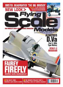
ON THE COVER
Richard Crapp’s Junkers D.1 makes a
low pass and last year’s Old Warden
Scale Weekend. Quarter-scale model
was bult from the Balsa USA kit,
supplied in UK by Pegasus Models..
Laser 300V Twin 30cc powered.
www.flyingscalemodels.com
THE ISSUE AHEAD...
6
20
40
JULY 2017 NO.212
4 CONTACT
Just for starters
6 BREGUET LE
Full size free plan feature
An electric powered model of an unusual French monoplane,
designed by Peter Rake
12 carve cockpit CANOPY PLUG
Chris White carves one the traditional qay - in wood
14 professor hugo’s TIN DONKEYS
Back in the WW1 period, Prof.Junkers’ all-metal airframe
fighters were nothing short of revolutionary in an era of wire,
wood and fabric for aircraft construction
20 junkers J.2
A 72” span model of this radical and futuristic 1916 fighter
monoplane for .50 to .60 cu. in. four-strokes designed
by GARY SUNDERLAND
26 J.2 SCALE DRAWING
1:40 scale three-views
28 Junkers D.1 MASTER MODEL
Richard Crapp’s quarter scale model, build from the
Balsa USA kit
34 D.1 SCALE DRAWING
1:40 scale three view drawing
36 JUNKERS D.1 TYPE HISTORY
Like the Fokker D.VII monoplane the Junkers D.1 arrived too
late during WW1, but its designer can truly be credited for the
advanced thinking that went into its design
40 INDOOR F/F SCALE NATIONALS
Tom Daly enjoys an action-packed day at this annual indoor scale jamboree
46 SUBJECT FOR SCALE
LAVOCHKIN LA-5 & LA-7
One of the Soviet Union's lesser-known fighters of WW2, this
handy little machine proved highly effective
52 LAVOCHKIN FLYING COLOURS
Warpaint schemes
56 LAVOCHKIN SCALE DRAWING
1:60 detialed finew-line three-views
58 BIPLANES MY WAY PART 6
Off to the flying field - at last...
62 QUIET ZONE
Peter Rake takes a look at up-to-date alternatives to the
motors originally recommended for some of the much earlier
model designs, still valid, but that would benefit from a modern
power system upgrade.
FORMATION JULY 17 Tony OK 25/5/17 15:30 Page 3
Editor: Tony Dowdeswell
Publisher: Alan Harman
Design: Peter Hutchinson
Website: Webteam
Advertising Manager: Sean Leslie
Admin Manager: Hannah McLaurie
Office Manager: Paula Gray
FLYING SCALE MODELS is published
monthly by Doolittle Media, Doolittle
Mill, Doolittle Lane, Totternhoe, Beds,
LU6 1QX. Reproduction in part or
whole of any text, photograph or
illustration without written permission
from the publisher is strictly prohibited.
While due care is taken to ensure the
contents of Flying Scale Models is
accurate, the publishers and printers
cannot accept liability for errors and
omissions. Advertisements are
accepted for publication in FLYING
SCALE MODELS only upon Doolittle
Media’s standard terms of
acceptance of advertising, copies of
which are available from the
advertising sales department of
FLYING SCALE MODELS.
EDITORIAL ADVERTISEMENT
& CIRCULATION: Doolittle Mill,
Doolittle Lane, Totternhoe, Beds,
LU6 1QX.
Tel. 01525 222573 Fax. 01525 222574.
Email:
[email protected]
CIRCULATION TRADE ENQUIRIES:
Seymour Distribution, 2 East Poultry
Avenue, London, EC1A 9PT
020 7429 4000.
NEWSTRADE: Select Publisher Services,
3 East Avenue, Bournemouth.
BH3 7BW.
01202 586848
Email:
[email protected]
SUBSCRIPTIONS: Doolittle Mill,
Doolittle Lane, Totternhoe, Beds,
LU6 1QX.
Tel. 01525 222573. Fax. 01525 222574.
PRINTING: Henry Stone Ltd.,
Oxfordshire
(c) Copyright Flying Scale Models
2017 Doolittle Media.
The paper used on this title is from
sustainable forestry
4 FLYINGSCALEMODELS JULY 2017
A
s I cleared the last
pages of July FSM for
press, the thought
occurred that two of
the main threads of this
issue represented a curious
crossover of construction
technologies.
Professor Hugo Junkers’ all-metal
monoplanes with cantilever wings
were the product of radical thinking
well ahead of the period during
which the concept was developed,
when aircraft, including Warbirds,
were wood and fabric creations
with wafer thin undercambered
aerofoil sections made rigid by
mares-nests of bracing wires. It was
a thread of aircraft construction that
dominated aviation for at least a
further decade and a half, before
military aircraft designers began to
embrace the performance
advantages of the monoplane
layout - but even then, as with types
like the Boeing P-26, still with the
‘safety’ of some degree of wire
wing bracing.
Transferring theory into practical
machinery risks its own setbacks
and Professor Hugo’s ‘Tin Donkeys’
had their own fair share of
difficulties along the way to military
service and arrived too late to have
any influence on the outcome of
WW1, but the concept was
successfully translated into viable
comercial peacetime types in the
post WW1 years - all metal
monoplanes free of external
bracing.
In contrast, in Russia a full world
war later, Semyon Lavochkin’s La-5
and La-7 fighters of WW2, also
featured in this issue, relied on
wood as the main airframe
construction material. Of course,
Science played its part in making
that possible, in creating the
bonding agents, as with that other
‘wooden wonder’, the De
Havilland Mosquito.
But in going against the grain of
progress (...sorry about that one!)
Lavochkin produced a series of
fighter aircraft that, at the low-to-
medium altitudes for which they
were designed, seriously out-
performed the likes of
Messerschmitt Me 109s and Focke
Wulf Fw 190s that were their main
adversaries on the WW2 European
eastern front. The Lavochkins were
not the only wooden pure fighter
aircraft of the WW2 period, but they
were far and away the most
successful.
Circumstances were different in
either case. Prof. Junker was a true
visionary, while Semyon Lavochkin
achieved the very best from the
hand dealt to him from a
specification that required the use
of non-stratigic materials.
CONTACT
BACK TO THE FUTURE ...
... and back again!
CONTACT JULY 17.QXT 25/5/17 11:22 Page 2
BELAIR MAR 17.indd 1 25/01/2017 12:23
BREGUET LE
FULL SIZE FREE PLAN FEATURE
An electric powered model of an unusual French monoplane, designed by Peter Rake, with the
prototype model built by Pat O'Donnell
B
ased on the history of the original
aircraft, the Breguet LE might not
seem the ideal choice for a flying
scale model, because the
prototype only made two flights
before being abandoned as an idea. The
first flight resulted in a crash that removed
the landing gear, while the second flight
(after repairs) ended in a crash that killed
the test pilot. So, not so much famous
as infamous!
However, fortunately for we modellers,
models do not always share the traits of
the prototype they are based on. If they
did, very few model Sopwith Camels
would get built and almost all modern jet
fighters would be impossible to even
consider. That’s the thing with models, they
can be designed to represent the full size
aircraft, but built so they have a more
than fair chance of actually doing what
they are supposed to do - fly in a
controlled manner. (Unless I’m the one
doing the stick stirring, in which case all
bets are off.)
You only have to look at the plan to see
that there’s nothing particularly unusual
about this model. Yes, it has quite a lot of
wing area and the nose is fairly short, but
that’s no different from so many other
models that give no problems at all. Why
the prototype should have been such a
failure is anyone’s guess because it all
looks straightforward enough to me. If it
had been really strange I would never
have agreed to draw the plans in the
first place.
THE MODEL
The little Breguet LE is a type I’d never
heard of until somebody contacted me to
ask about the possibility of a plan. He
supplied a three-view drawing and other
reference (what little there is) and a
promise to prototype the model once a
plan was prepared. Well, I’m sure you
know how it goes by now. The plan was
drawn and sent to the prospective builder,
who promptly disappeared. Oh well,
such is life.
Anyway, the design sat on my computer
for some time, until I thought it might be
something that would interest Pat. It was
and the model you see here is the result.
There’s nothing particularly difficult about
building this one but it is important that
you keep it light. If using a 300 size
outrunner (as shown on the plan) you’ll
need to keep the ready-to-fly weight
down to around 12 ounces. The e-Flite
Park 300 is good for about 50 Watts,
resulting in a power-to-weight rating of a
little over 60 Watts/lb. Pat’s model turned
out roughly 25% heavier than that so he
fitted a Turnigy motor capable of around
70 Watts to compensate for the higher
weight. However, it’s better if you can
keep the model light because that will
result in a lower wing loading and slower,
easier to control flight. Fast models may be
very thrilling, but their life expectancy
tends towards that of Lancaster tail
BREGUET FREE PLAN Tony OK.qxd 24/5/17 12:59 Page 2
gunners, not very long at all.
It’s also important to keep all the equipment as far forward
as you can possibly get it. The nose is, as I said, quite short, so
a few grams weight at the tail could easily require an ounce
of weight at the nose if the model is to balance correctly.
Avoid any hint of tail heaviness like the plague.
FUSELAGE
Let’s start with what is probably the most complicated part of
the model. At least, it’s the section involving the most work.
Apart from carving the nose blocks there isn’t really too much
that is complicated about it. It’s all pretty basic
modelling really.
The fuselage side frames are built in the traditional manner,
over the plan with the parts pinned to the board while the
glue dries. I know CA glue speeds up this process, but I would
recommend a PVA style glue for most of the basic building.
CA tends to result in brittle joints that don’t react well to any
flex they may encounter. PVA takes much longer to dry but
does result in a far more durable joint. I normally only use CA
where I need to tack something in position and have it ‘grab’
quickly to hold alignment. Even then I invariably reinforce the
joint with PVA. That, Titebond, Aliphatic, it doesn’t matter
which you use. All give more durable joints than CA and
they’re far less likely to run all over the place, sticking bits
where you don’t want bits stuck. That includes stuck to you.
Depending on how soft the wood used for the forward
fuselage sides is, you may need to put a few vertical saw cuts
on the inside face of each piece where they curve fairly
sharply inwards at the nose. You’ll have BT and F1 to clamp
them to but it’s much nicer if they curve easily and aren’t
constantly trying to spring straight as soon as the clamps
are removed.
Now you can start joining the fuselage sides into a basic box
structure. Glue parts WM to formers F2 and F4. Those holes that
don’t appear to do anything are actually intended to assist
with accurate alignment of the WM parts on the formers.
Since they are the parts that will ultimately determine equal
dihedral and correct incidence it’s vitally important that they
are in precisely the correct position on the formers. Take your
time to get that right and the final assembly should go
very smoothly.
Laminate F3 and F3A and assemble F1, BT and F2, ensuring
they all align precisely as shown on the plan. Whether you
bind the u/c tubes in place now, or once you have the basic
box structure complete is entirely down to you. Either way
works just fine.
Now, working over the plan and ensuring that everything
remains perfect straight and square, join the two sides using
the F1/BT/F2 assembly, F3/F3A and F4. Don’t worry about
pulling in the nose at the moment, that can be done once
the basic box structure is removed from the building board
and you have plenty of room to fit clamps and pieces of
scrap to prevent the clamps damaging the sides. Scrap
pieces of trailing edge stock work well for this because of
the taper.
To complete the basic box, and still working over the plan to
keep it all straight and square, pull in the tail and fit TS and all
the remaining formers. Cross braces for the lower longeron
should be cut to match their particular former width and are
from 1/8 square balsa. Allow to dry completely before
removing from the board and then pull in and glue in place
the front sides. Add the undercarriage tubes if you didn’t fit
them earlier. Add parts X, which provide the tailplane seat,
and the pushrod exit plates.
Sheet the top of the fuselage, around the cockpit, and glue
in place the stringers.
With the easy stuff done, let’s move onto the messy part -
fitting and shaping the nose blocks. As you’ll see from the
photos, Pat ‘cheated’ slightly here. Rather than use expensive,
and increasingly difficult-to-get, block balsa, he used bits and
pieces of sheet to make up the basics of these sections. Also,
rather than shape the blocks and then fit part N, temporarily
appied part N and fitted the pieces of balsa to suit the thrust
lines; neat, simple and pretty much impossible to get wrong.
Then it’s just a case of planing, sanding, filling and more
sanding until you have it shaped to your satisfaction.
Rocker covers and headrest can be made up now, but only
you know if you prefer to add them after covering, or cover
around them.
JULY 2017 FLYINGSCALEMODELS 7
CONSTRUCTION
As you can see, there’s nothing too involved with getting the
fuselage to this basic box stage. Just the remaining stringers and
nose blocks to go.
Landing gear legs plugged into their tubes and the axle soldered
in place. No way are those legs coming out of the tubes.
Pat’s temporary spacer used to
hold part N while he builds up
the balsa block sections
around it.
After shaping the nose looks
rather sleek, if a little hump
backed.
BREGUET FREE PLAN Tony OK.qxd 24/5/17 12:59 Page 3
The landing gear couldn’t get much simpler. Bend matching
pairs of undercarriage legs, plug them into their tubes in the
fuselage and solder the axle into place. Then just fair them
with scrap.
SPINNER
Now things get really messy. Tack glue a piece of blue foam to
S, having first fitted a mandrel (a bolt through the central hole)
and mount the whole thing in an electric drill. Spin it up and
carefully sand the foam to the required shape. As I said,
REALLY messy.
Please don’t try to use beaded foam, it won’t work; all you’ll
do is pull out beads during the sanding process and the holes
will fill with resin during the glassing stage, making balancing
the thing almost impossible. Blue foam and 1/2 ounce glass
cloth with thin coats of skinning resin evenly applied should
result in a perfectly balanced spinner with no further effort from
you. I’ve used the technique on much bigger spinners than this
without problems, like the one on a Morane Saulnier type N.
However, before glassing slice of your sanded foam, cover
the edges of S with polythene (to prevent the glass sticking to
it) and spot glue the foam back in place. Now apply your
glass cloth. Two, or at most three layers is ample. Spin
everything in the drill again and GENTLY sand the surface
smooth. The idea isn’t to sand into the glass, just to remove
anything that stands proud on the surface.
Remove S and trim your spinner to fit around your prop and
you’re just about there. Mount S to the prop driver first tighten
the prop and then lightly and carefully glue the spinner over
both. The lip formed around S during the glassing stage will
ensure accurate location of the spinner every time.
TAIL SURFACES
After what has already been built, the tail surfaces will come
as something of a rest cure. Apart from the dreaded
laminated rudder outline it’s just a case of simply building them
over the plan, allowing to dry and sanding.
Shape the wire joiner drill and groove the elevators to
accept the joiner and glue it in place. The only comment I
would make on this point is that it’s easier to match elevator
span to tailplane span if you make the elevator leading edge
all one piece, only separating them after you have the holes
drilled for the joiner.
WINGS
Apart from the fact that every rib in each panel is different
(the joys of tapered wings), building the wings is pretty
8 FLYINGSCALEMODELS JULY 2017
Although still awaiting those
remaining stringers and the
nose blocks, this is as close
as we get to the obligatory
naked model shot.
CONSTRUCTION
Pat’s replacement motor in place. Those wires will ultimately pass
through the hole you see just above the mount plate.
Typical of the tail surfac...