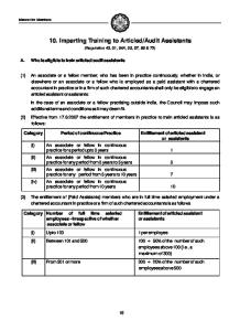
1 Wiring diagram CAN-series GB 14 71 88 41 5 UP 14111223 +- 25A P1P2P3P4 P5P6P7P8 P3.3 P3.1 P4.14 P4.7 P4.8 P4.9 P5 P6 P7 P8P1.6 P1.7 P1.8 P1.2 P1.3 P...
9 downloads
32 Views
377KB Size
"
5 0
O R A N G E /B R O W N , C A N L
O R A N G E /G R E E N , C A N H
W H IT E /B R O W N , L O C K N E G .
B L A C K
Y E L /B R O W N , U N L O C K N E G .
G R E E N
P 1 .6
P 1 .7
P 1 .8
P 1 .3
P 1 .2
P 1 .1 P 3 .4 P 3 .3
-
+
B L A C K /G R A Y , B O N N E T S W IT C H
7
1 4
P 4 .6
P 4 .7
G R A Y /R E D , L IG H T 1
1
P 4 .1 4
4
P 3
B L A C K , G R O U N D G R A Y /B L A C K , L IG H T 2
R E D , + 1 2 V
P 3 .1
5
P 3 .2
1
2 5 A
4
P 2
R E D /B L A C K , S T A R T E R K IL L IN
W H IT E /G R E E N , S T A R T E R K IL L O U T
R E D
P 1 .5
8
P 1 P 4
8
P 4 .4
1 4
1 2
P 6
1 3
P 7
R E G R B L B L
1
D , E E U E A C
P 8
2
P 6
P 7
P 8
+ 1 2 V N , S E N S O R T R IG G E R 1 , S E N S O R T R IG G E R 2 K , G R O U N D
1
W H IT E /R E D , A U X IL IA R Y E Q U IP M E N T
P 4 .8 P 4 .9
P 5
P 5
U P
GB
Wiring diagram CAN-series
1
GB
Content Wiring diagram Instructions for wiring diagram Preparation for installation Positioning of the various units of the alarm Emergency deactivation Programming new Remote Controls CAN-bus connection, connection of central locking and Programming Panel Programming the alarm Technical data
P. 4 P. 5-6 P. 7 P. 7-8 P. 8-9 P. 9 P. 10 P. 10-15 P. 15
Instructions for wiring diagram See technical manual for further information P- 1 CAN-bus connection, connection of central locking (DEFA remote control) and Programming Panel (Original remote control). See page 10. P-2 Multiplug, Backup Alarm/Siren, Immobilizer and Pager (auxiliary equipment). This is the connection for auxiliary equipment such as the DEFA Backup Alarm/Siren, the DEFA Immobilizer module and Pager (remote alarm) See separate assembly instructions. P-3.1 +12V supply, red wire. To be connected to a distribution centre (fuse box) via an 25A fuse. P-3.2 Not in use. P-3.3 Ground, black wire. Connect directly to the vehicle body. NOTE! Wire must not be extended. P-3.4 Not in use. P-4.1 Channel 3. Output for Remote Control of the DEFA WarmUp Heating System. When activated this output will deliver +12V until it is turned off. Maximum load: 350mA. P-4.2 Channel 2. When activated this output will be ground connected as long as the button is depressed. Usage is optional. Maximum load: 350mA. P-4.3 Channel 1. When activated the output will connect to ground for 1 second. This function is only available when the alarm is deactivated. Maximum load: 350mA. P-4.4 Auxiliary equipment, white/red wire. This alarm loop protects integrated auxiliary equipment in the car such as radio/cassette player or similar equipment. The circuit is normally closed (NC) and triggers the alarm when interrupted. 2
GB P-4.5 Not in use (ground out). P-4.6 Hood trigger, black/grey wire. This input is normally open (NO) and triggers the alarm when connected to ground, i.e. when the hood is opened. Install DEFA Hood Switch. It must be installed so that it can't be reached from underneath or the front of the car. P-4.7 Light output 1, grey/red wire. To be connected directly to the right turn signal circuit of the car. Maximum load: 7,5 Amp (90 watt). Fused with an automatic circuit breaker. P-4.8 Siren. Output to loudspeaker Siren. Connect the two siren wires to P4.8 and P4.9. P-4.9 Siren. Output to loudspeaker Siren. Connect the two siren wires to P4.8 and P4.9. P-4.10 Normally not in use (ignition signal, white/brown wire). (The wire is connected to the ignition outlet on the ignition switch). P-4.11 Not in use (ground out). P-4.12 Not in use. P-4.13 DEFA-net. This output controls the DEFA Power Module( if connected). P-4.14 Light output 2, grey/black wire. To be connected directly to the left turn signal circuit of the car. Maximum load: 7,5 Amp (90 watt). Fused with an automatic circuit breaker. P-5 Plug for auxiliary sensors. See separate assembly instructions. P-6 Plug for Glassbreak Sensor. Standard for all models with the letter G in the model designation. If a window is broken, the Glassbreak Sensor triggers the alarm. P-7 Plug for Microwave Sensor. P-8 Plug for LED. Universal diode bracket: The LED can be installed on the instrument panel, on the A-pillar, the windscreen or any other desired position. Embedded diode bracket: Use an 8.0 mm drill if the bracket is to be embedded in metal plates, a 7,5 - 8,0 mm drill for plastic material and a 7,0 mm drill for padding material.
Alarm ON (arm)
3
GB
Preparations for installation The workshop is always responsible for all necessary safety precautions when installing an alarm. Follow the car manufacturers instructions. Always check the connections with a voltmeter or multimeter before connecting. Always make sure the connections are properly insulated, use shrink hose or tape. Avoid positioning connections and units in immediate proximity of airbag modules or other safety systems.
Central Positioning of the various units of the alarm Central Unit: Attach the Central Unit below the instrument panel or a suitable point in the vehicle interior using plastic fastening strips. The Central Unit should not be visible and not easily accessible. NOTE! To avoid water (condensation) entering the central unit along the cables, it must be fitted with the plugs pointing downwards. Main fuse: The main fuse (25 amp.) should be attached in the vicinity of the current power source. Siren: Install in the engine compartment, exposed as little as possible to spray water and heat from exhaust or turbocharger components, minimum distance 30 cm. The siren aperture must face downwards in order to prevent water accumulating in it. The Siren must not be accessible from underneath the car. NOTE! Never install the Siren with the aperture facing upwards. Hood Switch: Install in the engine compartment exposed as little as possible to spray water and not accessible from underneath the car or after removing grill and lights. Install cables in such a way that they are as protected as possible and not easily accessible. Install the switch at a distance of 10-20 mm when the hood is closed. The hood may than be opened a few millimetres before the switch gives a signal. The switch signals between 25-35 mm fitted on a steel base and between 22-35 mm fitted on a plastic base. Position the switch with the arm pointing forwards or to one side and fasten it with the attached screws. The use of magnetic screwdriver bits may influence the switch and prevent it from functioning according to specification. The ground wire should not be attached to the fastening screw as it may cause the switch to get stuck. Use a separate ground screw. NB ! For alarm signal only. Do not connect directly to 12 or 24V. Glassbreak Sensor: The glass breakage sensor is fitted to the instrument panel or in the centre console. Clean the installation surface with a grease dissolving agent and then fasten the glass breakage sensor with double-sided adhesive tape.
4
GB LED: Install in instrument panel using the embedded bracket or fasten to the windscreen using a universal Bracket and a double-sided adhesive tape. The LED must be clearly visible from the outside. Microwave Sensor: The preferred location is at the centre of the car roof, 40 cm from the windscreen, under the roof lining.If this is not possible, it can be installed in the centre console. The sensor can be installed behind plastic covers but not behind metal covers, as these would block the waves for the sensor. Please note that some cars have a thin metal film in the roof lining. In these cases, the sensor must not be installed behind this lining. If the sensor is attached to the inside of the roof, the arrow with the mark UP is usually located on the underside of the sensor and points towards the rear of the car interior. If the sensor is attached to the centre console, the arrow with the mark UP is usually located on the side of the sensor facing the interior. The sensitivity of the sensor must be checked and, if necessary, adjusted after installation - see programming in the technical manual. NOTE! Loose metal objects such as keys, coins, etc., can trigger the alarm if they are too close to the sensor. Antenna cord (DEFA remote control): The active part of the antenna (white) must installed as highly and freely as possible and not in the vicinity of metal or other wires. How the antenna is installed will greatly affect its range. Programming Panel (Original remote control): The active part of the antenna (white) must installed as highly and freely as possible and not in the vicinity of metal or other wires. How the antenna is installed will greatly affect its range. Alarm decals (stickers): DEFA Auto Security (3 stickers) and FG identification (3 stickers) are attached to the front side windows; the last one can be attached either to the windscreen or the rear screen. NOTE! The decals must not obscure the driver's line of sight. The decal with details of the alarm model is attached to the lower part of the B-pillar, not visible from the outside. The relevant model is checked.
Emergency deactivation If the Remote Control is broken or lost, deactivate the alarm as follows: A. Locate your PIN-code card. There you will find your 5-digit PIN-code. B. Follow the procedure on the emergency code card. NOTE! If you make a mistake, you can repeat the procedure from 3 onwards as often as required. 5
GB
Your Emergency Code is:
DEFA CAN ALARM P/N:10011 D S/N: 1234567 PIN-kode: X- X- X- X- X
1. Unlock and open the car door. The Alarm is activated ! 2. Turn the ignition ON and OFF five times in a row. The Led "flickers".
GB
3. When you turn ON the ignition once again, the Led will flash. Let the Led flash as many times as the first digit of your PIN-kode, and turn OFF the ignition.
4. Turn ON the ignition and repeat the procedure until you have gone through every digit in your PIN-kode. The Alarm is now disarmed. If you make a mistake, start over again at step 3.
Start the car immediately !
Programming of new DEFA Remote Controls A. Disarm the alarm and eventual Immobilizer with the Remote Control. Emergency deactivation may also be used. B. Turn the ignition on and off 5 times in rapid succession. The LED flashes rapidly. C. When you turn the ignition on again the LED must flash. Let the LED flash the number of times indicated by the first digit in your PIN-code and turn the ignition off (the LED stops flashing). D. Turn the ignition on again and repeat the procedure until you have covered all the digits in the PIN-code. E. The LED flashes rapidly. If you make a mistake you can start from "C" with the first digit in the PIN-code. F. Turn the ignition on again and press button A and B simultaneously on the Remote Controls to be coded (one Remote Control at the time). Hold the buttons depressed until you have received confirmation through both light and sound. G. Turn off the ignition when all the remote controls are coded. NOTE! When keys are coded all old codes are erased. A maximum of 4 DEFA Remote Controls may be coded. The original Remote Control for the vehicle need not be coded to the DEFA Alarm, this happens automatically. 6
GB
Connection of CAN-bus, central locking and programming panel Attach to the instrument panel or in the glove compartment. Used only for programming of the alarm. P-1 multiplug for CAN-bus connection, central locking (DEFA remote control) and Programming Panel (Original remote control). The CAN-bus connection consists of two connecting wires, which are connected to the existing (original) CAN-bus. The digital bus transmits a lot of information concerning the conditions in the car to the alarm. This may for instance be locking/unlocking via Remote Control or via the key in the door, opening/locking of doors/boot lid, ignition on and off. Connecting to this bus therefore reduces the total number of connections to the car. After power up, the alarm automatically starts searching for the CAN-bus communication in the car. in this period the LED will flash rapidly. On most cars the central locking must be controlled by analogue signals. There are two negative outputs for this purpose. This is only necessary if you wish to control the central locking via DEFA Remote Control. The connection to these outlets also gives access to comfort functions on VW and Skoda. The programming panel is connected to the P-1 plug as shown in the wiring diagram on the cover. This concerns only the alarm when operated with a original remote control.
P-1 Plug
Function
Colour
P1.1
Programming panel
Green
P1.2
UNLOCK (ground)
Yellow/brown
P1.3
Programming panel
Black
P1.4
Not in use (+12V, out)
P1.5
Programming panel
Red
P1.6
CAN L
Orange/brown
P1.7
CAN H
Orange/green
P1.8
LOCK (ground)
White/brown
Programming the alarm The alarm contains a register that allows various functions to be programmed or altered using the Remote Control/Programming Panel and the ignition key. See detailed description of the functions on the following pages. Definition of long and short depresses of the buttons on the DEFA remote Control. A short press means that you press the button for less than 1 second. A long press means that you press the button for at least 2 seconds. 7
GB
Function:
Description:
1
Alarm history
2
Number of DEFA remote controls
3
Alarm sound
4
Vandalism protection of lock cylinders
5
See technical manual
6
DEFA Remote Control with slide switch
7
Central locking control
8
Confirmation flash
9
Immobilizer
10
Comfort locking/unlocking
11
Panic function (remote release of the alarm)
12
Factory settings
13
Entry of PIN-code for Immobilizer Programming procedure
A. Turn the ignition ON and OFF 5 times in rapid succession. The LED flashes rapidly. B. Turn the ignition ON again and let the LED flash twice before you turn the ignition OFF. Repeat this 5 times. The fifth time the LED will flash rapidly when the ignition is turned OFF. C. Turn the ignition ON. A short press on button A takes you to function 1. The current function will always be indicated by the number of sound signals. D. Another short press on button A takes you to the next function. A long press on button A takes you back to the previous function. E. When you arrive at the required function, it is programmed/changed as described on page 16, 17, 18 and 19. F. Press button A short if you wish to programme several functions. You can than select functions by short or long presses on button A. G. Turn the ignition OFF when the programming is completed
Function 1: Alarm history Press button B short for information on what last triggered the alarm. By pressing button B short again the next stored alarm is shown (second last triggered). A long press on button B returns to the previous alarm and so on.A long press simultaneously on button A and B erases the alarm history. The central unit can store up to 10 alarm releases. 8
GB Alarm triggered by: Number of flashes. Auxiliary sensor 1 2 Door opened 3 Hood opened 4 Boot lid opened 5 Ignition 6 Attempt to remove protected equipment (stereo, ski box, etc.) 7 Microwave Sensor 8 Glassbreak Sensor 9 Auxiliary sensor 2 10
Function 2: Number of DEFA Remote Controls A short press on button B indicates the number of Remote Controls connected to the alarm. The number of flashes corresponds to the number of Remote Controls.
Function 3: Alarm sound A short press on button B activates the current alarm sound for 5 seconds. Another short press on button B selects the next alarmsound and a long press selects the previous alarm sound. 6 different alarm sounds are available.
Function 4: Vandalism protection of the lock cylinders (VW and Skoda) The vandalism protection of loch cylinders means the alarm should be triggered when the comfort opening function (window down) from the lock cylinders is used. If the comfort function is used from the doors, the alarm will indicate alarm triggered on door (3 flashes). If the comfort function is used from tailgate/boot lid, the alarm will indicate alarm triggered on tailgate/boot lid (5 flashes).Short press on button B indicates: 1 flash if vandalism protection is not selected. 2 flashes if vandalism protection is selected (standard). Another short press on button B selects the next function. The number of confirmation signals indicates current status.
Function 5: See technical manual The function can only be used by workshops authorised by DEFA .
Function 6: Adjustment of DEFA Remote Control with slide switch The Remote Control with slide switch can be adjusted in 3 different ways: 9
Programming
Short A
Long A
Short B
Long B
1 flash
Alarm ON
Close window
Alarm OFF
Open window
2 flashes
Alarm ON
3 flashes (Standard)
Alarm ON
Sunroof slide close or Channel 2
Sunroof tilt close or Channel 3 (Start car heating)
Alarm OFF
Alarm OFF
Slide switch position
Sunroof slide open or Channel 1 Opening luggage compartment Sunroof tilt open or Channel 3 (Turn off car heating)
Programming 1 gives you the functions on line 1 in the table. GB Programming 2 gives you the functions on line 1 and 2 in the table. Programming 3 gives you the functions on line 1, 2 and 3 in the table. If programming 1 is selected the middle and the upper slide switch position may be used to control the alarm on 2 other cars. If programming 2 is selected the upper slide switch position may be used to control the alarm on 1 other car. If you only want to control electrical windows, it can be done with the original Remote Control (1:1) of the alarm. A Remote Control with slide switch is not needed. A condition for the programming is that the Remote Control is coded with slide switch in the lower position. Short press on button B indicates the programming of the slide switch: 1 signal indicates programming 1, 2 signals 2 and 3 signals programming 3. Renewed short press on B selects the next programming, long press on B selects the previous programming. The number of confirmation signals indicates the selected programming.
Programming 1 gives you the functions on line 1 in the table. 10
GB
Function 7: Central locking control Short press on B indicates current central locking control. 1 flash = 0,5 seconds negative pulse (recommended for VW and Skoda), (standard) 2 flashes = CAN-bus control of the central locking (automatic selection for Mercedes) The function is set automatically when the alarm central has concluded that it is installed in a Mercedes. The search starts every time the alarm is connected to operating voltage. Another short press on button B selects the next central locking control and a long press selects the previous central locking control. The number of confirmation signals indicates the selected central locking control.
Function 8: Confirmation flash Short press on B indicates current setting. When the function is active the alarmgives confirming flashes when arming/disarming.1 flash = confirmation flash OFF (automatic selection for Mercedes, can not be changed),(standard). 2 flashes = confirmation flash ON (recommended for cars with no original central locking, such as certain VW and Skoda). The function is set automatically when the alarm centre has concluded that it is installed in a Mercedes. The search starts every time the alarm is connected to operating voltage. Another short press on button B selects the next function. The number of confirmation signals indicates current status.
Function 9: Immobilizer Short press on button B indicates current setting. The Immobilizer function is activated 30 seconds after the ignition is turned off. 1 flash = Immobilizer function selected. 2 flashes = Immobilizer function not selected (standard). Another short press on button B selects the next function. The number of confirmation signals indicates current status.
Function 10: Comfort locking/unlocking, DEFA remote control It is possible to close windows (and sunroof) at the same time as you turn the alarm on with the DEFA Remote Control.Short press on B indicates current setting. 1 flash = the function is not selected. 2 flashes = comfort closing/opening via the original system (standard). 3 flashes = comfort closing/opening via DEFA Power Module (only closes electrical windows). Renewed short press on B selects the next type of comfort closing/opening, long press on B selects the previous type of comfort closing/opening. The number of confirmation signals indicates the selected type of comfort closing/opening.To use the function: long press on A until everything is closed or long press on B to open. 11
GB
Function 11: Panic function, DEFA remote control Short press on B indicates current setting. 1 flash = the function is not selected. 2 flashes = the panic function is active as long as the buttons A and B are depressed (standard) 3 flashes = the panic function is active for 30 seconds after the buttons A and B have been pressed ( the buttons may be released). Another short press on button B selects the next function. The number of confirmation signals indicates current status.
Function 12: Factory settings The functions are set as follows at the factory: Function 3: Alarm sound: 1. Function 4: Vandalism protection of lock cylinders: ON. Function 6: Full functions 3:1 key programming (programming 3). Function 7: Central locking control: 0,5 seconds negative pulse. Function 8: Confirmation flash: OFF. Function 9: Immobilizer not selected.
Function 13: Entry of PIN-code for Immobilizer If an Immobilizer/Central Unit is retrofitted or replaced the PIN-code of the Immobilizer must be entered into the alarm to allow the vehicle to be started. 1. Short press on button B. 2. Turn the ignition OFF. 3. Turn the ignition ON, let the LED flash the number of times indicated by the first digit in the Immobilizer PIN-code. 4. Turn the ignition OFF. 5. Repeat 3 and 4 until all the digits in the PIN-code have been entered. The last time you turn the ignition off the LED will flash rapidly. This means the coding is completed. 6. If you make a mistake, you will have to start the procedure again.
Technical data Central unit, DEFA CAN ALARM Operating voltage: 9-15 Volt DC Operating temperature: -40°C to +85°C External measurements: 159 * 80 * 34 mm Power consumption: Armed DEFA CAN-G: 13 mA 16 mA DEFA CAN-M: 19 mA 16 mA DEFA CAN-MG: 19 mA 16 mA DEFA CAN-MG BA/BS : 29 mA 33 mA
Disarmed
12


![Superbase 06 - Cherry Point. Can Do and Harrier II [Osprey Superbase 06]](https://docer.tips/img/300x300/superbase-06-cherry-point-can-do-and-harrier-ii-os_5a5695c3d64ab26118c5d934.jpg)